US5328076A - Stabilized clincher for stitcher - Google Patents
Stabilized clincher for stitcher Download PDFInfo
- Publication number
- US5328076A US5328076A US08/130,806 US13080693A US5328076A US 5328076 A US5328076 A US 5328076A US 13080693 A US13080693 A US 13080693A US 5328076 A US5328076 A US 5328076A
- Authority
- US
- United States
- Prior art keywords
- clincher
- secured
- mounting bar
- bar
- side plates
- Prior art date
- Legal status (The legal status is an assumption and is not a legal conclusion. Google has not performed a legal analysis and makes no representation as to the accuracy of the status listed.)
- Expired - Lifetime
Links
Images


Classifications
-
- B—PERFORMING OPERATIONS; TRANSPORTING
- B27—WORKING OR PRESERVING WOOD OR SIMILAR MATERIAL; NAILING OR STAPLING MACHINES IN GENERAL
- B27F—DOVETAILED WORK; TENONS; SLOTTING MACHINES FOR WOOD OR SIMILAR MATERIAL; NAILING OR STAPLING MACHINES
- B27F7/00—Nailing or stapling; Nailed or stapled work
- B27F7/17—Stapling machines
- B27F7/19—Stapling machines with provision for bending the ends of the staples on to the work
Definitions
- the instant invention relates to stitching (stapling) apparatus used in document feeding systems, and more particularly to apparatus for stabilizing the clincher in a stitching device.
- the stitch is in the form of a rectangle that is almost closed on the bottom, i.e., the two legs are bent (clinched) somewhere between their ends so that they face each other and have sections substantially parallel to the top side.
- the height of the stitch is the difference between the top side and the bent sections of the two legs.
- the instant invention provides apparatus in a stitcher which maintains uniform compression of the clinched portion of the stitch and assures uniform height of the stitch.
- the instant invention provides apparatus for stapling documents.
- the apparatus comprises: a pair of side plates; a stitch head mounting bar secured to the side plates; a clincher mounting bar secured to the side plates; a stitch head mounted on the stitch head mounting bar; a clincher mounted on the clincher mounting bar; a pair of fixture plates secured to the side plates; a clincher actuating bar slidingly engaging the pair of fixture plates; a shaft seated in the fixture plates; a clincher actuating arm rotatably mounted on the shaft and engaging the clincher actuating bar; and means for rotating the clincher actuating arm whereby the clincher is moved up into clinching position and down away from the clinching position.
- FIG. 1 is a perspective view of a stitching apparatus in accordance with the instant invention
- FIG. 2 is an exploded view of the apparatus seen in FIG. 1;
- FIG. 3 is a perspective view of the drive linkage for the clincher
- FIG. 4 is an exploded view of the apparatus seen in FIG. 3;
- FIG. 5 is a sectional view taken on the plane indicated by the line 5--5 in FIG. 7;
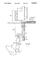
- FIG. 6 is a vertical, sectional view of the apparatus seen in FIG. 1 prior to stitching.
- FIG. 7 is similar to FIG. 6 but shows the apparatus immediately after clinching.
- a stitcher generally designated 10 which is employed in many document feeding systems to staple together a collation of documents 11.
- the stitcher 10 includes a pair of side plates 12 on which are fixedly mounted a stitch head mounting bar 14 and a clincher mounting bar 16.
- the stitch head mounting bar 14 supports the two stitch heads 18 and the clincher mounting bar 16 supports the two clinchers 20.
- the stitch head 18 feeds a section of wire 22 through the documents 11 to be stapled (stitched) toward the clincher 20 which bends the ends of the wire 22 to form a staple in a conventional process which is well known.
- both the stitch head mounting bar 14 and the clincher mounting bar 16 are secured to the side plates 12.
- a pair of fixturing plates 24 is secured to a side plate 12 and secure the stitch head mounting bar 14 to the clincher mounting bar 16 at the ends thereof.
- Each fixturing plate 24 is secured to a side plate 12 and includes a vertical, upper section 26 which is secured by screws 28 to the stitch head mounting bar 14, an angled, intermediate section 30 and a lower, vertical section 32 which is secured by screws 34 to the clincher mounting bar 16.
- Each clincher 20 is mounted on a bracket 51 which is secured to the clincher mounting bar 16.
- the bottom of each clincher 20 includes a slot 53 which engages a vertically extending flange 55 of a clincher actuating bar 57 (see FIG. 2).
- the fixture plates 24 each include a channel 59 for slidingly engaging the clincher actuating bar 57.
- the clincher actuating bar 57 includes a pair of apertures 61 which engage the ends of a pair of clincher actuating arms 63.
- Each of the actuating arms 63 is fixedly mounted on a shaft 65 which is seated at its ends in the fixturing plates 24.
- Each clincher 20 must be moved up from the position seen in FIG. 6 to the position seen in FIG. 7.
- the clincher actuating bar 57 is moved upward by the clincher actuating arm 63 which is moved upward by a bracket 66 which is rotated by a cam follower 67.
- the bracket 66 is secured to the cam follower 67 and the bracket 66 rotates about the shaft 65.
- the actuating arm 63 is fixedly secured to the bracket 66.
- the cam follower 67 rides on a cam 69 mounted on a cam shaft 71.
- rotation of the cam shaft 71 causes the actuating arm 63 to rotate which moves the actuating bar 57 up and down.
- the actuating bar 57 Prior to stapling, the actuating bar 57 is down and thus the clinchers 20 are down, as seen in FIG. 6. When stitching is required, the actuating bar 57 is moved up and thus the clinchers 20 are moved up into the positions seen in FIG. 7. In effect, the clinchers 20 are functioning as anvils for the wire sections 22.
Abstract
Apparatus for stapling documents. The apparatus includes: a pair of side plates; a stitch head mounting bar secured to the side plates; a clincher mounting bar secured to the side plates; a stitch head mounted on the stitch head mounting bar; a clincher mounted on the clincher mounting bar; a pair of fixture plates secured to the side plates; a clincher actuating bar slidingly engaging the pair of fixture plates; a shaft seated in the fixture plates; a clincher actuating arm rotatably mounted on the shaft and engaging the clincher actuating bar; and a device for rotating the clincher actuating arm whereby the clincher is moved up into clinching position and down away from the clinching position.
Description
The instant invention relates to stitching (stapling) apparatus used in document feeding systems, and more particularly to apparatus for stabilizing the clincher in a stitching device.
There are many applications today in which documents are fed along a feed path and then collated for further processing. In many cases the documents must be properly aligned prior to insertion into an envelope. In a significant number of applications, it is necessary that the documents be secured to one another, i.e. stitched or stapled together. There is a universal stitcher that is well known in the art and it is available for a variety of applications in which stapling of documents is required. The stitch is in the form of an open rectangle prior to clinching, i.e., it consists of a top side and two vertical legs extending downwardly from the top side. After clinching, the stitch is in the form of a rectangle that is almost closed on the bottom, i.e., the two legs are bent (clinched) somewhere between their ends so that they face each other and have sections substantially parallel to the top side. The height of the stitch is the difference between the top side and the bent sections of the two legs.
In prior art stitchers, the height of the stitch for a particular collation has varied considerably, resulting in non-uniform stitching which contributes to alignment problems with the documents, and complicates processing downstream of the stitching.
Accordingly, the instant invention provides apparatus in a stitcher which maintains uniform compression of the clinched portion of the stitch and assures uniform height of the stitch.
Accordingly, the instant invention provides apparatus for stapling documents. The apparatus comprises: a pair of side plates; a stitch head mounting bar secured to the side plates; a clincher mounting bar secured to the side plates; a stitch head mounted on the stitch head mounting bar; a clincher mounted on the clincher mounting bar; a pair of fixture plates secured to the side plates; a clincher actuating bar slidingly engaging the pair of fixture plates; a shaft seated in the fixture plates; a clincher actuating arm rotatably mounted on the shaft and engaging the clincher actuating bar; and means for rotating the clincher actuating arm whereby the clincher is moved up into clinching position and down away from the clinching position.
FIG. 1 is a perspective view of a stitching apparatus in accordance with the instant invention;
FIG. 2 is an exploded view of the apparatus seen in FIG. 1;
FIG. 3 is a perspective view of the drive linkage for the clincher;
FIG. 4 is an exploded view of the apparatus seen in FIG. 3;
FIG. 5 is a sectional view taken on the plane indicated by the line 5--5 in FIG. 7;
FIG. 6, is a vertical, sectional view of the apparatus seen in FIG. 1 prior to stitching; and
FIG. 7 is similar to FIG. 6 but shows the apparatus immediately after clinching.
In describing the preferred embodiment of the instant invention, reference is made to the drawings, wherein there is seen a stitcher generally designated 10 which is employed in many document feeding systems to staple together a collation of documents 11. The stitcher 10 includes a pair of side plates 12 on which are fixedly mounted a stitch head mounting bar 14 and a clincher mounting bar 16. The stitch head mounting bar 14 supports the two stitch heads 18 and the clincher mounting bar 16 supports the two clinchers 20. The stitch head 18 feeds a section of wire 22 through the documents 11 to be stapled (stitched) toward the clincher 20 which bends the ends of the wire 22 to form a staple in a conventional process which is well known.
As seen above, both the stitch head mounting bar 14 and the clincher mounting bar 16 are secured to the side plates 12. A pair of fixturing plates 24 is secured to a side plate 12 and secure the stitch head mounting bar 14 to the clincher mounting bar 16 at the ends thereof. Each fixturing plate 24 is secured to a side plate 12 and includes a vertical, upper section 26 which is secured by screws 28 to the stitch head mounting bar 14, an angled, intermediate section 30 and a lower, vertical section 32 which is secured by screws 34 to the clincher mounting bar 16.
Each clincher 20 is mounted on a bracket 51 which is secured to the clincher mounting bar 16. The bottom of each clincher 20 includes a slot 53 which engages a vertically extending flange 55 of a clincher actuating bar 57 (see FIG. 2). The fixture plates 24 each include a channel 59 for slidingly engaging the clincher actuating bar 57. As best seen in FIG. 3, the clincher actuating bar 57 includes a pair of apertures 61 which engage the ends of a pair of clincher actuating arms 63. Each of the actuating arms 63 is fixedly mounted on a shaft 65 which is seated at its ends in the fixturing plates 24.
Each clincher 20 must be moved up from the position seen in FIG. 6 to the position seen in FIG. 7. The clincher actuating bar 57 is moved upward by the clincher actuating arm 63 which is moved upward by a bracket 66 which is rotated by a cam follower 67. The bracket 66 is secured to the cam follower 67 and the bracket 66 rotates about the shaft 65. The actuating arm 63 is fixedly secured to the bracket 66. The cam follower 67 rides on a cam 69 mounted on a cam shaft 71. Thus, rotation of the cam shaft 71 causes the actuating arm 63 to rotate which moves the actuating bar 57 up and down. Prior to stapling, the actuating bar 57 is down and thus the clinchers 20 are down, as seen in FIG. 6. When stitching is required, the actuating bar 57 is moved up and thus the clinchers 20 are moved up into the positions seen in FIG. 7. In effect, the clinchers 20 are functioning as anvils for the wire sections 22.
It should be understood by those skilled in the art that various modifications may be made in the present invention without departing from the spirit and scope thereof, as described in the specification and defined in the appended claims.
Claims (5)
1. Apparatus for stapling documents, comprising:
a pair of side plates;
a stitch head mounting bar secured to said side plates;
a clincher mounting bar secured to said side plates;
a stitch head mounted on said stitch head mounting bar;
a clincher mounted on said clincher mounting bar;
a pair of fixture plates secured to said side plates;
a clincher actuating bar slidingly engaging said pair of fixture plates;
a shaft seated in the fixture plates;
a clincher actuating arm rotatably mounted on said shaft and engaging said clincher actuating bar; and
means for rotating said clincher actuating arm whereby said clincher is moved up into clinching position and down away from said clinching position.
2. The apparatus of claim 1, wherein said rotating means comprises a bracket secured at one end to said shaft and a cam follower secured to the other end of said bracket.
3. The apparatus of claim 2, additionally comprising a cam engaging said cam follower and wherein rotation of said cam causes said clincher to move up into clinching position and down away from said clinching position.
4. The apparatus of claim 3, wherein said clincher includes a slot and said clincher actuating bar includes a vertically extending flange for engaging said slot.
5. The apparatus of claim 4, wherein said clincher actuating bar includes an aperture for engaging the end of said clincher actuating arm.
Priority Applications (1)
| Application Number | Priority Date | Filing Date | Title |
|---|---|---|---|
| US08/130,806 US5328076A (en) | 1993-10-04 | 1993-10-04 | Stabilized clincher for stitcher |
Applications Claiming Priority (1)
| Application Number | Priority Date | Filing Date | Title |
|---|---|---|---|
| US08/130,806 US5328076A (en) | 1993-10-04 | 1993-10-04 | Stabilized clincher for stitcher |
Publications (1)
| Publication Number | Publication Date |
|---|---|
| US5328076A true US5328076A (en) | 1994-07-12 |
Family
ID=22446423
Family Applications (1)
| Application Number | Title | Priority Date | Filing Date |
|---|---|---|---|
| US08/130,806 Expired - Lifetime US5328076A (en) | 1993-10-04 | 1993-10-04 | Stabilized clincher for stitcher |
Country Status (1)
| Country | Link |
|---|---|
| US (1) | US5328076A (en) |
Citations (6)
| Publication number | Priority date | Publication date | Assignee | Title |
|---|---|---|---|---|
| US694031A (en) * | 1901-03-29 | 1902-02-25 | John L Flannery | Box-stapling machine. |
| US892827A (en) * | 1906-10-08 | 1908-07-07 | John Graves | Fly-net machine. |
| US1007258A (en) * | 1909-05-03 | 1911-10-31 | Gaines M Walker | Staple forming and clenching machine. |
| US2019990A (en) * | 1932-07-29 | 1935-11-05 | Walter F Newhouse | Machine for making crate sides |
| US2513276A (en) * | 1949-08-03 | 1950-07-04 | Christensen Machine Co | Book-stitching machine |
| US3613217A (en) * | 1970-01-09 | 1971-10-19 | Harris Intertype Corp | Stitcher assembly |
-
1993
- 1993-10-04 US US08/130,806 patent/US5328076A/en not_active Expired - Lifetime
Patent Citations (6)
| Publication number | Priority date | Publication date | Assignee | Title |
|---|---|---|---|---|
| US694031A (en) * | 1901-03-29 | 1902-02-25 | John L Flannery | Box-stapling machine. |
| US892827A (en) * | 1906-10-08 | 1908-07-07 | John Graves | Fly-net machine. |
| US1007258A (en) * | 1909-05-03 | 1911-10-31 | Gaines M Walker | Staple forming and clenching machine. |
| US2019990A (en) * | 1932-07-29 | 1935-11-05 | Walter F Newhouse | Machine for making crate sides |
| US2513276A (en) * | 1949-08-03 | 1950-07-04 | Christensen Machine Co | Book-stitching machine |
| US3613217A (en) * | 1970-01-09 | 1971-10-19 | Harris Intertype Corp | Stitcher assembly |
Similar Documents
| Publication | Publication Date | Title |
|---|---|---|
| EP1736282B1 (en) | Stapler | |
| US6250531B1 (en) | Staple leg cutting mechanism for an electric stapler | |
| US4546910A (en) | Active clinchers and wire stitchers incorporating same | |
| US20010050302A1 (en) | Motor operated stapler | |
| US6871768B2 (en) | Stapler for forming staples to various sizes | |
| EP0904904A2 (en) | Staple clinching mechanism in stapler | |
| EP0200485A2 (en) | Bypass clincher for stitching machine | |
| US7913378B2 (en) | Wire stitcher having a stitching head for processing annular-eyelet staples | |
| US6257477B1 (en) | Stapler with internal guidance of the legs of a staple | |
| US5328076A (en) | Stabilized clincher for stitcher | |
| US4505415A (en) | Wire loop stitching machine head | |
| DE60314982T2 (en) | BOOK DEVICE | |
| US6616029B1 (en) | Stapler with reversible electric motor | |
| EP0013163B1 (en) | Active clinchers and wire stitchers incorporating same | |
| US4722467A (en) | Wire guide apparatus for wire stitching machine head | |
| US4537342A (en) | Binding machine for a signature machine | |
| US5280925A (en) | Fixturing plate for stitcher | |
| CA2108807A1 (en) | Power stapler | |
| JP2011056712A (en) | Electric stapler | |
| US6641024B2 (en) | Stapling device | |
| US20060213951A1 (en) | Locking mechanism for stapler paper presser table | |
| US6739492B1 (en) | Stapler for forming staples to various sizes | |
| US263390A (en) | Island | |
| EP1016502B1 (en) | Stapling device | |
| JP5050991B2 (en) | Stapler |
Legal Events
| Date | Code | Title | Description |
|---|---|---|---|
| AS | Assignment |
Owner name: PITNEY BOWES INC., CONNECTICUT Free format text: ASSIGNMENT OF ASSIGNORS INTEREST;ASSIGNOR:LOWELL, KENNETH W.;REEL/FRAME:006729/0406 Effective date: 19930923 |
|
| STCF | Information on status: patent grant |
Free format text: PATENTED CASE |
|
| FPAY | Fee payment |
Year of fee payment: 4 |
|
| FEPP | Fee payment procedure |
Free format text: PAYOR NUMBER ASSIGNED (ORIGINAL EVENT CODE: ASPN); ENTITY STATUS OF PATENT OWNER: LARGE ENTITY |
|
| FPAY | Fee payment |
Year of fee payment: 8 |
|
| FPAY | Fee payment |
Year of fee payment: 12 |