US5327416A - Surface selection mechanism for optical storage system - Google Patents
Surface selection mechanism for optical storage system Download PDFInfo
- Publication number
- US5327416A US5327416A US08/020,512 US2051293A US5327416A US 5327416 A US5327416 A US 5327416A US 2051293 A US2051293 A US 2051293A US 5327416 A US5327416 A US 5327416A
- Authority
- US
- United States
- Prior art keywords
- mirrors
- recording surface
- path
- light beam
- light
- Prior art date
- Legal status (The legal status is an assumption and is not a legal conclusion. Google has not performed a legal analysis and makes no representation as to the accuracy of the status listed.)
- Expired - Lifetime
Links
Images


Classifications
-
- G—PHYSICS
- G11—INFORMATION STORAGE
- G11B—INFORMATION STORAGE BASED ON RELATIVE MOVEMENT BETWEEN RECORD CARRIER AND TRANSDUCER
- G11B11/00—Recording on or reproducing from the same record carrier wherein for these two operations the methods are covered by different main groups of groups G11B3/00 - G11B7/00 or by different subgroups of group G11B9/00; Record carriers therefor
- G11B11/10—Recording on or reproducing from the same record carrier wherein for these two operations the methods are covered by different main groups of groups G11B3/00 - G11B7/00 or by different subgroups of group G11B9/00; Record carriers therefor using recording by magnetic means or other means for magnetisation or demagnetisation of a record carrier, e.g. light induced spin magnetisation; Demagnetisation by thermal or stress means in the presence or not of an orienting magnetic field
- G11B11/105—Recording on or reproducing from the same record carrier wherein for these two operations the methods are covered by different main groups of groups G11B3/00 - G11B7/00 or by different subgroups of group G11B9/00; Record carriers therefor using recording by magnetic means or other means for magnetisation or demagnetisation of a record carrier, e.g. light induced spin magnetisation; Demagnetisation by thermal or stress means in the presence or not of an orienting magnetic field using a beam of light or a magnetic field for recording by change of magnetisation and a beam of light for reproducing, i.e. magneto-optical, e.g. light-induced thermomagnetic recording, spin magnetisation recording, Kerr or Faraday effect reproducing
- G11B11/1055—Disposition or mounting of transducers relative to record carriers
-
- G—PHYSICS
- G11—INFORMATION STORAGE
- G11B—INFORMATION STORAGE BASED ON RELATIVE MOVEMENT BETWEEN RECORD CARRIER AND TRANSDUCER
- G11B7/00—Recording or reproducing by optical means, e.g. recording using a thermal beam of optical radiation by modifying optical properties or the physical structure, reproducing using an optical beam at lower power by sensing optical properties; Record carriers therefor
- G11B7/08—Disposition or mounting of heads or light sources relatively to record carriers
- G11B7/085—Disposition or mounting of heads or light sources relatively to record carriers with provision for moving the light beam into, or out of, its operative position or across tracks, otherwise than during the transducing operation, e.g. for adjustment or preliminary positioning or track change or selection
- G11B7/0857—Arrangements for mechanically moving the whole head
- G11B7/08594—Arrangements for mechanically moving the whole head to access both sides of the disc with the same head assembly
Definitions
- This invention relates generally to optical storage systems, and more particularly to a surface selection mechanism for optical storage systems.
- optical disc storage systems typically use a single optical sub-assembly, including a light source and a light detector, to read or write the information on an optical disc, such as for example, a compact disc (CD). Therefore, most CDs only have information recorded on a single side. The "flip" side of the CD is generally not used.
- the CD In order to access both sides of a double-sided CD, the CD must be flipped over by the user.
- the problem with such systems is that only one side of recorded information is accessible at any one time, and also the CD is more likely to be damaged due to excessive handling.
- FIG. 1 shows the problems associated with delivering a light beam from a single optical subassembly to both sides of an optical disc.
- an optical storage system of the type that can advantageously use the invention.
- the optical subassembly 5 generates a single light beam along the path indicated by reference numeral 1.
- the problem is to selectively direct this light beam along paths 1' and 1" to a first and second recording surface 11 and 12 of the disc 10 snap mounted onto the end of a spindle 21.
- the spindle 21 and the disc 10 are rotated by a motor 22.
- the system further includes a first and a second directing mirror 41, and 42 for directing the light beam parallel to the plane of the disc 10, along either path 1' or path 1".
- a first and second reflecting mirror 51 and 52 are attached to the end of actuator arms 61 and 62.
- the arms 61 and 62 radially position the reflecting mirrors 51 and 52 relative to the recording surfaces 11-12 of the disc 10.
- the reflecting mirrors 51 and 52 reflect the light beams from path 1' or path 1", perpendicularly to the recording surfaces 11 and 12, respectively.
- the light beam is modified and reflected back along its incident path to the optical subassembly 5, where the modified and reflected light beam is decoded and processed.
- magneto-optical disc technology the well known Hall effect is used to modify the light beam at the recording surface.
- Read-only discs use variations in the surface topology of the recording surface to modify the light beam.
- the mechanism disclosed is also applicable to other optical disc technologies, fixed or removable, single or multi-disk, and including write once, read only, and audio and video CD.
- galvo-galvanic mirrors at point X.
- galvo-mirrors are well known in the art. However, galvo-mirrors are relatively expensive and require complex servo control systems to accurately rotate the mirror to the desired angles. Also galvo mirrors may require longer settling times after positioning which induced latency into the system.
- the mechanism comprises a linearly movable slider having a first and second mirror mounted thereon.
- the first and second mirrors have reflective mirrors positioned at right angles with respect to each other.
- Means are provided for linearly positioning the slider so that either the first or second mirror is positioned at the optical axis of a light beam to direct the light beam at either a first or second recording surface of an optical disc.
- the advantages of the invention are due to a higher accuracy in the settling location of a linearly activated slider. As long as the light beam is beyond the border of the reflective surface, even should the mirror still be moving relative to the light beam, the light beam will be properly directed. In addition, the slidable mounted mirrors are more cost effective to implement than prior art surface selection devices.
- FIG. 1 is a schematic view of an optical storage system which can use the present invention
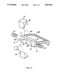
- FIG. 2 is a perspective view of a surface selection mechanism, according to the preferred embodiment of the invention, in a first position
- FIG. 3 is a perspective view of the surface selection mechanism in a second position
- FIG. 4 is a top plan view of a surface section mechanism according to an alternative embodiment.
- FIGS. 5 and 6 are perspective views of yet another alternative embodiment.
- FIGS. 2 and 3 show a preferred embodiment of the invention of a surface selection mechanism 100 for an optical storage system. It is intended that the mechanism 100 be placed at point X of FIG. 1 to selectively direct the light beam from path 1 to either path 1' or path 1".
- the surface selection mechanism 100 comprises a slider 110 having a mounting surface 114, and a first and second end portion 111 and 112.
- the mounting surface 114 faces in the direction of the incident light beam along path 1 as shown in FIG. 1.
- the slider 110 preferably includes a ferromagnetic material, or alternatively is made as a permanent magnet.
- the end portion 111 and 112 are fixed to a flexure 120 having flexure arms 123 and 124.
- the flexure 120 is generally U-shaped, with the end of the arms 123-124 attached to the end portions 111 and 112 of the slider 110, respectively.
- the flexure 120 is preferably made of a spring-like material, such as steel. The flexure is arranged to constrain the motion of the slider 110 in a linear direction with respect to the light beam.
- a first and second stationary winding 121 and 122 are located adjacent to each end portion 111 and 112 of the slider 110.
- the axis of the windings 121 122 are parallel to, and in-line with the linear axis of the slider 110.
- the slider 110 is reciprocated in a linear direction in response to a magnetic field generated by the windings 121 and 122.
- a first and second selecting mirror 101 and 102 are mounted on the mounting surface 114 of the slider 110.
- the selecting mirrors 101 and 102 are disposed side by side with the reflecting surfaces of the selecting mirrors 101 and 102 at fight angles with respect to each other. That is, each selecting mirror 101 and 102 is at an angle of 45° with respect of the optical axis of the light beam.
- the selecting mirrors 101 and 102 can also be 45° folding prisms.
- the disc 10 is rotated at a high speed.
- the arms 61 and 62 position the reflecting mirrors 51 and 52 adjacent to the recording surfaces 11 and 12.
- the optical subassembly 5 generates a light beam which is directed at the double-sided disc 10 along path 1 generally in the same plane as disc 10.
- the windings 121 and 122 are energized, to linearly reciprocate the slider 110 along an axis which is at fight angles with respect to the axis of the light beam along path 1.
- the first selecting mirror 101 is placed at point X, as is shown in FIG. 2.
- the second selecting mirror 102 is placed at point X to direct the light beam along path 1".
- the linear motion of the slider 110 allows the light beam to be directed in directions differing by an angle of 180° depending whether the first or second selecting mirrors 101-102 are positioned at point X.
- FIG. 4 An alternative embodiment of the surface selection mechanism is shown in FIG. 4 in plan view.
- iron cores 151 and 152 are inserted in the first and second windings 121 and 122, respectively, to increase the strength of the magnetic field to move the slider 110.
- FIGS. 5 and 6 shows yet another alternative embodiment.
- the slider 110 is mounted on a slide 140.
- the slider 110 includes a groove 113 to engage with a complementary tongue 141 formed on the mating side of the slide 140.
- the length of the slide 140 is made longer than the length of the slider 110 so that the slider 110 can linearly move end to end on the slide 140 to selectively position the selecting mirrors 101 and 102 at point X.
- the first end portion 111 of the slider 110 is attached to a spring 160.
- a winding 170, (with or without an iron core) is placed at the second end portion 112 of the slider 110.
- the energized winding 170 is used to pull the slider 110 to the position shown in FIG. 5.
- the spring 160 is used to pull the slider 110 to the position shown in FIG. 6 when the winding 170 is not energized.
- the invention has the advantage that the linear translation of the mirror pair 101 and 102 does not require accuracy as to its settling location. That is, as long as some portion of the selected mirror 101 or 102 is at point X the light beam will be reflected to the disc 10 either along path 1' or 1".
- a rotating mirror on a galvanometer requires a higher degree of angular accuracy in order to select a recording surface.
- the linear actuated selection mechanism is more cost effective to implement as compared with prior art surface selection mechanism.
Abstract
Description
Claims (3)
Priority Applications (1)
| Application Number | Priority Date | Filing Date | Title |
|---|---|---|---|
| US08/020,512 US5327416A (en) | 1993-02-22 | 1993-02-22 | Surface selection mechanism for optical storage system |
Applications Claiming Priority (1)
| Application Number | Priority Date | Filing Date | Title |
|---|---|---|---|
| US08/020,512 US5327416A (en) | 1993-02-22 | 1993-02-22 | Surface selection mechanism for optical storage system |
Publications (1)
| Publication Number | Publication Date |
|---|---|
| US5327416A true US5327416A (en) | 1994-07-05 |
Family
ID=21799021
Family Applications (1)
| Application Number | Title | Priority Date | Filing Date |
|---|---|---|---|
| US08/020,512 Expired - Lifetime US5327416A (en) | 1993-02-22 | 1993-02-22 | Surface selection mechanism for optical storage system |
Country Status (1)
| Country | Link |
|---|---|
| US (1) | US5327416A (en) |
Cited By (8)
| Publication number | Priority date | Publication date | Assignee | Title |
|---|---|---|---|---|
| US5998906A (en) * | 1998-01-13 | 1999-12-07 | Seagate Technology, Inc. | Electrostatic microactuator and method for use thereof |
| US6044056A (en) * | 1996-07-30 | 2000-03-28 | Seagate Technology, Inc. | Flying optical head with dynamic mirror |
| US6061323A (en) * | 1996-07-30 | 2000-05-09 | Seagate Technology, Inc. | Data storage system having an improved surface micro-machined mirror |
| US6134207A (en) * | 1996-07-30 | 2000-10-17 | Seagate Technology, Inc. | Optical data storage system having optical microswitch |
| US6360035B1 (en) | 1996-07-30 | 2002-03-19 | Seagate Technology Llc | Optical head using micro-machined elements |
| US6407975B1 (en) * | 1998-03-16 | 2002-06-18 | Asahi Kogaku Kogyo Kabushiki Kaisha Of Tokyo | Optical disk drive |
| US6836584B1 (en) | 1998-01-13 | 2004-12-28 | Iolon, Inc. | Optical microswitch |
| US20070053276A1 (en) * | 2005-09-08 | 2007-03-08 | Hanks D M | Optics for double-sided media |
Citations (12)
| Publication number | Priority date | Publication date | Assignee | Title |
|---|---|---|---|---|
| US733090A (en) * | 1900-03-19 | 1903-07-07 | Inv S Jan Szczepanik & Cie Soc D | Optical projection apparatus. |
| US3419329A (en) * | 1964-01-02 | 1968-12-31 | Nasa Usa | Combined optical attitude and altitude indicating instrument |
| US4567585A (en) * | 1983-10-31 | 1986-01-28 | Daniel Gelbart | Optical tape recorder using linear scanning |
| US4623776A (en) * | 1985-01-03 | 1986-11-18 | Dow Corning Corporation | Ring of light laser optics system |
| US4720088A (en) * | 1983-05-18 | 1988-01-19 | Canon Kabushiki Kaisha | Optical system supporting device |
| US4857781A (en) * | 1988-07-13 | 1989-08-15 | Eastman Kodak Company | High-speed non-contact linear motor with magnetic levitation |
| US4926403A (en) * | 1987-09-10 | 1990-05-15 | Teac Corporation | Magneto-optic recording apparatus for recording information selectively on both sides of the recording medium |
| DE4001243A1 (en) * | 1990-01-18 | 1991-07-25 | Telefunken Systemtechnik | Circular scanner with rotating mirror for ballistic missile - has scanner driven via spherical bearing allowing variable-angle circular as well as elliptical or linear movements |
| US5081618A (en) * | 1989-03-06 | 1992-01-14 | Pioneer Electronic Corporation | Double-sided reproducing disk player |
| US5136414A (en) * | 1990-09-07 | 1992-08-04 | Jenkins Vincent C | Permanent magnetic means for positioning a rotatable element to a preselected position |
| US5185676A (en) * | 1989-09-27 | 1993-02-09 | Canon Kabushiki Kaisha | Beam scanning apparatus and apparatus for writing image information |
| US5202880A (en) * | 1992-03-06 | 1993-04-13 | Digital Equipment Corporation | Double-sided magneto-optical media for a multi-disk storage device |
-
1993
- 1993-02-22 US US08/020,512 patent/US5327416A/en not_active Expired - Lifetime
Patent Citations (12)
| Publication number | Priority date | Publication date | Assignee | Title |
|---|---|---|---|---|
| US733090A (en) * | 1900-03-19 | 1903-07-07 | Inv S Jan Szczepanik & Cie Soc D | Optical projection apparatus. |
| US3419329A (en) * | 1964-01-02 | 1968-12-31 | Nasa Usa | Combined optical attitude and altitude indicating instrument |
| US4720088A (en) * | 1983-05-18 | 1988-01-19 | Canon Kabushiki Kaisha | Optical system supporting device |
| US4567585A (en) * | 1983-10-31 | 1986-01-28 | Daniel Gelbart | Optical tape recorder using linear scanning |
| US4623776A (en) * | 1985-01-03 | 1986-11-18 | Dow Corning Corporation | Ring of light laser optics system |
| US4926403A (en) * | 1987-09-10 | 1990-05-15 | Teac Corporation | Magneto-optic recording apparatus for recording information selectively on both sides of the recording medium |
| US4857781A (en) * | 1988-07-13 | 1989-08-15 | Eastman Kodak Company | High-speed non-contact linear motor with magnetic levitation |
| US5081618A (en) * | 1989-03-06 | 1992-01-14 | Pioneer Electronic Corporation | Double-sided reproducing disk player |
| US5185676A (en) * | 1989-09-27 | 1993-02-09 | Canon Kabushiki Kaisha | Beam scanning apparatus and apparatus for writing image information |
| DE4001243A1 (en) * | 1990-01-18 | 1991-07-25 | Telefunken Systemtechnik | Circular scanner with rotating mirror for ballistic missile - has scanner driven via spherical bearing allowing variable-angle circular as well as elliptical or linear movements |
| US5136414A (en) * | 1990-09-07 | 1992-08-04 | Jenkins Vincent C | Permanent magnetic means for positioning a rotatable element to a preselected position |
| US5202880A (en) * | 1992-03-06 | 1993-04-13 | Digital Equipment Corporation | Double-sided magneto-optical media for a multi-disk storage device |
Cited By (10)
| Publication number | Priority date | Publication date | Assignee | Title |
|---|---|---|---|---|
| US6044056A (en) * | 1996-07-30 | 2000-03-28 | Seagate Technology, Inc. | Flying optical head with dynamic mirror |
| US6061323A (en) * | 1996-07-30 | 2000-05-09 | Seagate Technology, Inc. | Data storage system having an improved surface micro-machined mirror |
| US6134207A (en) * | 1996-07-30 | 2000-10-17 | Seagate Technology, Inc. | Optical data storage system having optical microswitch |
| US6360035B1 (en) | 1996-07-30 | 2002-03-19 | Seagate Technology Llc | Optical head using micro-machined elements |
| US6414911B1 (en) | 1996-07-30 | 2002-07-02 | Seagate Technology Llc | Flying optical head with dynamic mirror |
| US6798729B1 (en) | 1996-07-30 | 2004-09-28 | Seagate Technology Llc | Optical head using micro-machined elements |
| US5998906A (en) * | 1998-01-13 | 1999-12-07 | Seagate Technology, Inc. | Electrostatic microactuator and method for use thereof |
| US6836584B1 (en) | 1998-01-13 | 2004-12-28 | Iolon, Inc. | Optical microswitch |
| US6407975B1 (en) * | 1998-03-16 | 2002-06-18 | Asahi Kogaku Kogyo Kabushiki Kaisha Of Tokyo | Optical disk drive |
| US20070053276A1 (en) * | 2005-09-08 | 2007-03-08 | Hanks D M | Optics for double-sided media |
Similar Documents
| Publication | Publication Date | Title |
|---|---|---|
| US6411578B1 (en) | Apparatus for recording and/or reproducing information and/or from optical information record disk | |
| US5327416A (en) | Surface selection mechanism for optical storage system | |
| KR100190739B1 (en) | Wedge prism assembly for optical information storage | |
| JPH09198704A (en) | Lens changeover mechanism for optical head device | |
| EP1175671B1 (en) | Optical scanning device comprising an actuator for a displaceable collimator lens | |
| US5491684A (en) | Optical disk unit | |
| US5218488A (en) | Method and apparatus for producing write and erase magnetic field for disk drive | |
| JP2602837B2 (en) | Objective lens drive | |
| JP2822219B2 (en) | Optical disk drive | |
| JPH0731368Y2 (en) | Optical recording device floating head | |
| JPH06139585A (en) | Optical disk device | |
| JP3318061B2 (en) | Optical disk drive | |
| KR940007285B1 (en) | Object lens playing apparatus for optical pick-up | |
| JPS6120659Y2 (en) | ||
| JPH06325428A (en) | Double-sided reproducing magneto-optical disk device | |
| JP2550809Y2 (en) | Optical recording device | |
| JP2886970B2 (en) | Optical disk drive | |
| JPH06290472A (en) | Optical disk device | |
| JPH097204A (en) | Objective lens supporting device for information storage device | |
| JPH08339561A (en) | Optical pickup device | |
| JPH04232622A (en) | Separate type optical head | |
| JPH05342622A (en) | Optical pickup | |
| JPH10340474A (en) | Light pickup | |
| JPH03144927A (en) | Optical disk driving device | |
| JPS5853034A (en) | Driving device for optical system |
Legal Events
| Date | Code | Title | Description |
|---|---|---|---|
| AS | Assignment |
Owner name: DIGITAL EQUIPMENT CORPORATION, MASSACHUSETTS Free format text: ASSIGNMENT OF ASSIGNORS INTEREST.;ASSIGNORS:LEE, NEVILLE K.;JAIN, AMIT;GUTIERWZ, ALINA L.;REEL/FRAME:006454/0026 Effective date: 19930219 |
|
| STCF | Information on status: patent grant |
Free format text: PATENTED CASE |
|
| FPAY | Fee payment |
Year of fee payment: 4 |
|
| AS | Assignment |
Owner name: QUANTUM CORPORATION, CALIFORNIA Free format text: ASSIGNMENT OF ASSIGNORS INTEREST;ASSIGNOR:DIGITAL EQUIPMENT CORPORATION;REEL/FRAME:009235/0560 Effective date: 19980527 |
|
| FPAY | Fee payment |
Year of fee payment: 8 |
|
| AS | Assignment |
Owner name: MAXTOR CORPORATION, CALIFORNIA Free format text: ASSIGNMENT OF ASSIGNORS INTEREST;ASSIGNOR:QUANTUM CORPORATION;REEL/FRAME:012653/0726 Effective date: 20010724 |
|
| FPAY | Fee payment |
Year of fee payment: 12 |
|
| AS | Assignment |
Owner name: JPMORGAN CHASE BANK, N.A., AS ADMINISTRATIVE AGENT Free format text: SECURITY AGREEMENT;ASSIGNORS:MAXTOR CORPORATION;SEAGATE TECHNOLOGY LLC;SEAGATE TECHNOLOGY INTERNATIONAL;REEL/FRAME:022757/0017 Effective date: 20090507 Owner name: WELLS FARGO BANK, NATIONAL ASSOCIATION, AS COLLATE Free format text: SECURITY AGREEMENT;ASSIGNORS:MAXTOR CORPORATION;SEAGATE TECHNOLOGY LLC;SEAGATE TECHNOLOGY INTERNATIONAL;REEL/FRAME:022757/0017 Effective date: 20090507 |
|
| AS | Assignment |
Owner name: SEAGATE TECHNOLOGY INTERNATIONAL, CALIFORNIA Free format text: RELEASE;ASSIGNOR:JPMORGAN CHASE BANK, N.A., AS ADMINISTRATIVE AGENT;REEL/FRAME:025662/0001 Effective date: 20110114 Owner name: SEAGATE TECHNOLOGY HDD HOLDINGS, CALIFORNIA Free format text: RELEASE;ASSIGNOR:JPMORGAN CHASE BANK, N.A., AS ADMINISTRATIVE AGENT;REEL/FRAME:025662/0001 Effective date: 20110114 Owner name: MAXTOR CORPORATION, CALIFORNIA Free format text: RELEASE;ASSIGNOR:JPMORGAN CHASE BANK, N.A., AS ADMINISTRATIVE AGENT;REEL/FRAME:025662/0001 Effective date: 20110114 Owner name: SEAGATE TECHNOLOGY LLC, CALIFORNIA Free format text: RELEASE;ASSIGNOR:JPMORGAN CHASE BANK, N.A., AS ADMINISTRATIVE AGENT;REEL/FRAME:025662/0001 Effective date: 20110114 |
|
| AS | Assignment |
Owner name: THE BANK OF NOVA SCOTIA, AS ADMINISTRATIVE AGENT, Free format text: SECURITY AGREEMENT;ASSIGNOR:SEAGATE TECHNOLOGY LLC;REEL/FRAME:026010/0350 Effective date: 20110118 |
|
| AS | Assignment |
Owner name: SEAGATE TECHNOLOGY LLC, CALIFORNIA Free format text: TERMINATION AND RELEASE OF SECURITY INTEREST IN PATENT RIGHTS;ASSIGNOR:WELLS FARGO BANK, NATIONAL ASSOCIATION, AS COLLATERAL AGENT AND SECOND PRIORITY REPRESENTATIVE;REEL/FRAME:030833/0001 Effective date: 20130312 Owner name: SEAGATE TECHNOLOGY INTERNATIONAL, CAYMAN ISLANDS Free format text: TERMINATION AND RELEASE OF SECURITY INTEREST IN PATENT RIGHTS;ASSIGNOR:WELLS FARGO BANK, NATIONAL ASSOCIATION, AS COLLATERAL AGENT AND SECOND PRIORITY REPRESENTATIVE;REEL/FRAME:030833/0001 Effective date: 20130312 Owner name: EVAULT INC. (F/K/A I365 INC.), CALIFORNIA Free format text: TERMINATION AND RELEASE OF SECURITY INTEREST IN PATENT RIGHTS;ASSIGNOR:WELLS FARGO BANK, NATIONAL ASSOCIATION, AS COLLATERAL AGENT AND SECOND PRIORITY REPRESENTATIVE;REEL/FRAME:030833/0001 Effective date: 20130312 Owner name: SEAGATE TECHNOLOGY US HOLDINGS, INC., CALIFORNIA Free format text: TERMINATION AND RELEASE OF SECURITY INTEREST IN PATENT RIGHTS;ASSIGNOR:WELLS FARGO BANK, NATIONAL ASSOCIATION, AS COLLATERAL AGENT AND SECOND PRIORITY REPRESENTATIVE;REEL/FRAME:030833/0001 Effective date: 20130312 |