US5322733A - Magnetic recording medium - Google Patents
Magnetic recording medium Download PDFInfo
- Publication number
- US5322733A US5322733A US07/755,937 US75593791A US5322733A US 5322733 A US5322733 A US 5322733A US 75593791 A US75593791 A US 75593791A US 5322733 A US5322733 A US 5322733A
- Authority
- US
- United States
- Prior art keywords
- film
- metal thin
- recording medium
- magnetic recording
- thin
- Prior art date
- Legal status (The legal status is an assumption and is not a legal conclusion. Google has not performed a legal analysis and makes no representation as to the accuracy of the status listed.)
- Expired - Lifetime
Links
- 230000005291 magnetic effect Effects 0.000 title claims abstract description 85
- 239000010409 thin film Substances 0.000 claims abstract description 78
- 229910052751 metal Inorganic materials 0.000 claims abstract description 72
- 239000002184 metal Substances 0.000 claims abstract description 72
- 230000005294 ferromagnetic effect Effects 0.000 claims abstract description 44
- 229910018916 CoOOH Inorganic materials 0.000 claims abstract description 14
- 238000000034 method Methods 0.000 claims abstract description 9
- 238000002233 thin-film X-ray diffraction Methods 0.000 claims abstract description 6
- CBENFWSGALASAD-UHFFFAOYSA-N Ozone Chemical compound [O-][O+]=O CBENFWSGALASAD-UHFFFAOYSA-N 0.000 claims description 30
- 238000000151 deposition Methods 0.000 claims description 13
- QVGXLLKOCUKJST-UHFFFAOYSA-N atomic oxygen Chemical compound [O] QVGXLLKOCUKJST-UHFFFAOYSA-N 0.000 claims description 12
- 239000007789 gas Substances 0.000 claims description 12
- 239000001301 oxygen Substances 0.000 claims description 12
- 229910052760 oxygen Inorganic materials 0.000 claims description 12
- 230000008021 deposition Effects 0.000 claims description 6
- 239000000314 lubricant Substances 0.000 claims description 5
- 230000007797 corrosion Effects 0.000 description 14
- 238000005260 corrosion Methods 0.000 description 14
- JEIPFZHSYJVQDO-UHFFFAOYSA-N iron(III) oxide Inorganic materials O=[Fe]O[Fe]=O JEIPFZHSYJVQDO-UHFFFAOYSA-N 0.000 description 10
- XKRFYHLGVUSROY-UHFFFAOYSA-N Argon Chemical compound [Ar] XKRFYHLGVUSROY-UHFFFAOYSA-N 0.000 description 6
- IJGRMHOSHXDMSA-UHFFFAOYSA-N Atomic nitrogen Chemical compound N#N IJGRMHOSHXDMSA-UHFFFAOYSA-N 0.000 description 6
- -1 caprinamide Chemical class 0.000 description 6
- 230000001590 oxidative effect Effects 0.000 description 6
- 229910000531 Co alloy Inorganic materials 0.000 description 5
- 238000001816 cooling Methods 0.000 description 5
- 238000005259 measurement Methods 0.000 description 5
- 229910021503 Cobalt(II) hydroxide Inorganic materials 0.000 description 4
- MYMOFIZGZYHOMD-UHFFFAOYSA-N Dioxygen Chemical compound O=O MYMOFIZGZYHOMD-UHFFFAOYSA-N 0.000 description 4
- 238000006243 chemical reaction Methods 0.000 description 4
- 229910001882 dioxygen Inorganic materials 0.000 description 4
- 239000010408 film Substances 0.000 description 4
- 229910052759 nickel Inorganic materials 0.000 description 4
- 230000003287 optical effect Effects 0.000 description 4
- 150000003839 salts Chemical class 0.000 description 4
- 230000002411 adverse Effects 0.000 description 3
- 229910045601 alloy Inorganic materials 0.000 description 3
- 239000000956 alloy Substances 0.000 description 3
- 229910052786 argon Inorganic materials 0.000 description 3
- 238000010923 batch production Methods 0.000 description 3
- 235000014113 dietary fatty acids Nutrition 0.000 description 3
- 239000000194 fatty acid Substances 0.000 description 3
- 229930195729 fatty acid Natural products 0.000 description 3
- 150000004665 fatty acids Chemical class 0.000 description 3
- 150000002191 fatty alcohols Chemical class 0.000 description 3
- 150000002193 fatty amides Chemical class 0.000 description 3
- 150000002194 fatty esters Chemical class 0.000 description 3
- 238000004519 manufacturing process Methods 0.000 description 3
- 239000000203 mixture Substances 0.000 description 3
- 229910052757 nitrogen Inorganic materials 0.000 description 3
- XLYOFNOQVPJJNP-UHFFFAOYSA-N water Substances O XLYOFNOQVPJJNP-UHFFFAOYSA-N 0.000 description 3
- 229910000990 Ni alloy Inorganic materials 0.000 description 2
- GQPLMRYTRLFLPF-UHFFFAOYSA-N Nitrous Oxide Chemical compound [O-][N+]#N GQPLMRYTRLFLPF-UHFFFAOYSA-N 0.000 description 2
- 239000000654 additive Substances 0.000 description 2
- 239000011230 binding agent Substances 0.000 description 2
- 229910052804 chromium Inorganic materials 0.000 description 2
- 239000013078 crystal Substances 0.000 description 2
- 230000006866 deterioration Effects 0.000 description 2
- POULHZVOKOAJMA-UHFFFAOYSA-N dodecanoic acid Chemical compound CCCCCCCCCCCC(O)=O POULHZVOKOAJMA-UHFFFAOYSA-N 0.000 description 2
- 238000010894 electron beam technology Methods 0.000 description 2
- MVLVMROFTAUDAG-UHFFFAOYSA-N ethyl octadecanoate Chemical compound CCCCCCCCCCCCCCCCCC(=O)OCC MVLVMROFTAUDAG-UHFFFAOYSA-N 0.000 description 2
- 125000005313 fatty acid group Chemical class 0.000 description 2
- BXWNKGSJHAJOGX-UHFFFAOYSA-N hexadecan-1-ol Chemical compound CCCCCCCCCCCCCCCCO BXWNKGSJHAJOGX-UHFFFAOYSA-N 0.000 description 2
- IPCSVZSSVZVIGE-UHFFFAOYSA-N hexadecanoic acid Chemical compound CCCCCCCCCCCCCCCC(O)=O IPCSVZSSVZVIGE-UHFFFAOYSA-N 0.000 description 2
- 239000011261 inert gas Substances 0.000 description 2
- GLDOVTGHNKAZLK-UHFFFAOYSA-N octadecan-1-ol Chemical compound CCCCCCCCCCCCCCCCCCO GLDOVTGHNKAZLK-UHFFFAOYSA-N 0.000 description 2
- QIQXTHQIDYTFRH-UHFFFAOYSA-N octadecanoic acid Chemical compound CCCCCCCCCCCCCCCCCC(O)=O QIQXTHQIDYTFRH-UHFFFAOYSA-N 0.000 description 2
- 238000005192 partition Methods 0.000 description 2
- 239000010702 perfluoropolyether Substances 0.000 description 2
- 229910052697 platinum Inorganic materials 0.000 description 2
- 229920000139 polyethylene terephthalate Polymers 0.000 description 2
- 239000005020 polyethylene terephthalate Substances 0.000 description 2
- 229920001296 polysiloxane Polymers 0.000 description 2
- 229920005989 resin Polymers 0.000 description 2
- 239000011347 resin Substances 0.000 description 2
- 239000000344 soap Substances 0.000 description 2
- 239000004094 surface-active agent Substances 0.000 description 2
- LDVVTQMJQSCDMK-UHFFFAOYSA-N 1,3-dihydroxypropan-2-yl formate Chemical compound OCC(CO)OC=O LDVVTQMJQSCDMK-UHFFFAOYSA-N 0.000 description 1
- 229910021274 Co3 O4 Inorganic materials 0.000 description 1
- YCKRFDGAMUMZLT-UHFFFAOYSA-N Fluorine atom Chemical compound [F] YCKRFDGAMUMZLT-UHFFFAOYSA-N 0.000 description 1
- 239000005639 Lauric acid Substances 0.000 description 1
- 235000021314 Palmitic acid Nutrition 0.000 description 1
- 239000004698 Polyethylene Substances 0.000 description 1
- 239000004642 Polyimide Substances 0.000 description 1
- 239000004743 Polypropylene Substances 0.000 description 1
- 235000021355 Stearic acid Nutrition 0.000 description 1
- 235000010724 Wisteria floribunda Nutrition 0.000 description 1
- 238000002441 X-ray diffraction Methods 0.000 description 1
- 125000000217 alkyl group Chemical group 0.000 description 1
- 150000001408 amides Chemical class 0.000 description 1
- 125000003118 aryl group Chemical group 0.000 description 1
- 125000004429 atom Chemical group 0.000 description 1
- 125000004432 carbon atom Chemical group C* 0.000 description 1
- 239000006229 carbon black Substances 0.000 description 1
- 230000003197 catalytic effect Effects 0.000 description 1
- 239000001913 cellulose Substances 0.000 description 1
- 229920002678 cellulose Polymers 0.000 description 1
- 229960000541 cetyl alcohol Drugs 0.000 description 1
- 239000011248 coating agent Substances 0.000 description 1
- 238000000576 coating method Methods 0.000 description 1
- 150000001869 cobalt compounds Chemical class 0.000 description 1
- 150000001875 compounds Chemical class 0.000 description 1
- 238000010924 continuous production Methods 0.000 description 1
- 229910052802 copper Inorganic materials 0.000 description 1
- ILRSCQWREDREME-UHFFFAOYSA-N dodecanamide Chemical compound CCCCCCCCCCCC(N)=O ILRSCQWREDREME-UHFFFAOYSA-N 0.000 description 1
- 238000001035 drying Methods 0.000 description 1
- 230000000694 effects Effects 0.000 description 1
- 210000000887 face Anatomy 0.000 description 1
- 239000003925 fat Substances 0.000 description 1
- 239000011737 fluorine Substances 0.000 description 1
- 229910052731 fluorine Inorganic materials 0.000 description 1
- 125000004991 fluoroalkenyl group Chemical group 0.000 description 1
- 125000003709 fluoroalkyl group Chemical group 0.000 description 1
- 230000004907 flux Effects 0.000 description 1
- 125000004435 hydrogen atom Chemical group [H]* 0.000 description 1
- 229910052742 iron Inorganic materials 0.000 description 1
- 229910052745 lead Inorganic materials 0.000 description 1
- 239000006247 magnetic powder Substances 0.000 description 1
- 230000005415 magnetization Effects 0.000 description 1
- 239000000463 material Substances 0.000 description 1
- WQEPLUUGTLDZJY-UHFFFAOYSA-N n-Pentadecanoic acid Natural products CCCCCCCCCCCCCCC(O)=O WQEPLUUGTLDZJY-UHFFFAOYSA-N 0.000 description 1
- GOQYKNQRPGWPLP-UHFFFAOYSA-N n-heptadecyl alcohol Natural products CCCCCCCCCCCCCCCCCO GOQYKNQRPGWPLP-UHFFFAOYSA-N 0.000 description 1
- 239000001272 nitrous oxide Substances 0.000 description 1
- LYRFLYHAGKPMFH-UHFFFAOYSA-N octadecanamide Chemical compound CCCCCCCCCCCCCCCCCC(N)=O LYRFLYHAGKPMFH-UHFFFAOYSA-N 0.000 description 1
- OQCDKBAXFALNLD-UHFFFAOYSA-N octadecanoic acid Natural products CCCCCCCC(C)CCCCCCCCC(O)=O OQCDKBAXFALNLD-UHFFFAOYSA-N 0.000 description 1
- 238000007254 oxidation reaction Methods 0.000 description 1
- 125000004430 oxygen atom Chemical group O* 0.000 description 1
- 238000002161 passivation Methods 0.000 description 1
- MOQRZWSWPNIGMP-UHFFFAOYSA-N pentyl octadecanoate Chemical compound CCCCCCCCCCCCCCCCCC(=O)OCCCCC MOQRZWSWPNIGMP-UHFFFAOYSA-N 0.000 description 1
- 125000001997 phenyl group Chemical group [H]C1=C([H])C([H])=C(*)C([H])=C1[H] 0.000 description 1
- 229920000515 polycarbonate Polymers 0.000 description 1
- 239000004417 polycarbonate Substances 0.000 description 1
- 229920000728 polyester Polymers 0.000 description 1
- 229920000573 polyethylene Polymers 0.000 description 1
- 229920001721 polyimide Polymers 0.000 description 1
- 229920000098 polyolefin Polymers 0.000 description 1
- 229920001155 polypropylene Polymers 0.000 description 1
- 239000000843 powder Substances 0.000 description 1
- 229920006395 saturated elastomer Polymers 0.000 description 1
- 235000003441 saturated fatty acids Nutrition 0.000 description 1
- 150000004671 saturated fatty acids Chemical class 0.000 description 1
- 238000000682 scanning probe acoustic microscopy Methods 0.000 description 1
- 238000001228 spectrum Methods 0.000 description 1
- 238000004544 sputter deposition Methods 0.000 description 1
- 238000010186 staining Methods 0.000 description 1
- 239000008117 stearic acid Substances 0.000 description 1
- 238000003860 storage Methods 0.000 description 1
- 238000004381 surface treatment Methods 0.000 description 1
- 210000004243 sweat Anatomy 0.000 description 1
- TUNFSRHWOTWDNC-HKGQFRNVSA-N tetradecanoic acid Chemical compound CCCCCCCCCCCCC[14C](O)=O TUNFSRHWOTWDNC-HKGQFRNVSA-N 0.000 description 1
- 150000004670 unsaturated fatty acids Chemical class 0.000 description 1
- 235000021122 unsaturated fatty acids Nutrition 0.000 description 1
- 238000001771 vacuum deposition Methods 0.000 description 1
- 125000000391 vinyl group Chemical group [H]C([*])=C([H])[H] 0.000 description 1
- 229920002554 vinyl polymer Polymers 0.000 description 1
- 229910052725 zinc Inorganic materials 0.000 description 1
Images

Classifications
-
- C—CHEMISTRY; METALLURGY
- C23—COATING METALLIC MATERIAL; COATING MATERIAL WITH METALLIC MATERIAL; CHEMICAL SURFACE TREATMENT; DIFFUSION TREATMENT OF METALLIC MATERIAL; COATING BY VACUUM EVAPORATION, BY SPUTTERING, BY ION IMPLANTATION OR BY CHEMICAL VAPOUR DEPOSITION, IN GENERAL; INHIBITING CORROSION OF METALLIC MATERIAL OR INCRUSTATION IN GENERAL
- C23C—COATING METALLIC MATERIAL; COATING MATERIAL WITH METALLIC MATERIAL; SURFACE TREATMENT OF METALLIC MATERIAL BY DIFFUSION INTO THE SURFACE, BY CHEMICAL CONVERSION OR SUBSTITUTION; COATING BY VACUUM EVAPORATION, BY SPUTTERING, BY ION IMPLANTATION OR BY CHEMICAL VAPOUR DEPOSITION, IN GENERAL
- C23C14/00—Coating by vacuum evaporation, by sputtering or by ion implantation of the coating forming material
- C23C14/22—Coating by vacuum evaporation, by sputtering or by ion implantation of the coating forming material characterised by the process of coating
- C23C14/56—Apparatus specially adapted for continuous coating; Arrangements for maintaining the vacuum, e.g. vacuum locks
- C23C14/562—Apparatus specially adapted for continuous coating; Arrangements for maintaining the vacuum, e.g. vacuum locks for coating elongated substrates
-
- C—CHEMISTRY; METALLURGY
- C23—COATING METALLIC MATERIAL; COATING MATERIAL WITH METALLIC MATERIAL; CHEMICAL SURFACE TREATMENT; DIFFUSION TREATMENT OF METALLIC MATERIAL; COATING BY VACUUM EVAPORATION, BY SPUTTERING, BY ION IMPLANTATION OR BY CHEMICAL VAPOUR DEPOSITION, IN GENERAL; INHIBITING CORROSION OF METALLIC MATERIAL OR INCRUSTATION IN GENERAL
- C23C—COATING METALLIC MATERIAL; COATING MATERIAL WITH METALLIC MATERIAL; SURFACE TREATMENT OF METALLIC MATERIAL BY DIFFUSION INTO THE SURFACE, BY CHEMICAL CONVERSION OR SUBSTITUTION; COATING BY VACUUM EVAPORATION, BY SPUTTERING, BY ION IMPLANTATION OR BY CHEMICAL VAPOUR DEPOSITION, IN GENERAL
- C23C14/00—Coating by vacuum evaporation, by sputtering or by ion implantation of the coating forming material
- C23C14/0021—Reactive sputtering or evaporation
-
- C—CHEMISTRY; METALLURGY
- C23—COATING METALLIC MATERIAL; COATING MATERIAL WITH METALLIC MATERIAL; CHEMICAL SURFACE TREATMENT; DIFFUSION TREATMENT OF METALLIC MATERIAL; COATING BY VACUUM EVAPORATION, BY SPUTTERING, BY ION IMPLANTATION OR BY CHEMICAL VAPOUR DEPOSITION, IN GENERAL; INHIBITING CORROSION OF METALLIC MATERIAL OR INCRUSTATION IN GENERAL
- C23C—COATING METALLIC MATERIAL; COATING MATERIAL WITH METALLIC MATERIAL; SURFACE TREATMENT OF METALLIC MATERIAL BY DIFFUSION INTO THE SURFACE, BY CHEMICAL CONVERSION OR SUBSTITUTION; COATING BY VACUUM EVAPORATION, BY SPUTTERING, BY ION IMPLANTATION OR BY CHEMICAL VAPOUR DEPOSITION, IN GENERAL
- C23C14/00—Coating by vacuum evaporation, by sputtering or by ion implantation of the coating forming material
- C23C14/06—Coating by vacuum evaporation, by sputtering or by ion implantation of the coating forming material characterised by the coating material
- C23C14/08—Oxides
- C23C14/085—Oxides of iron group metals
-
- C—CHEMISTRY; METALLURGY
- C23—COATING METALLIC MATERIAL; COATING MATERIAL WITH METALLIC MATERIAL; CHEMICAL SURFACE TREATMENT; DIFFUSION TREATMENT OF METALLIC MATERIAL; COATING BY VACUUM EVAPORATION, BY SPUTTERING, BY ION IMPLANTATION OR BY CHEMICAL VAPOUR DEPOSITION, IN GENERAL; INHIBITING CORROSION OF METALLIC MATERIAL OR INCRUSTATION IN GENERAL
- C23C—COATING METALLIC MATERIAL; COATING MATERIAL WITH METALLIC MATERIAL; SURFACE TREATMENT OF METALLIC MATERIAL BY DIFFUSION INTO THE SURFACE, BY CHEMICAL CONVERSION OR SUBSTITUTION; COATING BY VACUUM EVAPORATION, BY SPUTTERING, BY ION IMPLANTATION OR BY CHEMICAL VAPOUR DEPOSITION, IN GENERAL
- C23C14/00—Coating by vacuum evaporation, by sputtering or by ion implantation of the coating forming material
- C23C14/06—Coating by vacuum evaporation, by sputtering or by ion implantation of the coating forming material characterised by the coating material
- C23C14/14—Metallic material, boron or silicon
- C23C14/20—Metallic material, boron or silicon on organic substrates
-
- C—CHEMISTRY; METALLURGY
- C23—COATING METALLIC MATERIAL; COATING MATERIAL WITH METALLIC MATERIAL; CHEMICAL SURFACE TREATMENT; DIFFUSION TREATMENT OF METALLIC MATERIAL; COATING BY VACUUM EVAPORATION, BY SPUTTERING, BY ION IMPLANTATION OR BY CHEMICAL VAPOUR DEPOSITION, IN GENERAL; INHIBITING CORROSION OF METALLIC MATERIAL OR INCRUSTATION IN GENERAL
- C23C—COATING METALLIC MATERIAL; COATING MATERIAL WITH METALLIC MATERIAL; SURFACE TREATMENT OF METALLIC MATERIAL BY DIFFUSION INTO THE SURFACE, BY CHEMICAL CONVERSION OR SUBSTITUTION; COATING BY VACUUM EVAPORATION, BY SPUTTERING, BY ION IMPLANTATION OR BY CHEMICAL VAPOUR DEPOSITION, IN GENERAL
- C23C14/00—Coating by vacuum evaporation, by sputtering or by ion implantation of the coating forming material
- C23C14/58—After-treatment
- C23C14/584—Non-reactive treatment
-
- C—CHEMISTRY; METALLURGY
- C23—COATING METALLIC MATERIAL; COATING MATERIAL WITH METALLIC MATERIAL; CHEMICAL SURFACE TREATMENT; DIFFUSION TREATMENT OF METALLIC MATERIAL; COATING BY VACUUM EVAPORATION, BY SPUTTERING, BY ION IMPLANTATION OR BY CHEMICAL VAPOUR DEPOSITION, IN GENERAL; INHIBITING CORROSION OF METALLIC MATERIAL OR INCRUSTATION IN GENERAL
- C23C—COATING METALLIC MATERIAL; COATING MATERIAL WITH METALLIC MATERIAL; SURFACE TREATMENT OF METALLIC MATERIAL BY DIFFUSION INTO THE SURFACE, BY CHEMICAL CONVERSION OR SUBSTITUTION; COATING BY VACUUM EVAPORATION, BY SPUTTERING, BY ION IMPLANTATION OR BY CHEMICAL VAPOUR DEPOSITION, IN GENERAL
- C23C14/00—Coating by vacuum evaporation, by sputtering or by ion implantation of the coating forming material
- C23C14/58—After-treatment
- C23C14/5846—Reactive treatment
- C23C14/5853—Oxidation
-
- G—PHYSICS
- G11—INFORMATION STORAGE
- G11B—INFORMATION STORAGE BASED ON RELATIVE MOVEMENT BETWEEN RECORD CARRIER AND TRANSDUCER
- G11B5/00—Recording by magnetisation or demagnetisation of a record carrier; Reproducing by magnetic means; Record carriers therefor
- G11B5/62—Record carriers characterised by the selection of the material
- G11B5/64—Record carriers characterised by the selection of the material comprising only the magnetic material without bonding agent
- G11B5/65—Record carriers characterised by the selection of the material comprising only the magnetic material without bonding agent characterised by its composition
- G11B5/658—Record carriers characterised by the selection of the material comprising only the magnetic material without bonding agent characterised by its composition containing oxygen, e.g. molecular oxygen or magnetic oxide
-
- G—PHYSICS
- G11—INFORMATION STORAGE
- G11B—INFORMATION STORAGE BASED ON RELATIVE MOVEMENT BETWEEN RECORD CARRIER AND TRANSDUCER
- G11B5/00—Recording by magnetisation or demagnetisation of a record carrier; Reproducing by magnetic means; Record carriers therefor
- G11B5/84—Processes or apparatus specially adapted for manufacturing record carriers
- G11B5/85—Coating a support with a magnetic layer by vapour deposition
-
- Y—GENERAL TAGGING OF NEW TECHNOLOGICAL DEVELOPMENTS; GENERAL TAGGING OF CROSS-SECTIONAL TECHNOLOGIES SPANNING OVER SEVERAL SECTIONS OF THE IPC; TECHNICAL SUBJECTS COVERED BY FORMER USPC CROSS-REFERENCE ART COLLECTIONS [XRACs] AND DIGESTS
- Y10—TECHNICAL SUBJECTS COVERED BY FORMER USPC
- Y10S—TECHNICAL SUBJECTS COVERED BY FORMER USPC CROSS-REFERENCE ART COLLECTIONS [XRACs] AND DIGESTS
- Y10S428/00—Stock material or miscellaneous articles
- Y10S428/90—Magnetic feature
-
- Y—GENERAL TAGGING OF NEW TECHNOLOGICAL DEVELOPMENTS; GENERAL TAGGING OF CROSS-SECTIONAL TECHNOLOGIES SPANNING OVER SEVERAL SECTIONS OF THE IPC; TECHNICAL SUBJECTS COVERED BY FORMER USPC CROSS-REFERENCE ART COLLECTIONS [XRACs] AND DIGESTS
- Y10—TECHNICAL SUBJECTS COVERED BY FORMER USPC
- Y10T—TECHNICAL SUBJECTS COVERED BY FORMER US CLASSIFICATION
- Y10T428/00—Stock material or miscellaneous articles
- Y10T428/12—All metal or with adjacent metals
- Y10T428/12493—Composite; i.e., plural, adjacent, spatially distinct metal components [e.g., layers, joint, etc.]
- Y10T428/12771—Transition metal-base component
- Y10T428/12861—Group VIII or IB metal-base component
- Y10T428/12931—Co-, Fe-, or Ni-base components, alternative to each other
-
- Y—GENERAL TAGGING OF NEW TECHNOLOGICAL DEVELOPMENTS; GENERAL TAGGING OF CROSS-SECTIONAL TECHNOLOGIES SPANNING OVER SEVERAL SECTIONS OF THE IPC; TECHNICAL SUBJECTS COVERED BY FORMER USPC CROSS-REFERENCE ART COLLECTIONS [XRACs] AND DIGESTS
- Y10—TECHNICAL SUBJECTS COVERED BY FORMER USPC
- Y10T—TECHNICAL SUBJECTS COVERED BY FORMER US CLASSIFICATION
- Y10T428/00—Stock material or miscellaneous articles
- Y10T428/26—Web or sheet containing structurally defined element or component, the element or component having a specified physical dimension
- Y10T428/263—Coating layer not in excess of 5 mils thick or equivalent
- Y10T428/264—Up to 3 mils
- Y10T428/265—1 mil or less
Definitions
- This invention relates to a magnetic recording medium, and more particularly to a high-output ferromagnetic metal thin-film recording medium which has an improved resistance to corrosion.
- coated magnetic recording media comprising a non-magnetic base and a magnetic layer which is formed by coating magnetic powder together with binder on the non-magnetic base and drying the same.
- the metal thin-film magnetic recording medium has excellent properties as a magnetic recording medium for the high-density recording. For example, it is excellent in electromagnetic conversion properties in short wavelength recording due to its large coercive force and squareness ratio, and in the metal thin-film magnetic recording medium, the thickness loss is very small due to its very thin magnetic layer.
- those having a magnetic layer of Co alloys exhibit excellent magnetic recording properties.
- those obtained by oblique deposition of Co 80 Ni 20 alloy has been known as "deposition tape” and has been in wide use.
- a metal thin-film magnetic recording medium having a Co--CoO magnetic thin-film provided with vertical magnetic anisotropy is considered to be promising for high-density recording.
- the metal thin-film magnetic recording medium having a magnetic layer of Co alloys can easily rust when the thin-film sweats or is placed in an atmosphere containing therein corrosive gas, whereby the magnetic properties deteriorate or the magnetic head can clog during running.
- Various efforts to overcome the problem by adding Ni, Cr or oxides to the metal thin-film have been made. However, at present, such efforts have not succeeded. Further, addition of additives involves deterioration of the magnetic properties and accordingly it has been difficult to improve the resistance to corrosion by addition of additives without adversely affecting the electromagnetic conversion properties.
- the thin-film can rust by merely letting it stand in the air or the magnetic flux can reduce by half in one year or so. Accordingly, the early deposition tape is disadvantageous from the viewpoint of storage of information.
- the resistance to corrosion of the metal thin-film magnetic recording medium can be improved by forming a passive film of amorphous cobalt compound on the surface of the ferromagnetic metal thin-film. Further a method of forming a passive film of Co 3 O 4 on the ferromagnetic metal thin-film is disclosed in Japanese Unexamined Patent Publication No. 60(1985)-160027.
- the resistance to corrosion of the metal thin-film magnetic recording medium cannot be satisfactorily improved without increasing the thickness of the non-magnetic layer.
- increase in the thickness of the non-magnetic layer increases the spacing loss and deteriorates the electromagnetic conversion properties.
- the primary object of the present invention is to provide a high-output ferromagnetic metal thin-film recording medium having a magnetic layer of Co alloy which is excellent in resistance to corrosion.
- the inventors investigated compositions of surface oxides of Co alloy thin-film recording media, especially Co(OH) 2 and CoOOH, and found a corelation between the content of CoOOH in the ferromagnetic metal thin-film and the resistance to corrosion of the film, thereby making this invention.
- the metal thin-film magnetic recording medium in accordance with the present invention comprises a non-magnetic base and a ferromagnetic metal thin-film formed on the non-magnetic base and containing therein Co as a major component, characterized in that the ratio of the area of 130 plane of CoOOH to that of 111 plane of CoO obtained by thin-film X-ray diffraction method is not smaller than 0.003 and is smaller than 0.1.
- the "thin-film X-ray diffraction method” means a normal thin-film X-ray diffraction method wherein the incident angle of X-rays is not larger than 1°.
- the ferromagnetic metal thin-film containing therein Co as a major component may be formed either of Co by itself or of alloy containing Co.
- the thin-film may be formed of Co--Ni, Co--Pt, Co--Ni--Pt, Co--Fe, Co--Ni--Fe or the like.
- the thin-film may contain Al, B, Cr or the like. The amount of the elements which form such alloy should be limited not to break the crystal structure of Co (FCC).
- the 130 plane of CoOOH may contain therein components other than CoOOH and the 111 plane of CoO may contain therein components other than CoO.
- oxygen content in the ferromagnetic metal thin-film is not less than 15 at %, especially excellent resistance to corrosion and magnetic recording properties can be obtained.
- the ferromagnetic metal thin-film of the magnetic recording medium in accordance with the present invention is preferably formed by oblique deposition method.
- the magnetic recording medium for the horizontal magnetization system is generally produced by the oblique deposition method.
- the minimum angle of incidence ⁇ min is preferably 20° to 60° and more preferably 25° to 50°.
- the ferromagnetic metal thin-film of the magnetic recording medium in accordance with the present invention may be a vertically magnetized thin-film of Co--CoO which is formed by causing vapor of Co alloy to impinge upon a non-magnetic base at about 90° in an oxygen atmosphere.
- the thickness of the ferromagnetic metal thin-film is preferably 500 to 5000 ⁇ , and more preferably 1000 to 3000 ⁇ .
- the surface of the ferromagnetic metal thin-film may be applied with various lubricants such as of fatty acids, fatty esters, fatty amides, fatty alcohols, metal soaps, paraffins, silicones and the like in order to improve runnability and/or durability of the magnetic recording medium.
- various lubricants such as of fatty acids, fatty esters, fatty amides, fatty alcohols, metal soaps, paraffins, silicones and the like in order to improve runnability and/or durability of the magnetic recording medium.
- the lubricant can comprise saturated or unsaturated fatty acids having more than eleven carbon atoms per mole such as lauric acid, myristic acid, palmitic acid, stearic acid or the like; fatty esters such as ethyl stearate, monoglyceride stearate, amyl stearate or the like; fatty amides such as caprinamide, lauryl amide, stearylamide or the like; metal soaps which are salt of one of said fatty acids and Zn, Pb, Ni, Co, Al, Mg, Cu or the like; fatty alcohols such as cetyl alcohol, stearyl alcohol or the like; polycyclohexanes in which alkyl groups or phenyl groups are partly substituted for hydrogen atoms; or silicones obtained by modifying such polycyclohexanes with fats, fatty alcohols or fatty amides.
- saturated or unsaturated fatty acids having more than eleven carbon atoms per mole such as lauric
- various kinds of fluorine-containing compounds perform as a good lubricant.
- the specific examples of the good lubricant include perfluoropolyethers, perfluoropolyethers whose ends are modified with polar groups, fatty groups or aromatic groups; fatty esters having fluoroalkyl or fluoroalkenyl groups; fluorine-substituted fatty acids, and the salts or the amides thereof; oligomeric surfactants having fluorine-substituted fatty acid groups and hydrophilic groups in their branches; oligomeric surfactants having fluorine-substituted fatty acid groups and lipophilic groups in their branches; and the like.
- polyesters such as polyethylene terephthalate; polyolefins such as polyethylene and polypropylene; cellulose derivatives; vinyl resins; polycarbonate; polyimide and the like in the form of a film, sheet, disk or the like may be used.
- a back coat layer containing therein non-magnetic fine powder of carbon black or the like and binder resin may be provided on the side of the non-magnetic base opposite to the side on which the magnetic thin-film is formed.
- the ratio of the area of 130 plane of CoOOH to that of 111 plane of CoO obtained by thin-film X-ray diffraction method is not smaller than 0.1, and the conventional metal thin-film magnetic recording medium cannot be excellent both in the output power and in the resistance to corrosion.
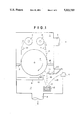
- FIG. 1 is a schematic cross-sectional view showing a depositing apparatus for manufacturing a magnetic recording medium in accordance with an embodiment of the present invention
- FIG. 2 is schematic cross-sectional view showing an ozone treatment apparatus.
- a depositing apparatus has a non-magnetic base feed-and-take-up chamber 1 and a film-forming chamber 2 which are separated from each other by a pair of partition walls 18 and 19 and a cooling can 7 disposed between the partition walls 18 and 19.
- a non-magnetic base 6 wound around a feed roller 5 disposed in the non-magnetic base feed-and-take-up chamber 1 is unrolled from the feed roller 5 and taken up by a take-up roller 8 while passing by a roller 17, the side surface of the cooling can 7 facing to the film-forming chamber 2 and a roller 21.
- the chambers 1 and 2 are evacuated to a predetermined degree of vacuum through evacuation ports 3 and 4.
- a crucible 12 is disposed in the film-forming chamber 2 and ferromagnetic metal 13 containing therein Co is placed in the crucible 12.
- the ferromagnetic metal 13 is heated to melt and evaporate by an electron beam 15 emitted from an electron gun 14, and a vapor flow 16 of the metal 13 is caused to impinge upon the non-magnetic base 6 on the cooling can 7.
- An intercept plate 9 intercepts a part of the vapor flow 16 which impinges upon the non-magnetic base 6 at an angle of incidence smaller than a predetermined value. The angle of incidence is the angle which the vapor flow 16 makes with the normal to the cooling can 7.
- Oxidizing gas is introduced into the film-forming chamber 2 toward the non-magnetic base 6 together with the vapor flow 16 from gas introduction ports 10 and 11 which are provided respectively on the low incident angle side and the high incident angle side.
- oxygen, nitrous oxide, ozone or mixture of these gas with inert gas such as argon, nitrogen or the like may be used. It is preferred that mixture of oxygen and argon or nitrogen be used as the oxidizing gas.
- the amount of the oxidizing gas depends upon the conveying speed and the width of the non-magnetic base 6, an excessively large amount and an excessively small amount of oxidizing gas both can result in deterioration of magnetic properties.
- the oxidizing gas be introduced from the port 11 in a direction which makes with the normal to the cooling can 7 an angle which is larger than the average ( ⁇ max+ ⁇ min)/2 of the maximum angle ⁇ max of incidence of the vapor flow 17 and the minimum angle ⁇ min of the same.
- the ferromagnetic metal thin-film thus obtained may be subjected to surface treatment for the purpose of oxidization and/or passivation.
- An especially preferable treatment is an ozone treatment in which the ferromagnetic metal thin-film is exposed to an ozone-containing atmosphere.
- the temperature at which the ferromagnetic metal thin-film is kept, the ozone concentration in the atmosphere, the treating time and the like should be controlled.
- the temperature at which the ferromagnetic metal thin-film should be kept though there is no specific critical point, if the ferromagnetic metal thin-film is kept at a room temperature, the treatment must be effected at a high ozone concentration for a long time, which is not preferable in view of efficiency.
- the higher the temperature is the better the result is, but when the temperature is not lower than 140° C., the non-magnetic base can be adversely affected. Further when the temperature is not lower than 140° C., the inverse cupping of the magnetic tape can become too large and the magnetic head cannot contact with the magnetic tape in a satisfactory manner.
- the ferromagnetic metal thin-film is preferably kept at 80° to 140° C. during the ozone treatment.
- the resistance to attack by salts of the ferromagnetic thin-film can be remarkably improved by setting the former and the latter so that the product of them becomes not smaller than 150000, i.e., xy ⁇ 150000.
- the surface of the ferromagnetic metal thin-film should be cleaned prior to the ozone treatment. If the surface of the ferromagnetic metal thin-film is stained, a part of the ozone is consumed in removing the staining material and the effect inherent to the ozone treatment cannot be sufficiently obtained.
- the cleanness of the surface of the ferromagnetic metal thin-film can be controlled, for instance, by water contact angle, and it is preferred that the surface of the ferromagnetic metal thin-film be cleaned to such a degree that the water contact angle is not larger than 60° prior to the ozone treatment.
- an atmosphere of dry air added with ozone or an atmosphere of inert gas, e.g., nitrogen, argon, herium or the like, added with ozone may be used for instance.
- inert gas e.g., nitrogen, argon, herium or the like
- the ozone treatment can be effected by keeping the ferromagnetic metal thin-film for a predetermined time in a treating chamber filled with the ozone-containing atmosphere, and may be either a batch process or a continuous process.
- FIG. 2 shows an example of a batch process ozone treating system.
- the treating system comprises a base plate 107 and a casing 104 placed on the base plate 107.
- a hot plate 106 is disposed in the treating chamber defined by the casing 104 and the base plate 107.
- a sample 105 (a metal thin-film magnetic recording medium comprising a non-magnetic base and a ferromagnetic metal thin-film formed thereon) is fixed to the hot plate 106 so that the ferromagnetic metal thin-film faces upward and is kept at a predetermined temperature by the hot plate 106.
- Oxygen is introduced from an oxygen reservoir into an ozonizer 102, and oxygen gas partly ozonized is introduced into the treating chamber through an introduction pipe 103, whereby the sample 105 is subjected to ozone treatment.
- the oxygen gas partly ozonized is discharged through a discharge pipe 108 to a catalytic decomposer 109 and the ozone contained therein is decomposed.
- the film-forming chamber 2 was initially evacuated to 1 ⁇ 10 -5 Torr, and a non-magnetic base of polyethylene terephthalate in continuous length was fed from the feed roller 5 toward the take-up roll 8 at a speed of 15 m/min.
- the non-magnetic base was 10 ⁇ m in thickness and 100 mm in width.
- Oxygen gas was introduced through the gas introduction ports 10 and 11 at 600 ml/min and 1200 ml/min, respectively. In this manner, a Co--Ni alloy ferromagnetic metal thin-film was formed on the non-magnetic base 6.
- the thickness of the thin-film was 0.17 ⁇ m.
- the minimum angle of incidence was set at 35°.
- the magnetic recording medium thus obtained was cut into a sample 80 mm square and the sample was subjected to the ozone treatment using the batch process ozone treating system shown in FIG. 2, thereby obtaining a final sample.
- the ozone concentration in the treating chamber was 28000 ppm, the sample was kept at 120° C. by the hot plate 106 and the treating time was 30 seconds.
- a final sample was obtained in the same manner as example 1 except that the sample was kept at 140° C.
- a final sample was obtained in the same manner as example 1 except that the ozone concentration in the treating chamber was 98000 ppm and the treating time was 10 seconds.
- a final sample was obtained in the same manner as example 1 except that the sample was not subjected to the ozone treatment.
- a final sample was obtained in the same manner as example 1 except that the sample was kept at 50° C.
- a final sample was obtained in the same manner as example 1 except that the ozone concentration in the treating chamber was 5000 ppm and the treating time was 10 seconds.
- a final sample was obtained in the same manner as example 1 except that the ozone concentration in the treating chamber was 98000 ppm, the sample was kept at 140° C. and the treating time was 3 minutes.
- a final sample was obtained in the same manner as example 1 except that oxygen gas was introduced through the gas introduction ports 10 and 11 at 250 ml/min and 500 ml/min, respectively.
- the crystal ratio, oxygen content and Y-output of the final samples were measured and the resistance to oxygen attack was evaluated.
- the measuring conditions were as follows.
- X-ray source Cu Anode, 50 kV, 180 mA
Landscapes
- Chemical & Material Sciences (AREA)
- Chemical Kinetics & Catalysis (AREA)
- Engineering & Computer Science (AREA)
- Materials Engineering (AREA)
- Mechanical Engineering (AREA)
- Metallurgy (AREA)
- Organic Chemistry (AREA)
- Physics & Mathematics (AREA)
- Spectroscopy & Molecular Physics (AREA)
- Magnetic Record Carriers (AREA)
- Compositions Of Macromolecular Compounds (AREA)
- Manufacturing Of Magnetic Record Carriers (AREA)
Abstract
Description
______________________________________
1 point  rust can be found by the naked eyes
         substantially over the entire area
2 point  rust can be found by the naked eyes
3 point  rust cannot be found by the naked eyes but
         substantial amount of rust can be found through
         the optical microscope
4 point  rust cannot be found by the naked eyes but a
         small amount of rust can be found through the
         optical microscope
5 point  rust can be found neither by the naked eyes or
         through the optical microscope
______________________________________
______________________________________
              resistance to
                         Y-output oxygen con-
CoOOH/CoO     corrosion  (dB)     tent (at %)
______________________________________
ex. 1 0.071       5          -0.2   22.1
ex. 2 0.032       5          -0.5   23.4
ex. 3 0.027       5          -0.5   24.0
con. 1
      0.213       1          0      18.7
con. 2
      0.145       2          0.1    19.3
con. 3
      0.189       1          -0.2   19.0
con. 4
      0.001       5          -2.9   27.1
con. 5
      0.121       3          0.3    13.6
______________________________________
Claims (7)
Applications Claiming Priority (2)
| Application Number | Priority Date | Filing Date | Title |
|---|---|---|---|
| JP2-238325 | 1990-09-07 | ||
| JP2238325A JP2623160B2 (en) | 1990-09-07 | 1990-09-07 | Magnetic recording media |
Publications (1)
| Publication Number | Publication Date |
|---|---|
| US5322733A true US5322733A (en) | 1994-06-21 |
Family
ID=17028534
Family Applications (1)
| Application Number | Title | Priority Date | Filing Date |
|---|---|---|---|
| US07/755,937 Expired - Lifetime US5322733A (en) | 1990-09-07 | 1991-09-06 | Magnetic recording medium |
Country Status (2)
| Country | Link |
|---|---|
| US (1) | US5322733A (en) |
| JP (1) | JP2623160B2 (en) |
Cited By (3)
| Publication number | Priority date | Publication date | Assignee | Title |
|---|---|---|---|---|
| US20090075016A1 (en) * | 2005-05-17 | 2009-03-19 | Yuuko Tomekawa | Multilayer information recording medium and production method therefor |
| US20120183811A1 (en) * | 2011-01-17 | 2012-07-19 | Fujifilm Corporation | Magnetic recording medium |
| WO2012146310A1 (en) * | 2011-04-29 | 2012-11-01 | Applied Materials, Inc. | Devices and methods for passivating a flexible substrate in a coating process |
Families Citing this family (1)
| Publication number | Priority date | Publication date | Assignee | Title |
|---|---|---|---|---|
| JPH06111272A (en) * | 1992-08-14 | 1994-04-22 | Matsushita Electric Ind Co Ltd | Magnetic recording medium and its manufacture |
Citations (7)
| Publication number | Priority date | Publication date | Assignee | Title |
|---|---|---|---|---|
| JPS5615014A (en) * | 1979-07-18 | 1981-02-13 | Matsushita Electric Ind Co Ltd | Metallic thin film type magnetic recording medium |
| JPS5779951A (en) * | 1980-11-06 | 1982-05-19 | Canon Inc | Developer |
| JPS60160027A (en) * | 1984-01-31 | 1985-08-21 | Sony Corp | Magnetic recording medium |
| US4567116A (en) * | 1983-08-06 | 1986-01-28 | Canon Kabushiki Kaisha | Magnetic recording medium |
| US4596735A (en) * | 1983-04-30 | 1986-06-24 | Tdk Corporation | Magnetic recording medium and method for making |
| JPS62275316A (en) * | 1985-04-15 | 1987-11-30 | Hitachi Maxell Ltd | Magnetic recording medium and its production |
| US4711810A (en) * | 1984-10-29 | 1987-12-08 | Victor Company Of Japan, Ltd. | Magnetic medium for horizontal magnetization recording and method for making same |
-
1990
- 1990-09-07 JP JP2238325A patent/JP2623160B2/en not_active Expired - Fee Related
-
1991
- 1991-09-06 US US07/755,937 patent/US5322733A/en not_active Expired - Lifetime
Patent Citations (9)
| Publication number | Priority date | Publication date | Assignee | Title |
|---|---|---|---|---|
| US4323629A (en) * | 1979-07-17 | 1982-04-06 | Matsushita Electric Industrial Co., Ltd. | Metallic thin film magnetic recording medium |
| JPS5615014A (en) * | 1979-07-18 | 1981-02-13 | Matsushita Electric Ind Co Ltd | Metallic thin film type magnetic recording medium |
| JPS5779951A (en) * | 1980-11-06 | 1982-05-19 | Canon Inc | Developer |
| US4596735A (en) * | 1983-04-30 | 1986-06-24 | Tdk Corporation | Magnetic recording medium and method for making |
| US4567116A (en) * | 1983-08-06 | 1986-01-28 | Canon Kabushiki Kaisha | Magnetic recording medium |
| JPS60160027A (en) * | 1984-01-31 | 1985-08-21 | Sony Corp | Magnetic recording medium |
| US4711810A (en) * | 1984-10-29 | 1987-12-08 | Victor Company Of Japan, Ltd. | Magnetic medium for horizontal magnetization recording and method for making same |
| JPS62275316A (en) * | 1985-04-15 | 1987-11-30 | Hitachi Maxell Ltd | Magnetic recording medium and its production |
| US5073449A (en) * | 1985-04-15 | 1991-12-17 | Hitachi Maxell Ltd. | Magnetic recording medium and method for producing the same |
Non-Patent Citations (2)
| Title |
|---|
| "Japanese Applied Magnetics Academy Transactions" vol. 14, No. 2, 1990, pp. 251-256. |
| Japanese Applied Magnetics Academy Transactions vol. 14, No. 2, 1990, pp. 251 256. * |
Cited By (7)
| Publication number | Priority date | Publication date | Assignee | Title |
|---|---|---|---|---|
| US20090075016A1 (en) * | 2005-05-17 | 2009-03-19 | Yuuko Tomekawa | Multilayer information recording medium and production method therefor |
| US7854819B2 (en) * | 2005-05-17 | 2010-12-21 | Panasonic Corporation | Multilayer information recording medium and production method therefor |
| US20120183811A1 (en) * | 2011-01-17 | 2012-07-19 | Fujifilm Corporation | Magnetic recording medium |
| WO2012146310A1 (en) * | 2011-04-29 | 2012-11-01 | Applied Materials, Inc. | Devices and methods for passivating a flexible substrate in a coating process |
| CN103502506A (en) * | 2011-04-29 | 2014-01-08 | 应用材料公司 | Devices and methods for passivating a flexible substrate in a coating process |
| CN103502506B (en) * | 2011-04-29 | 2016-06-08 | 应用材料公司 | For being passivated the apparatus and method of flexible base board in coating processes |
| EP3441503A1 (en) * | 2011-04-29 | 2019-02-13 | Applied Materials, Inc. | Devices and methods for passivating a flexible substrate in a coating process |
Also Published As
| Publication number | Publication date |
|---|---|
| JP2623160B2 (en) | 1997-06-25 |
| JPH04119516A (en) | 1992-04-21 |
Similar Documents
| Publication | Publication Date | Title |
|---|---|---|
| US5914151A (en) | Method for forming silica protective films | |
| US5322733A (en) | Magnetic recording medium | |
| US4801500A (en) | Magnetic recording medium | |
| US4673610A (en) | Magnetic recording medium having iron nitride recording layer | |
| US4766034A (en) | Magnetic recording medium | |
| JP2662777B2 (en) | Magnetic recording medium and method of manufacturing the same | |
| US4876113A (en) | Method for producing magnetic recording media | |
| JPH0223926B2 (en) | ||
| JP2714698B2 (en) | Magnetic recording media | |
| US5914180A (en) | Magnetic recording medium | |
| JP2554277B2 (en) | Magnetic recording media | |
| US4923748A (en) | Magnetic recording medium | |
| JPH0475577B2 (en) | ||
| US5378496A (en) | Method of manufacturing magnetic recording medium | |
| JPS6154041A (en) | Manufacture of magnetic recording medium | |
| JPH05143968A (en) | Magnetic recording medium and production thereof | |
| JPH04283912A (en) | Manufacture of magnetic recording medium | |
| US4956229A (en) | Magnetic recording medium | |
| JPH03201217A (en) | Production of magnetic recording medium | |
| JPS59188825A (en) | magnetic recording medium | |
| JP2002269724A (en) | Magnetic recording media | |
| JPH0520809B2 (en) | ||
| JPS6113437A (en) | Magnetic recording medium | |
| JPS63136319A (en) | Production of magnetic recording medium | |
| JPS6182323A (en) | Magnetic recording medium |
Legal Events
| Date | Code | Title | Description |
|---|---|---|---|
| AS | Assignment |
Owner name: FUJI PHOTO FILM CO., LTD., JAPAN Free format text: ASSIGNMENT OF ASSIGNORS INTEREST.;ASSIGNORS:DOUSHITA, HIROAKI;YASUNAGA, TADASHI;REEL/FRAME:005837/0912 Effective date: 19910904 |
|
| STCF | Information on status: patent grant |
Free format text: PATENTED CASE |
|
| FEPP | Fee payment procedure |
Free format text: PAYOR NUMBER ASSIGNED (ORIGINAL EVENT CODE: ASPN); ENTITY STATUS OF PATENT OWNER: LARGE ENTITY |
|
| FPAY | Fee payment |
Year of fee payment: 4 |
|
| FEPP | Fee payment procedure |
Free format text: PAYER NUMBER DE-ASSIGNED (ORIGINAL EVENT CODE: RMPN); ENTITY STATUS OF PATENT OWNER: LARGE ENTITY Free format text: PAYOR NUMBER ASSIGNED (ORIGINAL EVENT CODE: ASPN); ENTITY STATUS OF PATENT OWNER: LARGE ENTITY |
|
| FPAY | Fee payment |
Year of fee payment: 8 |
|
| FPAY | Fee payment |
Year of fee payment: 12 |
|
| AS | Assignment |
Owner name: FUJIFILM CORPORATION, JAPAN Free format text: ASSIGNMENT OF ASSIGNORS INTEREST;ASSIGNOR:FUJIFILM HOLDINGS CORPORATION (FORMERLY FUJI PHOTO FILM CO., LTD.);REEL/FRAME:018904/0001 Effective date: 20070130 Owner name: FUJIFILM CORPORATION,JAPAN Free format text: ASSIGNMENT OF ASSIGNORS INTEREST;ASSIGNOR:FUJIFILM HOLDINGS CORPORATION (FORMERLY FUJI PHOTO FILM CO., LTD.);REEL/FRAME:018904/0001 Effective date: 20070130 |