US532207A - Coffee-roaster - Google Patents
Coffee-roaster Download PDFInfo
- Publication number
- US532207A US532207A US532207DA US532207A US 532207 A US532207 A US 532207A US 532207D A US532207D A US 532207DA US 532207 A US532207 A US 532207A
- Authority
- US
- United States
- Prior art keywords
- cylinder
- opening
- plate
- plates
- coffee
- Prior art date
- Legal status (The legal status is an assumption and is not a legal conclusion. Google has not performed a legal analysis and makes no representation as to the accuracy of the status listed.)
- Expired - Lifetime
Links
- 230000033001 locomotion Effects 0.000 description 5
- 239000002184 metal Substances 0.000 description 5
- 229910052751 metal Inorganic materials 0.000 description 5
- 229910001018 Cast iron Inorganic materials 0.000 description 2
- 238000010276 construction Methods 0.000 description 2
- 229910000831 Steel Inorganic materials 0.000 description 1
- 238000013019 agitation Methods 0.000 description 1
- 230000003467 diminishing effect Effects 0.000 description 1
- 238000010438 heat treatment Methods 0.000 description 1
- 239000000463 material Substances 0.000 description 1
- 230000003534 oscillatory effect Effects 0.000 description 1
- 239000010959 steel Substances 0.000 description 1
- 238000005728 strengthening Methods 0.000 description 1
Images
Classifications
-
- A—HUMAN NECESSITIES
- A23—FOODS OR FOODSTUFFS; TREATMENT THEREOF, NOT COVERED BY OTHER CLASSES
- A23N—MACHINES OR APPARATUS FOR TREATING HARVESTED FRUIT, VEGETABLES OR FLOWER BULBS IN BULK, NOT OTHERWISE PROVIDED FOR; PEELING VEGETABLES OR FRUIT IN BULK; APPARATUS FOR PREPARING ANIMAL FEEDING- STUFFS
- A23N12/00—Machines for cleaning, blanching, drying or roasting fruits or vegetables, e.g. coffee, cocoa, nuts
- A23N12/08—Machines for cleaning, blanching, drying or roasting fruits or vegetables, e.g. coffee, cocoa, nuts for drying or roasting
- A23N12/10—Rotary roasters
Definitions
- the invention is related to that class of ole is revolnbly mounted over a stove or other source of heat, and adapted to contain the cofiee to be roasted, and to be revolved dur- 7 ing the roasting operation; and the purpose of this invention is to so improve the construction of this class of devices that the cofiee may be roasted in a better manner and that the device will be more durable and efficient and capable of easier manipulation.
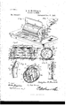
- Figure 1 represents a perspective view of my improvements, showing them applied to a stove and in the position when in use;
- Fig. 2, a longisection thereofyFig; 4, an enlarged section illustrating the catch for holding thedoor of the cylinder in placepFig. 5, a; detail view illustrating the spring for automatically opening the door;
- Fig. 6, a side elevation of one of the bearings for mounting the cylinder of my invention;
- Fig. 7, a detail perspective of one of the cleats for securing to the main plate of the device.
- the reference numeral 1 indicates the base portion of my improvements, which base consists of a rectangular metallic plate formed with the correspondingly-shaped opening 2 therein. This opening is of a size equal to about two-thirds that of the base 1, and is formed to permit the passage of heat from the interior of the stove to the cylinder.
- the semicircular cleats 3 which have their plane edges projecting a slight distance into the opening 2 and formed with a groove 4 therein.
- These grooves are curved in the arc of a circle and are arranged directly adjacent to the grooves 5, which are correspondingly curved and which are formed in the plate .1, and at the ,ends of the opening 2.
- the opening 2 has at each 'end thereof a curved or semicircular groove, and these grooves are respectively adapted for the reception of the ends of the deflector-plates 6.
- the deflector plates, 6, are two in number and are curved in conformity with the arc of the grooves 4 and 5, so that they, the plates 6, .will be capable of movement within said grooves and of being adjusted therein.
- the purpose of the plates 6 is to regulate the amount of heat which passes through the opening2, and this may be effected by moving the plates toward and from each other,
- buttons 7 are eccentrically tudinal section of the roaster; Fig. 3, a cross-,
- the bearings 8 Rigidly secured to the upper sideof the r plate 1, and arising. vertically therefrom, are the bearings 8, which are provided with the strengthening and bracing ribs 9, whereby theirrigidity is secured.
- the bearings 8 are longitudinallyand centrally aligned on the base 1 and are formed of plates of metal having in one side thereof the diagonally-extending grooves 10.
- the grooves 10 are preferably threein number, though this may be variously changed, and they have theirinner 9o ends terminating in the center of the plate composing the hearing.
- the purpose of the bearing 8 is to revolubly mount the cylinder of my machine, and in order that the trunnions thereof may be securely held in place, 5 Iprovide the swinging link 11, which is pivotally connected to the plate at a point just below the lowest slot 10, and which is capable of swinging upwardly and ofembracing the upper end of the plate 8, so as to inclose the ICC slots 10 and thereby prevent outward movement of the trunnions which may be j onrnaled therein.
- the links 11 are capable of being easily moved out of engagement with the upper end of the plates 8, so as to open the slots and make it possible for the trunnions therein to be removed.
- the purpose for this removal will be hereinafter explained.
- 12 indicates the aforesaid cylinder of my invention, and thislprefer to form of the cast-iron heads 13, having the internal rabbet-grooves 14, formed on their peripheries, in which grooves the sheet metal plate 15 is arranged, and held in place by bolts or screws 16.
- Extending centrally and longitudinally through the cylinder 12 is the axle 17, which passes through the centers of heads 13, and which is formed with the extended ends 18.
- the cylinder 12 is provided with an opening 21, through which the cofiee to be roasted is passed.
- This opening is provided with a door 22, consisting of a sheet of metal curved in conformity with the circumference of the cylinder and provided with the lugs 22*, perforated longitudinally so as to receive the rod 23.
- the rod 23 extends from one end to the other of the cylinder, and is secured therein so that the door will be capable of oscillatory move ment on it.
- the lugs or bearings 22 are arranged at a point between thesides of the 1 12, and adjacent to the opening 21, is the spring-catch 24, which is arranged in the internal groove 25 of the cylinder, and which projects into the space occupied by said opening.
- This catch is adapted to engage with the rib 26, secured to the inner side of the lid and directly adjacent to the side of the opening 21, to which the catch is secured, so that, when the lid is moved in place, the two parts will engage and operate to secure the lid in place.
- Any device capable of passing the opening and engaging the catch will be suitable for this purpose.
- this spring 29 indicates a spring, which I provide for giving the door 22 anormal tendency to open, and this spring consists of a bar or rod of steel rigidly secured to one of the heads 13 at the point 30, and projecting to the pin 31, around which it is coiled. From the pin 31 the spring extends approximately radially to the plane of opening 21, where it is provided with the curved end 32, adapted to engage with the under side of the lid and to press it outwardly. As the lid is closed, the normal tendency of the spring 29 will be overcome, but as the catch 24 is disengaged the spring will be allowed to operate and 'will cause the door to fly open. Rigidly secured to the interior.
- the longitudinal ribs 33 which have for their purpose to agitate the coffee within the cylinder. This agitation is efiected owing to well-known principles. As the cylinder revolves, a portion of the coffee will rest upon the ribs and be carried partially up, only to drop therefrom as the height of the rib becomes so great that it will no longer furnish a horizontal portion upon which the colfee may rest.
- bail 34 indicates a bail or handle, which consists of a piece of wire bent to form a horizontallyextending portion by which it may be grasped, and having its ends formed into the vertical portions 35, and books 36.
- the hooks 36 are adapted to embrace the trunnions 18, and to lie within the annular grooves 37, formed in said trunnions and directly adjacent to the heads 13 of the cylinder.
- the purpose of this bail is to furnish a means for lifting the cylinder off the stove directly after the roasting operation, so that it may be revolved away from the stove to cool itand its contents.
- the lid 22 is opened and the coffee to be roasted inserted within the cylinder, after which the lid should be closed and fastened as explained.
- the cylinder should now be mounted in the bearings 8 and the links 11 operated to in'close the slots 10 thereof.
- the base-plate 1 should now be placed on the stove, and preferably within the openings formed for the reception of the usual lids.
- the base-plate I have formed the cleats 3 with the Y curved outer edges referred to before, whereby the plate may be seated upon the top of the stove and the cleats 3 allowed to pass within the lid-openings or eyes, and with their curved edges in engagement with the inner edges of the openings, thus making a snug connection.
- the cylinder may be revolved while suscurved so that they will conform to the curvature of cylinder 12, and so that their lower ends will occur adjacent to and nearly in engagement with the lower end of the cylinder.
- the purpose of this construction is to secure an approximately tight joint and to make the operation of the plates more efiective.
- a base-plate adapted to be mounted over the fire and having formed therein an opening through which the heat may pass, said opening having formed at its ends a groove curved in the arc of a circle, two deflector-plates arranged with their ends in said grooves and curved in conformity therewith, whereby they may be moved toward and from each other so as to regulate the size of the opening through which the heat may pass and a cylinder revolubly mounted in the base plate and having its lower side arranged in the opening, said cylinder being adapted to receive the coffee to be. roasted, substantially as described.
Landscapes
- Life Sciences & Earth Sciences (AREA)
- Chemical & Material Sciences (AREA)
- Engineering & Computer Science (AREA)
- Food Science & Technology (AREA)
- Polymers & Plastics (AREA)
- Cookers (AREA)
Description
(N0 ModeL}.
D. H. MARSHALL. GOFFEE ROASTER.
No. 532,207. Patented Jan. 8,1895,
13 Al' mmn I v v THE "hams PlTiRS m. pgcrro-um'ov. wAsmNsTON n c coffee-masters wherein a cylindrical recepta- UNITED STATES.
PATENT OFFICE;
DoUe ss H. MARsIIALL, or STEVENS CREEK; VIRGINIA.
COFFEEI-ROASTER.
SPECIFICATION forming part of Letters Patent No. 532,207, dated January 8, 1895 A licant]; filed June18,1 89f1giSerial No. 514,975. (No model.)
To all whom, it may concern:-
Be it known thatLgDouo Ass H. MAR- SHALL, a citizen of the United States, residing at Stevens Creek, in the county of Grayson and State of Virginia, have invented a new and useful Coffee-Roaster, of which the-following is a specification.
The invention is related to that class of ole is revolnbly mounted over a stove or other source of heat, and adapted to contain the cofiee to be roasted, and to be revolved dur- 7 ing the roasting operation; and the purpose of this invention is to so improve the construction of this class of devices that the cofiee may be roasted in a better manner and that the device will be more durable and efficient and capable of easier manipulation.
In the accompanying drawings: Figure 1 represents a perspective view of my improvements, showing them applied to a stove and in the position when in use; Fig. 2, a longisection thereofyFig; 4, an enlarged section illustrating the catch for holding thedoor of the cylinder in placepFig. 5, a; detail view illustrating the spring for automatically opening the door; Fig. 6, a side elevation of one of the bearings for mounting the cylinder of my invention; Fig. 7, a detail perspective of one of the cleats for securing to the main plate of the device.
The reference numeral 1 indicates the base portion of my improvements, which base consists of a rectangular metallic plate formed with the correspondingly-shaped opening 2 therein. This opening is of a size equal to about two-thirds that of the base 1, and is formed to permit the passage of heat from the interior of the stove to the cylinder.
.Formed integral with, or rigidly secured to,
the lower side of the plate 1, and at each end thereof, are the semicircular cleats 3, which have their plane edges projecting a slight distance into the opening 2 and formed with a groove 4 therein. These grooves are curved in the arc of a circle and are arranged directly adjacent to the grooves 5, which are correspondingly curved and which are formed in the plate .1, and at the ,ends of the opening 2.
\ Thus itwill be seen that the opening 2 has at each 'end thereof a curved or semicircular groove, and these grooves are respectively adapted for the reception of the ends of the deflector-plates 6.
The deflector plates, 6, are two in number and are curved in conformity with the arc of the grooves 4 and 5, so that they, the plates 6, .will be capable of movement within said grooves and of being adjusted therein.
The purpose of the plates 6 is to regulate the amount of heat which passes through the opening2, and this may be effected by moving the plates toward and from each other,
an'd'in and out of the grooves 4 and 5; thereby increasing or diminishing the size of the opening through which the heat may pass. Pivotally secured to the outer sides of the plates Be are the butt nsZ-Whichare provided to holdthe plates in place, and this is done by Eswinging them, so that they willengage the 1 upper surface of the base or plate Land in so 7 1 doing prevent further inward movement of 1 plate 6. The buttons 7 are eccentrically tudinal section of the roaster; Fig. 3, a cross-,
Rigidly secured to the upper sideof the r plate 1, and arising. vertically therefrom, are the bearings 8, which are provided with the strengthening and bracing ribs 9, whereby theirrigidity is secured. ,The bearings 8 are longitudinallyand centrally aligned on the base 1 and are formed of plates of metal having in one side thereof the diagonally-extending grooves 10. The grooves 10 are preferably threein number, though this may be variously changed, and they have theirinner 9o ends terminating in the center of the plate composing the hearing. The purpose of the bearing 8 is to revolubly mount the cylinder of my machine, and in order that the trunnions thereof may be securely held in place, 5 Iprovide the swinging link 11, which is pivotally connected to the plate at a point just below the lowest slot 10, and which is capable of swinging upwardly and ofembracing the upper end of the plate 8, so as to inclose the ICC slots 10 and thereby prevent outward movement of the trunnions which may be j onrnaled therein.
It will be observed that the links 11 are capable of being easily moved out of engagement with the upper end of the plates 8, so as to open the slots and make it possible for the trunnions therein to be removed. The purpose for this removal will be hereinafter explained. 12 indicates the aforesaid cylinder of my invention, and thislprefer to form of the cast-iron heads 13, having the internal rabbet-grooves 14, formed on their peripheries, in which grooves the sheet metal plate 15 is arranged, and held in place by bolts or screws 16. Extending centrally and longitudinally through the cylinder 12 is the axle 17, which passes through the centers of heads 13, and which is formed with the extended ends 18. These ends 18 operate to form the trunnions or journals for revolubly mounting the cylinder, and to this end they are provided with the annular grooves 19, of a size sufficient to reduce the diameter of the axle to a degree commensurate with the size of the slots 10, whereby the two parts maybe easily fitted together, and whereby they may be mounted so that the cylinder will be capable of easy revolution.
One end of the axle 17 is extended even beyond the trunnions 18, so as to provide means for attaching the crank-arm 20, by which the movement characteristic of the cylinder 12 is imparted thereto. The cylinder 12 is provided with an opening 21, through which the cofiee to be roasted is passed. This opening is provided with a door 22, consisting of a sheet of metal curved in conformity with the circumference of the cylinder and provided with the lugs 22*, perforated longitudinally so as to receive the rod 23. The rod 23 extends from one end to the other of the cylinder, and is secured therein so that the door will be capable of oscillatory move ment on it. The lugs or bearings 22 are arranged at a point between thesides of the 1 12, and adjacent to the opening 21, is the spring-catch 24, which is arranged in the internal groove 25 of the cylinder, and which projects into the space occupied by said opening. This catch is adapted to engage with the rib 26, secured to the inner side of the lid and directly adjacent to the side of the opening 21, to which the catch is secured, so that, when the lid is moved in place, the two parts will engage and operate to secure the lid in place.
Formed on the cylinder, and directly adjacent to the opening 21, is the passage 27, which is directly adjacent to the catch 24, and which is provided for the passage of an instrument so as to press the catch out of engagement with the rib 26, and allow the door to be opened. Any device capable of passing the opening and engaging the catch will be suitable for this purpose.
29 indicates a spring, which I provide for giving the door 22 anormal tendency to open, and this spring consists of a bar or rod of steel rigidly secured to one of the heads 13 at the point 30, and projecting to the pin 31, around which it is coiled. From the pin 31 the spring extends approximately radially to the plane of opening 21, where it is provided with the curved end 32, adapted to engage with the under side of the lid and to press it outwardly. As the lid is closed, the normal tendency of the spring 29 will be overcome, but as the catch 24 is disengaged the spring will be allowed to operate and 'will cause the door to fly open. Rigidly secured to the interior. of the cylinder 12, and at" equidistant points thereon, are the longitudinal ribs 33, which have for their purpose to agitate the coffee within the cylinder. This agitation is efiected owing to well-known principles. As the cylinder revolves, a portion of the coffee will rest upon the ribs and be carried partially up, only to drop therefrom as the height of the rib becomes so great that it will no longer furnish a horizontal portion upon which the colfee may rest.
34 indicates a bail or handle, which consists of a piece of wire bent to form a horizontallyextending portion by which it may be grasped, and having its ends formed into the vertical portions 35, and books 36. The hooks 36 are adapted to embrace the trunnions 18, and to lie within the annular grooves 37, formed in said trunnions and directly adjacent to the heads 13 of the cylinder. The purpose of this bail is to furnish a means for lifting the cylinder off the stove directly after the roasting operation, so that it may be revolved away from the stove to cool itand its contents.
In the use of my invention, the lid 22 is opened and the coffee to be roasted inserted within the cylinder, after which the lid should be closed and fastened as explained. The cylinder should now be mounted in the bearings 8 and the links 11 operated to in'close the slots 10 thereof. The base-plate 1 should now be placed on the stove, and preferably within the openings formed for the reception of the usual lids. In order to facilitate this use of the base-plate I have formed the cleats 3 with the Y curved outer edges referred to before, whereby the plate may be seated upon the top of the stove and the cleats 3 allowed to pass within the lid-openings or eyes, and with their curved edges in engagement with the inner edges of the openings, thus making a snug connection. It will be understood that the usual plate which is arranged between each pair of lids should be first removed. I The deflector-plates should now be adjusted to suit the degree of heat which it is desired should influence the cylinder 12, and when this has been done, the cylinder should be revolved by means of crank 20, so as to agitate the coifee, and to insure the equal heating thereof. After the coffee has been roasted sufficiently the links 11 should be disengaged from the upper end of the plates V m. J
10, and the cylinder removed from said plates, and this by means of the bail 34. If so desired, the cylinder may be revolved while suscurved so that they will conform to the curvature of cylinder 12, and so that their lower ends will occur adjacent to and nearly in engagement with the lower end of the cylinder. The purpose of this construction is to secure an approximately tight joint and to make the operation of the plates more efiective.
While I have described the cylinder 12 as formed of cast iron heads with sheet metal sides, it will be understood that I reserve the right to change the material or its form whenever desired. For example, the whole cylinder could be formed of cast metal, and in practice may be so formed.
Having described the invention, What I claim is- In a coffee-roaster, the combination of a base-plate adapted to be mounted over the fire and having formed therein an opening through which the heat may pass, said opening having formed at its ends a groove curved in the arc of a circle, two deflector-plates arranged with their ends in said grooves and curved in conformity therewith, whereby they may be moved toward and from each other so as to regulate the size of the opening through which the heat may pass and a cylinder revolubly mounted in the base plate and having its lower side arranged in the opening, said cylinder being adapted to receive the coffee to be. roasted, substantially as described.
-In testimony that I claim the foregoing as my own I- have hereto affixed my signature in the presence of two witnesses.
DOUGLASS H. MARSHALL.
Witnesses:
THOS. L. HILL, JOHN W. BOYLES.
Publications (1)
| Publication Number | Publication Date |
|---|---|
| US532207A true US532207A (en) | 1895-01-08 |
Family
ID=2600979
Family Applications (1)
| Application Number | Title | Priority Date | Filing Date |
|---|---|---|---|
| US532207D Expired - Lifetime US532207A (en) | Coffee-roaster |
Country Status (1)
| Country | Link |
|---|---|
| US (1) | US532207A (en) |
-
0
- US US532207D patent/US532207A/en not_active Expired - Lifetime
Similar Documents
| Publication | Publication Date | Title |
|---|---|---|
| US532207A (en) | Coffee-roaster | |
| US616964A (en) | Rotary corn-popper or coffee-roaster | |
| US769745A (en) | Broiler. | |
| US38018A (en) | Improvement in broilers | |
| US169498A (en) | Improvement in coffee-roasters | |
| US401560A (en) | Edward hotchkiss | |
| US106288A (en) | bunyan | |
| US186176A (en) | Improvement in combined flat-iron heater and coffee-roaster | |
| US229280A (en) | Waffle-iron | |
| US122357A (en) | Improvement in coffee-roasters | |
| US213721A (en) | Improvement in ash-sifters | |
| US452015A (en) | Grater | |
| US56861A (en) | Pascal plant | |
| US309098A (en) | O o o o o | |
| US169059A (en) | Improvement in coffee-roasters | |
| US510536A (en) | Bread-raiser | |
| US246687A (en) | Sad-iron heater | |
| US29798A (en) | Coffee-roaster | |
| US145576A (en) | Improvement in coffee-roasters | |
| US147290A (en) | Edwin shape | |
| US857812A (en) | Culinary utensil. | |
| US237018A (en) | Coffee-roaster | |
| US196225A (en) | Improvement in coffee-roasters | |
| US115657A (en) | Improvement in ice-cream freezers | |
| US430912A (en) | Stove for consuming straw |