US5321918A - Spindle grinding method and apparatus - Google Patents
Spindle grinding method and apparatus Download PDFInfo
- Publication number
- US5321918A US5321918A US07/989,712 US98971292A US5321918A US 5321918 A US5321918 A US 5321918A US 98971292 A US98971292 A US 98971292A US 5321918 A US5321918 A US 5321918A
- Authority
- US
- United States
- Prior art keywords
- spindle
- bore
- axis
- grinder
- slide
- Prior art date
- Legal status (The legal status is an assumption and is not a legal conclusion. Google has not performed a legal analysis and makes no representation as to the accuracy of the status listed.)
- Expired - Lifetime
Links
Images
Classifications
-
- B—PERFORMING OPERATIONS; TRANSPORTING
- B24—GRINDING; POLISHING
- B24B—MACHINES, DEVICES, OR PROCESSES FOR GRINDING OR POLISHING; DRESSING OR CONDITIONING OF ABRADING SURFACES; FEEDING OF GRINDING, POLISHING, OR LAPPING AGENTS
- B24B41/00—Component parts such as frames, beds, carriages, headstocks
- B24B41/04—Headstocks; Working-spindles; Features relating thereto
-
- B—PERFORMING OPERATIONS; TRANSPORTING
- B24—GRINDING; POLISHING
- B24B—MACHINES, DEVICES, OR PROCESSES FOR GRINDING OR POLISHING; DRESSING OR CONDITIONING OF ABRADING SURFACES; FEEDING OF GRINDING, POLISHING, OR LAPPING AGENTS
- B24B15/00—Machines or devices designed for grinding seat surfaces; Accessories therefor
-
- B—PERFORMING OPERATIONS; TRANSPORTING
- B24—GRINDING; POLISHING
- B24B—MACHINES, DEVICES, OR PROCESSES FOR GRINDING OR POLISHING; DRESSING OR CONDITIONING OF ABRADING SURFACES; FEEDING OF GRINDING, POLISHING, OR LAPPING AGENTS
- B24B23/00—Portable grinding machines, e.g. hand-guided; Accessories therefor
- B24B23/08—Portable grinding machines designed for fastening on workpieces or other parts of particular section, e.g. for grinding commutators
-
- B—PERFORMING OPERATIONS; TRANSPORTING
- B24—GRINDING; POLISHING
- B24B—MACHINES, DEVICES, OR PROCESSES FOR GRINDING OR POLISHING; DRESSING OR CONDITIONING OF ABRADING SURFACES; FEEDING OF GRINDING, POLISHING, OR LAPPING AGENTS
- B24B5/00—Machines or devices designed for grinding surfaces of revolution on work, including those which also grind adjacent plane surfaces; Accessories therefor
- B24B5/02—Machines or devices designed for grinding surfaces of revolution on work, including those which also grind adjacent plane surfaces; Accessories therefor involving centres or chucks for holding work
- B24B5/14—Machines or devices designed for grinding surfaces of revolution on work, including those which also grind adjacent plane surfaces; Accessories therefor involving centres or chucks for holding work for grinding conical surfaces, e.g. of centres
Definitions
- This invention relates generally to truing the bores of rotary spindles, and more particularly concerns method and apparatus for effecting said truing by grinding the spindle bore while the spindle itself is rotating.
- the method of the invention comprises:
- a) providing structure including a master plate having a surface facing the bore, the surface having a predetermined boundary to define a center,
- the structure includes a bottom slide to be movable generally normal to the spindle axis, the master plate mounted on the bottom slide to be movable therewith.
- the master plate is typically provided with a boundary or edge extending about the master plate surface, that boundary used to center the master plate relative to the spindle axis. Accordingly, a relationship is established between the master plate, the bottom slide, and the angled slide, to provide a reference locating for the grinder relative to the spindle tapered bore to be ground in place.
- the spindle grinder is set up using the master plate which establishes an X-Y plane perpendicular to the center line established by the rotation of the shaft in the spindle bearings. After the X-Y plane perpendicularity is established, the outside circumference of the master plate is swept to provide concentricity to the center line of spindle rotation. With concentricity established, the angled slide can be moved in and out to grind the spindle.
- the grinder is always working on a radian which passes through center; therefore, the X-Y plane relationship is always intact.
- a further object involves providing the boundary of the master plate to extend circularly about the master plate surface, and employing a sensor to engage the circular boundary during the d) step.
- Further objects include providing a motor drive for the rotary grinder to rotate same, and supporting the motor on the bottom slide; and moving a rotary grinding head defined by the grinder along a slant height defined by the rotary tapered bore of the spindle rotating in place to accomplish truing.
- Apparatus for grinding the spindle bore basically comprises:
- a) structure including a master plate having a surface facing the bore, the surface having a predetermined boundary (for example a circular edge) to define a center,
- the structure being adjustable to bring the master plate surface into perpendicularity to the axis and to bring its center into coincidence with that axis,
- the grinder may be operated to grind the tapered bore as the spindle is rotated and as the angled slide is moved endwise.
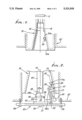
- FIG. 1 is a section taken through a spindle, the bore of which is to be ground in place;
- FIG. 2 is a schematic view of apparatus and method for accomplishing the in-place grinding of the spindle bore
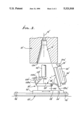
- FIG. 3 is a schematic view of a somewhat modified apparatus.
- a rotary spindle 10 is rotatable by means generally indicated at 11, to rotate about an axis 12.
- the spindle is typically used during machining, such as milling, and may receive the shaft of a milling tool, the shaft engaging the spindle tapered bore 13.
- the latter typically becomes larger at its larger end 13a in use, due to wear. Also, chips and other foreign material may become trapped at the taper and cause deformation and taper deterioration. This can lead to decreased tool life, excess vibration, out of tolerance condition of the work to be machined, and poor finish of the latter.
- method and means is provided to perform grinding of the spindle without removing it from the machine tool apparatus, i.e., in-place grinding to "true-up" the bore relative to axis 12.
- the method may be carried out using apparatus to be described, or other equivalent apparatus.
- Such apparatus includes structure, including a master plate having a surface facing the bore 13, that surface having a predetermined boundary to define a center. See for example the structure 20, which includes a bottom plate 21 supporting a bottom slide 22, slidable on the plate surface 21, in X-Y directions generally perpendicular to the Z axis direction of axis 12.
- Directions X-Y-Z define a rectangular coordinate system.
- the slide 22 may alternatively be moved in only the X direction.
- Suitable means is provided for holding the slide at its adjusted position relative to plate 21, such means indicated at 24 in two positions associated with the X and Y axes, and which may include suitable clamps which are adjustable.
- the bottom plate 21 may itself by adjustably attached to support structure or machine bed indicated at 25 and associated with 10, and may be adjustably tilted relatively to 25 at two 90° locations by means indicated generally at 26, as for example jack screws.
- the angled slide 27 is supported by mount 28a rigidly mounted at 28 on the bottom slide 22, the slide 27 being movable endwise (see arrows 33) relative to is the structure 20 and at a predetermined angle ⁇ relative to the plane of the top surface 29 of the master plate 30.
- the latter is carried at 140 by the bottom elide 22.
- the master plate 30 is movable with the bottom slide 22, since it is rigidly carried thereby, and movable in X and Y directions with 22.
- a rotary grinder 31 is carried on the angled slide 27 to be movable endwise therewith in direction 33, while the grinder head 31a is rotated about an axis 32 parallel to the direction of sliding movement of the slide 27. See arrows 33.
- a motor to rotate the head 31a is indicated at 34; and 35 indicates the slidable connection of the grinder head to move endwise in the direction of axis 32.
- the grinder head 31a is operated to engage the spindle bore 13 for grinding same to true the bore as the spindle rotates and as the head rotates, whereby the bore is concentrically trued about the axis 12.
- the structure 20 is adjustable to bring the master plate surface 29 into perpendicularity to the axis 12, and to bring the center 29a of that surface into coincidence with axis 12, after which time the grinder may be operated, as described, to true the bore.
- the master plate 30 has a boundary extending about the plate surface 29, that boundary being employed during the adjustment of the structure 20, as referred to.
- the boundary indicated at 38 extends circularly about the master plate surface, and about center 29a, whereby a sensor, including an indicator 39, may be employed to engage the circular boundary during the adjustment of the structure 20, as referred to.
- the indicator is carried by a shaft 40 associated with the spindle, that shaft having an axis coincident with axis 12. During set up, the shaft carrying the indicator is rotated about axis 12, and the indicator tip 39a engages the circular boundary, or edge 38, of the plate 30 and surface 29.
- the indicator displays no gauge movement as shaft 40 is rotated, it means that the adjustment of the structure 20 has been such as to locate surface 29 perpendicular to axis 12 and to locate edge 38 concentrically about axis 12, and to locate center 29a coincident with axis 12.
- Such adjustment includes adjustable tilting of plate 21, and X-Y adjustment of the bottom slide 22 relative to plate 21.
- the grinding tool may be operated, as described, to true the tapered bore 13.
- the grinding tool 31 may be moved endwise in opposite directions 33, is now correctly angled relative to axis 12 for correctly truing the tapered bore about axis 12, as the grinding head is moved endwise back and forth.
- the apparatus After completion of grinding, the apparatus is separated from the spindle, and the latter is then in condition for mounting a rotary tool machine engaging the bore 13.
- the modified apparatus is generally like that of FIG. 2; and corresponding identifying numerals have an appended prime designation.
- Two indicators, 139' and 239', are employed on 40' and have tips 139'a engaging the top surface 29' near its outer edge, and engaging the outer cylindrical surface 130' of plate 30'.
- a machine bed is seen at 25'.
Landscapes
- Engineering & Computer Science (AREA)
- Mechanical Engineering (AREA)
- Grinding Of Cylindrical And Plane Surfaces (AREA)
Abstract
The method of grinding the tapered bore of a rotary spindle, to true the bore while the spindle rotates about a spindle axis, the steps that include providing structure including a master plate having a surface facing the bore, the surface having a predetermined boundary to define a center; providing an angled slide on the structure, the slide being movable endwise relative to the structure and at a predetermined angle to the spindle axis, the angle corresponding to the spindle bore taper; providing a rotary grinder on the angled slide to be movable endwise therewith while the grinder rotates; adjusting the structure to bring the master plate surface into perpendicularity to the axis and to bring the center into coincidence with the axis, and; operating the grinder to grind the tapered bore as the spindle is rotated and as the angled slide is moved endwise.
Description
This invention relates generally to truing the bores of rotary spindles, and more particularly concerns method and apparatus for effecting said truing by grinding the spindle bore while the spindle itself is rotating.
There are many advantages to grinding a spindle in place, one being the low down time. If the spindle were to be removed, more than likely the bearings and seals would, or at least should, be replaced. This becomes a procurement problem. Some seals and bearings can be long lead time procurement items. The spindle then needs to be sent out for grinding. This is also time consuming. All of this processing requires highly trained personnel, because in reassembly bearing preload and alignment is important.
There is another advantage to grinding in place, having to do with negating the run-out inherent in the bearings. By grinding in place, all items are taken into consideration and trued up.
Accordingly, there is need for improved method and apparatus to enable grinding of a machine tool spindle in place, i.e., without removing it from the machine.
Basically, the method of the invention comprises:
a) providing structure including a master plate having a surface facing the bore, the surface having a predetermined boundary to define a center,
b) providing an angled slide on the structure, the slide being movable endwise relative to the structure and at a predetermined angle to the spindle axis, the angle corresponding to the spindle bore taper,
c) providing a rotary grinder on the angled slide to be movable endwise therewith while the grinder rotates,
d) adjusting the structure to bring the master plate surface into perpendicularity to the axis and to bring its center into coincidence with that axis, and
e) operating the grinder to grind the tapered bore as the spindle is rotated and as the angled slide is moved endwise.
Typically, the structure includes a bottom slide to be movable generally normal to the spindle axis, the master plate mounted on the bottom slide to be movable therewith. Also, the master plate is typically provided with a boundary or edge extending about the master plate surface, that boundary used to center the master plate relative to the spindle axis. Accordingly, a relationship is established between the master plate, the bottom slide, and the angled slide, to provide a reference locating for the grinder relative to the spindle tapered bore to be ground in place.
More specifically, the spindle grinder is set up using the master plate which establishes an X-Y plane perpendicular to the center line established by the rotation of the shaft in the spindle bearings. After the X-Y plane perpendicularity is established, the outside circumference of the master plate is swept to provide concentricity to the center line of spindle rotation. With concentricity established, the angled slide can be moved in and out to grind the spindle.
The grinder is always working on a radian which passes through center; therefore, the X-Y plane relationship is always intact.
A further object involves providing the boundary of the master plate to extend circularly about the master plate surface, and employing a sensor to engage the circular boundary during the d) step.
Further objects include providing a motor drive for the rotary grinder to rotate same, and supporting the motor on the bottom slide; and moving a rotary grinding head defined by the grinder along a slant height defined by the rotary tapered bore of the spindle rotating in place to accomplish truing.
Apparatus for grinding the spindle bore basically comprises:
a) structure including a master plate having a surface facing the bore, the surface having a predetermined boundary (for example a circular edge) to define a center,
b) an angled slide on the structure, the slide being movable endwise relative to the structure and at a predetermined relative angle to the spindle axis, the angle corresponding to the spindle bore taper,
c) a rotary grinder on the angled slide to be movable endwise therewith while the grinder rotates,
d) the structure being adjustable to bring the master plate surface into perpendicularity to the axis and to bring its center into coincidence with that axis,
e) whereby the grinder may be operated to grind the tapered bore as the spindle is rotated and as the angled slide is moved endwise.
These and other objects and advantages of the invention, as well as the details of an illustrative embodiment, will be more fully understood from the following specification and drawings, in which:
FIG. 1 is a section taken through a spindle, the bore of which is to be ground in place;
FIG. 2 is a schematic view of apparatus and method for accomplishing the in-place grinding of the spindle bore; and
FIG. 3 is a schematic view of a somewhat modified apparatus.
In the drawings, a rotary spindle 10 is rotatable by means generally indicated at 11, to rotate about an axis 12. The spindle is typically used during machining, such as milling, and may receive the shaft of a milling tool, the shaft engaging the spindle tapered bore 13. The latter typically becomes larger at its larger end 13a in use, due to wear. Also, chips and other foreign material may become trapped at the taper and cause deformation and taper deterioration. This can lead to decreased tool life, excess vibration, out of tolerance condition of the work to be machined, and poor finish of the latter.
In accordance with the invention, and referring to FIG. 2, method and means is provided to perform grinding of the spindle without removing it from the machine tool apparatus, i.e., in-place grinding to "true-up" the bore relative to axis 12. In this regard, the method, as claimed herein, may be carried out using apparatus to be described, or other equivalent apparatus. Such apparatus includes structure, including a master plate having a surface facing the bore 13, that surface having a predetermined boundary to define a center. See for example the structure 20, which includes a bottom plate 21 supporting a bottom slide 22, slidable on the plate surface 21, in X-Y directions generally perpendicular to the Z axis direction of axis 12.
Directions X-Y-Z define a rectangular coordinate system. The slide 22 may alternatively be moved in only the X direction. Suitable means is provided for holding the slide at its adjusted position relative to plate 21, such means indicated at 24 in two positions associated with the X and Y axes, and which may include suitable clamps which are adjustable.
The bottom plate 21 may itself by adjustably attached to support structure or machine bed indicated at 25 and associated with 10, and may be adjustably tilted relatively to 25 at two 90° locations by means indicated generally at 26, as for example jack screws.
The angled slide 27 is supported by mount 28a rigidly mounted at 28 on the bottom slide 22, the slide 27 being movable endwise (see arrows 33) relative to is the structure 20 and at a predetermined angle α relative to the plane of the top surface 29 of the master plate 30. The latter is carried at 140 by the bottom elide 22. The master plate 30 is movable with the bottom slide 22, since it is rigidly carried thereby, and movable in X and Y directions with 22.
A rotary grinder 31 is carried on the angled slide 27 to be movable endwise therewith in direction 33, while the grinder head 31a is rotated about an axis 32 parallel to the direction of sliding movement of the slide 27. See arrows 33. A motor to rotate the head 31a is indicated at 34; and 35 indicates the slidable connection of the grinder head to move endwise in the direction of axis 32.
The grinder head 31a is operated to engage the spindle bore 13 for grinding same to true the bore as the spindle rotates and as the head rotates, whereby the bore is concentrically trued about the axis 12.
In accordance with a further aspect of the invention, the structure 20 is adjustable to bring the master plate surface 29 into perpendicularity to the axis 12, and to bring the center 29a of that surface into coincidence with axis 12, after which time the grinder may be operated, as described, to true the bore. The master plate 30 has a boundary extending about the plate surface 29, that boundary being employed during the adjustment of the structure 20, as referred to. Typically, the boundary indicated at 38 extends circularly about the master plate surface, and about center 29a, whereby a sensor, including an indicator 39, may be employed to engage the circular boundary during the adjustment of the structure 20, as referred to. The indicator is carried by a shaft 40 associated with the spindle, that shaft having an axis coincident with axis 12. During set up, the shaft carrying the indicator is rotated about axis 12, and the indicator tip 39a engages the circular boundary, or edge 38, of the plate 30 and surface 29.
If the indicator displays no gauge movement as shaft 40 is rotated, it means that the adjustment of the structure 20 has been such as to locate surface 29 perpendicular to axis 12 and to locate edge 38 concentrically about axis 12, and to locate center 29a coincident with axis 12. Such adjustment includes adjustable tilting of plate 21, and X-Y adjustment of the bottom slide 22 relative to plate 21.
Thereafter, the grinding tool may be operated, as described, to true the tapered bore 13. As referred to, the grinding tool 31 may be moved endwise in opposite directions 33, is now correctly angled relative to axis 12 for correctly truing the tapered bore about axis 12, as the grinding head is moved endwise back and forth.
After completion of grinding, the apparatus is separated from the spindle, and the latter is then in condition for mounting a rotary tool machine engaging the bore 13.
Referring to FIG. 3, the modified apparatus is generally like that of FIG. 2; and corresponding identifying numerals have an appended prime designation. Two indicators, 139' and 239', are employed on 40' and have tips 139'a engaging the top surface 29' near its outer edge, and engaging the outer cylindrical surface 130' of plate 30'. A machine bed is seen at 25'.
Claims (4)
1. A method of grinding the bore of a rotary spindle, said bore having a taper, to true said bore while the spindle rotates about a spindle axis, the steps that include
a) providing structure including a master plate having a surface facing said bore, said surface having a predetermined boundary to define a center,
b) providing an angled slide on said structure, the slide being movable endwise relative to said spindle and at a predetermined angle to said axis, said angle corresponding to the spindle bore taper,
c) providing a rotary grinder on said angled slide to be movable endwise therewith while the grinder rotates,
d) adjusting said structure to bring said master plate surface into perpendicularity to said axis and to bring said center into coincidence with said axis, and
e) operating said grinder to grind said tapered bore as the spindle is rotated and as said angled slide is moved endwise at said predetermined angle to said structure.
2. The method of claim 1 wherein said structure includes a bottom slide to be movable generally normal to said axis, and mounting said master plate on said bottom slide to be movable therewith.
3. The method of claim 2 including providing a motor drive for said rotary grinder to rotate same, and supporting said motor drive on said bottom slide.
4. The method of claim 1 wherein said grinder includes a grinding head, and said operating said grinder includes moving said head along an angle defined by said rotating tapered bore.
Priority Applications (1)
| Application Number | Priority Date | Filing Date | Title |
|---|---|---|---|
| US07/989,712 US5321918A (en) | 1992-12-14 | 1992-12-14 | Spindle grinding method and apparatus |
Applications Claiming Priority (1)
| Application Number | Priority Date | Filing Date | Title |
|---|---|---|---|
| US07/989,712 US5321918A (en) | 1992-12-14 | 1992-12-14 | Spindle grinding method and apparatus |
Publications (1)
| Publication Number | Publication Date |
|---|---|
| US5321918A true US5321918A (en) | 1994-06-21 |
Family
ID=25535398
Family Applications (1)
| Application Number | Title | Priority Date | Filing Date |
|---|---|---|---|
| US07/989,712 Expired - Lifetime US5321918A (en) | 1992-12-14 | 1992-12-14 | Spindle grinding method and apparatus |
Country Status (1)
| Country | Link |
|---|---|
| US (1) | US5321918A (en) |
Cited By (4)
| Publication number | Priority date | Publication date | Assignee | Title |
|---|---|---|---|---|
| US6409578B1 (en) | 2000-07-31 | 2002-06-25 | Frank J. Brian | Adjustable grinding method and apparatus |
| US20030207653A1 (en) * | 2000-06-28 | 2003-11-06 | Michael Kapgan | Burr removal apparatus |
| US20070141966A1 (en) * | 2000-06-28 | 2007-06-21 | Michael Kapgan | Burr removal apparatus |
| US20140341735A1 (en) * | 2011-03-29 | 2014-11-20 | General Electric Company | Repair tool for a turbine rotor wheel, and a turbine rotor wheel |
Citations (18)
| Publication number | Priority date | Publication date | Assignee | Title |
|---|---|---|---|---|
| US810903A (en) * | 1904-12-14 | 1906-01-30 | Victor Safe & Lock Co | Grinding-machine. |
| US998508A (en) * | 1911-02-27 | 1911-07-18 | Victor Safe & Lock Co | Grinding-machine. |
| US1559245A (en) * | 1924-05-16 | 1925-10-27 | James E Gilbert | Grinding machine |
| US1580379A (en) * | 1923-07-30 | 1926-04-13 | Locken John | Regrinding and reboring machine |
| US1662137A (en) * | 1924-03-04 | 1928-03-13 | Bethelplayer Co | Lapping machine |
| US1729288A (en) * | 1926-10-27 | 1929-09-24 | Frank S Harrell | Grinding machine |
| US1756014A (en) * | 1929-03-11 | 1930-04-29 | Timken Roller Bearing Co | Lapping tool |
| US1991834A (en) * | 1932-11-21 | 1935-02-19 | Albertson & Co Inc | Method of grinding valve seats |
| US2442683A (en) * | 1945-03-15 | 1948-06-01 | Bryant Grinder Corp | Grinding machine |
| US2470221A (en) * | 1945-04-02 | 1949-05-17 | Int Harvester Co | Apparatus for and method of dressing cylindrical surfaces |
| US2720736A (en) * | 1953-09-01 | 1955-10-18 | Leavitt Machine Co | Valve grinding machine |
| US2738627A (en) * | 1954-04-01 | 1956-03-20 | Exxon Research Engineering Co | Grinder for valve decks of pumps |
| FR1246151A (en) * | 1957-02-01 | 1960-11-18 | Tool holder tester | |
| US3022608A (en) * | 1960-01-11 | 1962-02-27 | Tree Tool & Die Works | Taper grinding tool |
| US3071902A (en) * | 1960-09-26 | 1963-01-08 | Standard Oil Co | Valve seat refacing apparatus |
| US3613320A (en) * | 1969-10-08 | 1971-10-19 | Mary C Harter | Pipe machining method |
| EP0204958A1 (en) * | 1985-05-14 | 1986-12-17 | Ranko F.F. Effenberger | Apparatus for grinding and lapping sealing surfaces of gate valves and the like in-situ or in the shop |
| US4646476A (en) * | 1983-11-07 | 1987-03-03 | Yui George M | Internal hole grinding spindle |
-
1992
- 1992-12-14 US US07/989,712 patent/US5321918A/en not_active Expired - Lifetime
Patent Citations (18)
| Publication number | Priority date | Publication date | Assignee | Title |
|---|---|---|---|---|
| US810903A (en) * | 1904-12-14 | 1906-01-30 | Victor Safe & Lock Co | Grinding-machine. |
| US998508A (en) * | 1911-02-27 | 1911-07-18 | Victor Safe & Lock Co | Grinding-machine. |
| US1580379A (en) * | 1923-07-30 | 1926-04-13 | Locken John | Regrinding and reboring machine |
| US1662137A (en) * | 1924-03-04 | 1928-03-13 | Bethelplayer Co | Lapping machine |
| US1559245A (en) * | 1924-05-16 | 1925-10-27 | James E Gilbert | Grinding machine |
| US1729288A (en) * | 1926-10-27 | 1929-09-24 | Frank S Harrell | Grinding machine |
| US1756014A (en) * | 1929-03-11 | 1930-04-29 | Timken Roller Bearing Co | Lapping tool |
| US1991834A (en) * | 1932-11-21 | 1935-02-19 | Albertson & Co Inc | Method of grinding valve seats |
| US2442683A (en) * | 1945-03-15 | 1948-06-01 | Bryant Grinder Corp | Grinding machine |
| US2470221A (en) * | 1945-04-02 | 1949-05-17 | Int Harvester Co | Apparatus for and method of dressing cylindrical surfaces |
| US2720736A (en) * | 1953-09-01 | 1955-10-18 | Leavitt Machine Co | Valve grinding machine |
| US2738627A (en) * | 1954-04-01 | 1956-03-20 | Exxon Research Engineering Co | Grinder for valve decks of pumps |
| FR1246151A (en) * | 1957-02-01 | 1960-11-18 | Tool holder tester | |
| US3022608A (en) * | 1960-01-11 | 1962-02-27 | Tree Tool & Die Works | Taper grinding tool |
| US3071902A (en) * | 1960-09-26 | 1963-01-08 | Standard Oil Co | Valve seat refacing apparatus |
| US3613320A (en) * | 1969-10-08 | 1971-10-19 | Mary C Harter | Pipe machining method |
| US4646476A (en) * | 1983-11-07 | 1987-03-03 | Yui George M | Internal hole grinding spindle |
| EP0204958A1 (en) * | 1985-05-14 | 1986-12-17 | Ranko F.F. Effenberger | Apparatus for grinding and lapping sealing surfaces of gate valves and the like in-situ or in the shop |
Cited By (6)
| Publication number | Priority date | Publication date | Assignee | Title |
|---|---|---|---|---|
| US20030207653A1 (en) * | 2000-06-28 | 2003-11-06 | Michael Kapgan | Burr removal apparatus |
| US6857943B2 (en) * | 2000-06-28 | 2005-02-22 | Michael Kapgan | Burr removal apparatus |
| US20070141966A1 (en) * | 2000-06-28 | 2007-06-21 | Michael Kapgan | Burr removal apparatus |
| US6409578B1 (en) | 2000-07-31 | 2002-06-25 | Frank J. Brian | Adjustable grinding method and apparatus |
| US20140341735A1 (en) * | 2011-03-29 | 2014-11-20 | General Electric Company | Repair tool for a turbine rotor wheel, and a turbine rotor wheel |
| US9657571B2 (en) * | 2011-03-29 | 2017-05-23 | General Electric Company | Repair tool for a turbine rotor wheel, and a turbine rotor wheel |
Similar Documents
| Publication | Publication Date | Title |
|---|---|---|
| DE102006028164B4 (en) | Grinding and polishing machine for grinding and / or polishing workpieces in optical quality | |
| US6336849B1 (en) | Grinding spindle | |
| US8234766B2 (en) | Device and method for reconditioning slip rings in a built-in state | |
| US4928435A (en) | Apparatus for working curved surfaces on a workpiece | |
| US6913522B2 (en) | Method and device for grinding central bearing positions on crankshafts | |
| CN104029126B (en) | For the configuration method deviateed for confirming dressing tool and the milling drum accordingly equipped | |
| CN1072997C (en) | Tool grinding machine | |
| US4114281A (en) | Method of and device for clamping a workpiece | |
| CN215967820U (en) | Internal and external circle composite grinding machine | |
| JPS61244455A (en) | Grinder | |
| US5321918A (en) | Spindle grinding method and apparatus | |
| US6409578B1 (en) | Adjustable grinding method and apparatus | |
| CN110815046A (en) | Thread grinder with dresser and main shaft integrally assembled | |
| JPH01316157A (en) | Grinder | |
| EP0241468B1 (en) | A grinding machine workhead fitted with a dressing tool | |
| CN111098193B (en) | Workpiece processing method, grinding machine and application | |
| EP0724500B1 (en) | Improvements in and relating to grinding machines | |
| US3710514A (en) | Apparatus for superfinishing of rotary crankpins of crankshafts | |
| US4229909A (en) | Tool grinding machine | |
| US3579315A (en) | Method of precision form milling | |
| JPS59192457A (en) | positioning device | |
| GB2283192A (en) | Controlling movement of headstock,tailstock,workrest in grinding machine to enable different components and parts thereof to be ground on the same machine | |
| JPS59219152A (en) | Mirror finishing machine | |
| JP2000024898A (en) | Grinding device and grinding method | |
| CN212444394U (en) | Cylindrical grinding device for metal workpiece |
Legal Events
| Date | Code | Title | Description |
|---|---|---|---|
| STCF | Information on status: patent grant |
Free format text: PATENTED CASE |
|
| FPAY | Fee payment |
Year of fee payment: 4 |
|
| FPAY | Fee payment |
Year of fee payment: 8 |
|
| FEPP | Fee payment procedure |
Free format text: PAYOR NUMBER ASSIGNED (ORIGINAL EVENT CODE: ASPN); ENTITY STATUS OF PATENT OWNER: SMALL ENTITY |
|
| FPAY | Fee payment |
Year of fee payment: 12 |