US532099A - Robison - Google Patents
Robison Download PDFInfo
- Publication number
- US532099A US532099A US532099DA US532099A US 532099 A US532099 A US 532099A US 532099D A US532099D A US 532099DA US 532099 A US532099 A US 532099A
- Authority
- US
- United States
- Prior art keywords
- valve
- gas
- air
- chamber
- ports
- Prior art date
- Legal status (The legal status is an assumption and is not a legal conclusion. Google has not performed a legal analysis and makes no representation as to the accuracy of the status listed.)
- Expired - Lifetime
Links
- 238000005507 spraying Methods 0.000 description 10
- 239000000203 mixture Substances 0.000 description 4
- 230000006835 compression Effects 0.000 description 2
- 238000007906 compression Methods 0.000 description 2
- 240000002329 Inga feuillei Species 0.000 description 1
- 240000000037 Prosopis spicigera Species 0.000 description 1
- 235000006629 Prosopis spicigera Nutrition 0.000 description 1
- 238000012550 audit Methods 0.000 description 1
- 239000000314 lubricant Substances 0.000 description 1
- 230000000284 resting effect Effects 0.000 description 1
- 239000007921 spray Substances 0.000 description 1
- 210000003813 thumb Anatomy 0.000 description 1
Images
Classifications
-
- F—MECHANICAL ENGINEERING; LIGHTING; HEATING; WEAPONS; BLASTING
- F02—COMBUSTION ENGINES; HOT-GAS OR COMBUSTION-PRODUCT ENGINE PLANTS
- F02M—SUPPLYING COMBUSTION ENGINES IN GENERAL WITH COMBUSTIBLE MIXTURES OR CONSTITUENTS THEREOF
- F02M21/00—Apparatus for supplying engines with non-liquid fuels, e.g. gaseous fuels stored in liquid form
- F02M21/02—Apparatus for supplying engines with non-liquid fuels, e.g. gaseous fuels stored in liquid form for gaseous fuels
Definitions
- valve 9 is drawn down or opened when perforations 11 register with opening 16 when the gas passes through perforations lland mineswith the air in the chamber and is also drawn-out of the same through openings 17 into the .engine cylinder well mixed and sprayed and is then ready for the compression stroke of the piston which stroke acts to close the valve 9 in conjunction with spring 6 and after compression, the mixed gas and air in the cylinder is exploded.
Landscapes
- Engineering & Computer Science (AREA)
- Chemical & Material Sciences (AREA)
- Chemical Kinetics & Catalysis (AREA)
- General Chemical & Material Sciences (AREA)
- Oil, Petroleum & Natural Gas (AREA)
- Combustion & Propulsion (AREA)
- Mechanical Engineering (AREA)
- General Engineering & Computer Science (AREA)
- Output Control And Ontrol Of Special Type Engine (AREA)
Description
(No Model.)
J. ROBISON.
GAS ORIVAPOR AND AIR MIXING AND SPRAYING'DEVIGB NO. 532,099. Patented Jan, 8. 189.5.
UNITED STATES PATET I me JOSEPH RoBison, on GREEQNBUSH; 'As'sIoNoa OF TWO-FIFTl-lS-TO JESSE P MILLS- ANDGEORGE meson, OEJ'AILBANY, NEW YORK- GASQRVAPOR AND AlR MIXING'AND SPQRAYYING DEVICE SPECIFICATION forn' ing part of Zetters Patent 1\"o. 532,099, dated January 8, 1895 Application 515a May 2;; 1894- f snin No. 512,310. on model.)
to the air and gas pipes asshown and their. handles 20 are slotted and attached to a.movin'ghar 22 by means of thumb orwingednuts 25, said bar 22 beinga portion ota link leverand pivoted to'actuating bar which har 23 is pivoted to a block or stationary piece 27, while the spindle of the engine governor'21t is pivoted to the actuating bar The handles of the valves 18-and 19 are set in position to the valvestem by set screws 26 so that the handles 20'may be set at any angle'desired.
A full understanding of the device will be had by means of the following description of the operation thereof.
The main casing 1 with its interior-parts To all-whom it imy concern:
Be it known that I, J osnrn-Ronrsou, a citizen-of the United States, residing at Greenhush, Rensselaer county, New York; have in- 5 vented certain new and useful-Improvements. i inGas or Vapor and Air Mixing and Spraying Devices; and I do hereby declare the followingto be.-a full, clear, and exact descriplion of the invention, ,such as will enable othersskilled in the art to which it appertains to make'and use the same, reference. being had to the accompanying-drawings, and to the figures of reference marked thereon, e -Whihf0lli1 apart of this specification. 11'5' The object of my invention is to provide a IO i . jz o shown in side elevation with-their operating new and improved air and gas mixer and sprayer for gas" engines.
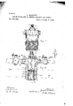
In the drawings Figure 1 shows a side elevation of my device and Fig.2 a vertical sec- ;tional view thereof withth'e regula'tioncocks mechanism. V iThe-numeral 1' shows the casing of my device; 2,: the gas intake opening; 3, the air intake opening; 4, a screw'plng attached to the vz;ilve' controlling and mi'xingthe gas and air, ifhich valveconsists of astem 5. having a regnlating'nut 7 and closing spring 6; the, stem being attached to a- .chan1bered valve 9 consisting of' a chamb i-having its upper end closed by an annular screw plug 8 in which the stem 5 is hel-d'and has openings 10 formed -slantingly'and'affiording'ingress to the chainher from the top edge thereof.
Thecasing'of the chamber qrvalve'flhas ;,t'w'o grooves 12 and-13. formed in its outer su r-. face'a'nd below the upper-groove is-a row of perforations 11 and near the bottom of the valve 9 1's another row of perforations 17, gm extreme bottomef the valve ending in a ange.j. ,The main casing 1'- has a central opening in which valve 'Brest's and one of its sides has an opening 15 either bored or cored out, which opening 15 is in-LcOinmuHication with v: the gasinlet2 and-"at its lower endit opens "-intolth'einteri'orforthe chamber in maincasing 1 but. said lower opening is' closed,
when valve 9 is in the chamber and closed. T
Valves Band 19 are preferably attached set in position therein is screwed nto an opening in,the cylinder of the gas engine soas to be in full and free communication with said interior. cylinder with the correct proportion of gas and air mixed, we'will suppose that a gas is Inorder to supplythe engine being used that requires in-the mixture one part of gas to seven parts of air. It will be necessary therefore, to so set the valves 18 audit! that while one" part of gas is entering through gas valve 18, seven parts of air will enter through air valve 19'Jand this is done bytur-ning the valves so that just this quantity ot gas and air will pass through themre v spectively in thesame space of .ti neand nil-- der' a given suctionmade by the down-.or
suction strokeof the engine'piston. -The' I valves 'beingsoset the arms 01:.handlSi2O i and 21 being slotted for that'pnrpose, are attached by the winged nuts 25 to a 1:06.22 whichforms a portion of alink lever device, the actuating link 23 being pivoted to the spindle of thegovernoi' preferably but it may be put in connection therewith in any otherdesired manner Doing so in connecftion with, the governor, every extra demand for power on the engine causes thegovernor to w so act asf'to pull 'onithe link 23 which moves the rod-22 opening th'e'vaives 18 and 19"in1'exa proportion admittingmore gas bntjalso ad tingmore air with it,but keepingithe adrni ture in ,the proportion of one toisev'e'n. Wjh' the loadis 'thrown'ofitho engine the governor acts to move .the'link in the opposite direction i so that the valves'fl 8 jand--19 are partly closed too but still keeping the proportion of air and gas supplied to the cylinder as one is to seven. 'By this arrangement there is provided a means whereby the proportion of gas and air be kept always constant and the proportions of the mixture may be in such quantities as may be determined on, as it a gas is being used that requiresa mixture of one of gas to ten of air the valves may he set to supply that mixture and the governor will control the valves .perfectly. The gas, as it enters chamber can not pass out of the same when the valve 9 is closed, 2'. e.,'raised"in the casing 1 to its highest point, by the spring 6, but the air 15 from valve 19 enters the chamber in valve 9 through openings 10. As the piston makes a down or suction stroke (reference is had in this specification only to a vertical gas engine having its cylinder at the top of the frame) valve 9 is drawn down or opened when perforations 11 register with opening 16 when the gas passes through perforations lland mineswith the air in the chamber and is also drawn-out of the same through openings 17 into the .engine cylinder well mixed and sprayed and is then ready for the compression stroke of the piston which stroke acts to close the valve 9 in conjunction with spring 6 and after compression, the mixed gas and air in the cylinder is exploded. I
The grooves 12,,13, and 14 are used as. in bricators or oil reservoirs wherebytthe 'valve 9 is enabled to operate easily, the oil-used as a lubricant resting in these against the sides of the valves.-
It will be noticed that the handles to the valves-19 and 18, said-handles being '20' and 21, are attached to the valve stem by set screws 26. In setting these valves so as to pass a certain quantity of gas or air, the set screw 26 is loosened and the handle set at such an angle as may be found adequate to grooves and leave the valve open to pass the desired quantityof gas or air, when the set screws 26 26, are set fast after which the handles- 20 and 21 are made movably fast to the rod 22 by the winged nuts 25, 25, after which the governor of the engine will operate the valves in accordance with'the load thrown on or off the engine.
The dotted lines 28 show the top or head of the engine cylinder. The feathered arrows show the courseot the gas and the plain arrows the course-of the air.
Having described my invention so that those skilled in the art may know how to make 7 and use the same, whait'l claim, and desire to secure by Letters Patent, is'- 1. A mixing and spraying device for oilor gas engines consisting of a casing having at-least two chambers and a tubular valve arranged to pnove in one of said chambers and open-and close an outlet port in the second, said valve partly filling the chamber it moves in, leaving I a gas or oil chamber as -15,'the tubular an open space in saidchamber and having inlet ports leading frornthe interior of the valve to the said open space, and having other inlpt ports constantly closed to the contents of said open space arranged so that when the valve, is opened said ports will register with the outlet port of the second chamber,'said valve having spraying ports arranged so that when thevalve is opened the-contents of both chambers after entering the valve will together besprayed. from the spraying ports into the engine cylinder and be'closed when the valve is closed and having means for opening and closing thevalve substantially as de scribed.
- 2. In a mixing and spraying device for gas or oil engines, a casing having an air charm ber. and a gas or oil chamber'and a tubular valve arranged to move in the air chamber and partly fill it leaving an open space in said chamber, said chamber being in commnnication with a supply of gas or oil, said valve having air ports leading from the air charnher into the valve and gas or oil ports leading from the gas or oil chamber into the valve, and having spraying ports, the air ports being constantly open and the gas or oil ports arranged to register with the outlet po'rtof the oil chamber when the valve is openand to be moved out of register therewith when the valve is closed, the spraying ports bein 'arranged to spray the air and oil or 'gajs rom' the tubular valve into the engine cylinder when the valve is open and to be closed when the valvecloses and having means for opening and closing the valve'substantially as detoe scribed.
3. In a device of the character described a casingas l-,having an air chamber con taining a tubular valve as -9- and having :05 valve being closed by a removable device as 8 and having a valve. stem and air inlet ports as -l0- and gas or oil inlet ports as 11 and spraying ports as l7- said valve being arranged to move in said chamber and arranged so that air will enter the valve through 'the ports as --10'- and when the valve is open gas or oil will enter said valve through ports as -11- and the gas or oil and airbe sprayed into the engine cylinder through spraying ports as 17- and when the valve is closed the intake gas or all ports JOSEPH nonison. Witnessesi J. F. HARRIS, W. M. Bsown.
Publications (1)
| Publication Number | Publication Date |
|---|---|
| US532099A true US532099A (en) | 1895-01-08 |
Family
ID=2600872
Family Applications (1)
| Application Number | Title | Priority Date | Filing Date |
|---|---|---|---|
| US532099D Expired - Lifetime US532099A (en) | Robison |
Country Status (1)
| Country | Link |
|---|---|
| US (1) | US532099A (en) |
Cited By (1)
| Publication number | Priority date | Publication date | Assignee | Title |
|---|---|---|---|---|
| US4553519A (en) * | 1982-09-27 | 1985-11-19 | Masson Laverne F | Propane feeding device for internal combustion engines |
-
0
- US US532099D patent/US532099A/en not_active Expired - Lifetime
Cited By (1)
| Publication number | Priority date | Publication date | Assignee | Title |
|---|---|---|---|---|
| US4553519A (en) * | 1982-09-27 | 1985-11-19 | Masson Laverne F | Propane feeding device for internal combustion engines |
Similar Documents
| Publication | Publication Date | Title |
|---|---|---|
| US532099A (en) | Robison | |
| US2084340A (en) | Carburetor for internal combustion engines | |
| US986754A (en) | Controlling device for internal-combustion engines. | |
| US746449A (en) | Carburetter for gas-engines. | |
| US8960154B2 (en) | Electronic fuel control system | |
| US741959A (en) | Vaporizer for hydrocarbon-engines. | |
| US761392A (en) | Carbureter for explosion-engines. | |
| US1249381A (en) | Carbureter. | |
| US1236267A (en) | Kerosene-carbureter. | |
| US806822A (en) | Carbureter. | |
| US967407A (en) | Carbureter for explosive-engines. | |
| US976258A (en) | Carbureter. | |
| US1354327A (en) | Carbureter | |
| US836764A (en) | Carbureter. | |
| US1459667A (en) | Association | |
| US556069A (en) | Clark sintz | |
| US1078816A (en) | Atomizing and mixing valve. | |
| US1293908A (en) | Carbureter. | |
| US726986A (en) | Carbureter for gas-engines. | |
| US776406A (en) | Vaporizer for hydrocarbon-engines. | |
| US1754972A (en) | Carburetor | |
| US1493567A (en) | Carburetor | |
| US1510028A (en) | Carburetor | |
| US1000451A (en) | Carbureter. | |
| US1196669A (en) | Carbureter. |