US532015A - Salt-trough - Google Patents
Salt-trough Download PDFInfo
- Publication number
- US532015A US532015A US532015DA US532015A US 532015 A US532015 A US 532015A US 532015D A US532015D A US 532015DA US 532015 A US532015 A US 532015A
- Authority
- US
- United States
- Prior art keywords
- trough
- salt
- box
- uprights
- sills
- Prior art date
- Legal status (The legal status is an assumption and is not a legal conclusion. Google has not performed a legal analysis and makes no representation as to the accuracy of the status listed.)
- Expired - Lifetime
Links
- 150000003839 salts Chemical class 0.000 description 5
- 210000005069 ears Anatomy 0.000 description 3
- 238000010276 construction Methods 0.000 description 1
Images
Classifications
-
- A—HUMAN NECESSITIES
- A01—AGRICULTURE; FORESTRY; ANIMAL HUSBANDRY; HUNTING; TRAPPING; FISHING
- A01K—ANIMAL HUSBANDRY; AVICULTURE; APICULTURE; PISCICULTURE; FISHING; REARING OR BREEDING ANIMALS, NOT OTHERWISE PROVIDED FOR; NEW BREEDS OF ANIMALS
- A01K5/00—Feeding devices for stock or game ; Feeding wagons; Feeding stacks
- A01K5/02—Automatic devices
- A01K5/025—Automatic devices with doors or lids activated by the animals to access feeding place or trough
Definitions
- This invention relates to salt troughs and has for its object to provide a device of the character set forth, which is so adjusted that the weight of the animal will cause it to tilt forward in the proper position to expose the contents, and when the weight is removed from the platform the box containing the salt or other material will be pulled back under cover in an upright position.
- Afurther object of the invention is to provide a cheap and economical salt trough which is noiseless in its operation and wherein the contents of the box or trough will be protected from the elements when not in use, and thereby prevent the several parts from getting out of working order.
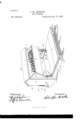
- the accompanying drawing represents a perspective view of a salt trough embodying the invention.
- the numeral 1 designates opposite side pieces or uprights having a rear upper cross strip 2 and a roof or cover 2".
- sills 3 Secured to the lower inner portions of the opposite side pieces or uprights l are sills 3 which project a greater distance toward the front than from the rear of the said side pieces or uprights, and extending from one sill to the other and bearing against the rear edges of the said pieces or uprights is a cross brace 3*.
- operating beams at which have their upper edges extending above the level of the upper edges of the said sills 3 and are pivoted to the latter adjacent Serls1No.482,183. (N0 model.)
- the rear portion of the box or trough is supplied with ears 10 to which the upper parts of springs 11 are connected, the lower ends of said springs being secured to the rear portions of the sills 3, and his intended that the said springs may be adjusted to or from the rear ends of the sills 3 to compensate for the variation of weight of the box or trough 5 in order to render the normal position of said box or trough closed or under the roof or cover 2*.
- the animal steps upon the platform 7 and depresses the beams 4, which drawing down upon the links 5 pull the trough or box outward in the position shown, against the retractile action of the springs 11, and thereby the contents of the said box or trough are exposed.
- the springs 11 come into play and'throw the box or trough backward under the cover or roof 2 thereby protecting the contents of the same.
Landscapes
- Life Sciences & Earth Sciences (AREA)
- Environmental Sciences (AREA)
- Birds (AREA)
- Animal Husbandry (AREA)
- Biodiversity & Conservation Biology (AREA)
- Housing For Livestock And Birds (AREA)
Description
(No Model.)
G. M. ARTHUR.
SALT TROUGH.
N0. 532,015. Patented Jan. 8, 1895.
UNITED STATES PATENT ()FFICE.
CHRISTOPHER M. ARTHUR, OF NEAR BETHANY, MISSOURI.
SALT-TROUGH.
SIEEGIFIOATION forming part of Letters Eatent No. 532,015, dated January 8, 1895.
Application filed August I, 1893.
T0 aZZ whom it may concern:
Be it known that I, CHRISTOPHER M. AR- THUR, a citizen of the United States, residing near Bethany, in the county of Harrison, State of Missouri, have invented certain new and useful Improvements in Salt-Troughs; and I do hereby declare the following to be a full, clear, and exact description of the invention, such as will enable others skilled in the art to which it pertains to make and use the same.
This invention relates to salt troughs and has for its object to provide a device of the character set forth, which is so adjusted that the weight of the animal will cause it to tilt forward in the proper position to expose the contents, and when the weight is removed from the platform the box containing the salt or other material will be pulled back under cover in an upright position.
Afurther object of the invention is to provide a cheap and economical salt trough which is noiseless in its operation and wherein the contents of the box or trough will be protected from the elements when not in use, and thereby prevent the several parts from getting out of working order.
With these and other objects in view the invention consists of the construction and arrangement of the several parts, which will be more fully hereinafter described and claimed.
The accompanying drawing represents a perspective view of a salt trough embodying the invention.
In the drawing the numeral 1 designates opposite side pieces or uprights having a rear upper cross strip 2 and a roof or cover 2". Secured to the lower inner portions of the opposite side pieces or uprights l are sills 3 which project a greater distance toward the front than from the rear of the said side pieces or uprights, and extending from one sill to the other and bearing against the rear edges of the said pieces or uprights is a cross brace 3*. Along the inner opposing sides of the sills 3 are mounted operating beams at which have their upper edges extending above the level of the upper edges of the said sills 3 and are pivoted to the latter adjacent Serls1No.482,183. (N0 model.)
to their front ends by bolts 4*, the rear ends of said operating beams being free to have movement on the said bolts 4 which serve as fulcrums. On the operating beams at is secured a platform 7 upon which the animal stands in feeding from the trough. The rear upper portions of the operating beams are supplied with staples 4 to which are pivotally attached links 5 Between the opposite side pieces or uprights 1 is pivotally mounted a trough or feeding box 5 having the opposite side pieces 8 depending below the bottom of the same and pivotally attached to said side pieces or uprights by bolts 6. To the front edges of the said depending portions of the side pieces 8 are attached staples 9 to which the upper portions of the links 5 are pivotally secured. The rear portion of the box or trough is supplied with ears 10 to which the upper parts of springs 11 are connected, the lower ends of said springs being secured to the rear portions of the sills 3, and his intended that the said springs may be adjusted to or from the rear ends of the sills 3 to compensate for the variation of weight of the box or trough 5 in order to render the normal position of said box or trough closed or under the roof or cover 2*.
In operation, the animal steps upon the platform 7 and depresses the beams 4, which drawing down upon the links 5 pull the trough or box outward in the position shown, against the retractile action of the springs 11, and thereby the contents of the said box or trough are exposed. When the animal moves from the platform 7, the springs 11 come into play and'throw the box or trough backward under the cover or roof 2 thereby protecting the contents of the same.
It will be understood that either salt or food may be placed in the box or trough with the same advantage and operation.
Having thus described the invention, what is claimed as new is- In a device of the character set forth, the combination of uprights supporting a cover or roof, lower sills to which said uprights are secured, a box or trough pivotally mounted between the said uprights and adapted to move under the said cover and having ears trough or box and to said projecting ears, subprojecting rearwardly therefrom, operating stantially as and for the purposes specified. beams pivotaily connected to the said sills, 1 a platform on the operating beams, links ,OHRISI OPHER ARTHUR 5 connected to the rear of the operating beams Witnesses:
and the lower front portion of thetrough or WM. SMITH, I box, and springs attached to the rear of the E. M. ASHFORD.
Publications (1)
| Publication Number | Publication Date |
|---|---|
| US532015A true US532015A (en) | 1895-01-08 |
Family
ID=2600788
Family Applications (1)
| Application Number | Title | Priority Date | Filing Date |
|---|---|---|---|
| US532015D Expired - Lifetime US532015A (en) | Salt-trough |
Country Status (1)
| Country | Link |
|---|---|
| US (1) | US532015A (en) |
-
0
- US US532015D patent/US532015A/en not_active Expired - Lifetime
Similar Documents
| Publication | Publication Date | Title |
|---|---|---|
| US532015A (en) | Salt-trough | |
| US420168A (en) | Feed-trough | |
| US462146A (en) | Feed-trough | |
| US992657A (en) | Tram-car fender. | |
| US553208A (en) | And charles f | |
| US204482A (en) | Improvement in foot-baths for horses | |
| US2709635A (en) | Storage cabinet | |
| US1080436A (en) | Poultry-feeding device. | |
| US1077098A (en) | Mouse or rat trap. | |
| US1083980A (en) | Hen's nest. | |
| US712967A (en) | Stanchion. | |
| US541268A (en) | Car-fender | |
| US399258A (en) | Feed-trough | |
| US892071A (en) | Feeding-trough. | |
| US543762A (en) | Device for starting race-horses | |
| US599763A (en) | Stable | |
| US356086A (en) | Stanchion | |
| US251586A (en) | Deicks | |
| US419296A (en) | Stanchion | |
| US1053853A (en) | Car-fender. | |
| US247917A (en) | Portable stable | |
| US1105084A (en) | Harvester attachment. | |
| US583017A (en) | Car-fender | |
| US682771A (en) | Fender for vehicles. | |
| US580892A (en) | Flood-gate |