US531663A - Base for incandescent electric lamps - Google Patents
Base for incandescent electric lamps Download PDFInfo
- Publication number
- US531663A US531663A US531663DA US531663A US 531663 A US531663 A US 531663A US 531663D A US531663D A US 531663DA US 531663 A US531663 A US 531663A
- Authority
- US
- United States
- Prior art keywords
- electric lamps
- base
- incandescent electric
- disk
- shell
- Prior art date
- Legal status (The legal status is an assumption and is not a legal conclusion. Google has not performed a legal analysis and makes no representation as to the accuracy of the status listed.)
- Expired - Lifetime
Links
- 239000011810 insulating material Substances 0.000 description 3
- 239000000126 substance Substances 0.000 description 3
- 238000010276 construction Methods 0.000 description 2
- 238000012937 correction Methods 0.000 description 2
- OKTJSMMVPCPJKN-UHFFFAOYSA-N Carbon Chemical compound [C] OKTJSMMVPCPJKN-UHFFFAOYSA-N 0.000 description 1
- 229920000049 Carbon (fiber) Polymers 0.000 description 1
- 240000001973 Ficus microcarpa Species 0.000 description 1
- 239000011324 bead Substances 0.000 description 1
- 229910052799 carbon Inorganic materials 0.000 description 1
- 239000004917 carbon fiber Substances 0.000 description 1
- 238000004519 manufacturing process Methods 0.000 description 1
- 239000000463 material Substances 0.000 description 1
- 239000002184 metal Substances 0.000 description 1
- VNWKTOKETHGBQD-UHFFFAOYSA-N methane Chemical compound C VNWKTOKETHGBQD-UHFFFAOYSA-N 0.000 description 1
- 238000000926 separation method Methods 0.000 description 1
Images
Classifications
-
- H—ELECTRICITY
- H01—ELECTRIC ELEMENTS
- H01R—ELECTRICALLY-CONDUCTIVE CONNECTIONS; STRUCTURAL ASSOCIATIONS OF A PLURALITY OF MUTUALLY-INSULATED ELECTRICAL CONNECTING ELEMENTS; COUPLING DEVICES; CURRENT COLLECTORS
- H01R4/00—Electrically-conductive connections between two or more conductive members in direct contact, i.e. touching one another; Means for effecting or maintaining such contact; Electrically-conductive connections having two or more spaced connecting locations for conductors and using contact members penetrating insulation
- H01R4/28—Clamped connections, spring connections
- H01R4/30—Clamped connections, spring connections utilising a screw or nut clamping member
- H01R4/34—Conductive members located under head of screw
Definitions
- My invention relates to the manufacture Of bases vfor incandescent electric lamps, whereby they are improved in construction and operation.
- the object of my invention is to improve the base by using a vitreous intusible substance for the insulating part, and to improve the details of construction.
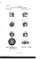
- Figure l is a side view of a base for an incandescent electric lamp.
- Fig. 2 is a top view.
- Fig. 3/ is a vertical central section On line l l.
- Fig. e is a vertical' central section on line 2 2.
- Fig. 5 is a bottom view.
- Fig. 6 is a sectional view of the shell with the vitreous disk in place.
- Fig. 7 is an enlarged top view of insulating-disk and central contact piece.
- Fig. 8 is an enlarged sectional View on line 3 3 of Fig. 7.
- A is a disk of vitreous insulating material to which are attached the contact pieces B and O.
- f D is a metal shell which supports the disk A.
- the contact piece B is made of some electrical conducting substance and is attached to A by means of the prongs b b forming part of B and bent so as to pass through the openings a, c, holding it firmlyin position by pressing against the inclined sides of said openings c a.
- One terminal of the carbon ber of the lamp consisting of a wire can be passed through either aperture a or a and soldered to B.
- The' contact piece O is .made of some electrical conducting substance and occupies an opening a in A. It is attached to A concentrically by means of anges c' c2 which embrace the top and bottom respectively of A and prevent their separation.
- the contact piece C has a recess in its surface for the purpose of receiving the wire, constituting one terminai of the carbon fiber of the lamp, which is soldered thereto.
- This recess may consist of agroove c4 near the edge or the edge maybe beveled as at c5, or theins ulating material may be recessed.
- the wire terminal may pass through-either groove a2.
- two points c3 c3 of the flange c2 enter respectively two notches a3 asin A.
- the sides of opening a have the grooves a2 a2 extending from top to bottom of A.
- I provide the shell with an inwardly extended annular camshaped head d, and the inner surface of the disk is beveled off at opposite sides, thus Varying the thickness of the edge, or, ⁇ in other words, providing an undulating annular surface conforming to and designed to bear upon the head d.
- a base for an incandescent lamp the combination of a shell having an inwardly extended cam-shaped head, and a disk of -insulating material having its edge surface col1- formed substantially to said head, substang tially as specified.
- vitreous disk having its edge of varying thickness, substantially as specified.
Landscapes
- Fastening Of Light Sources Or Lamp Holders (AREA)
Description
(.No Model) G. C. THOMAS. BASE Fon INCANDBSGBNT ELECTRIC LAMPS. No. 531,663.
Patented Jan'. -1, 1895 .uilllilliill o.. wAsm.
UNITED STATES PATENT OFFICE. e
GEORGEO. THOMAS, OF SOUTH FRAMINGHAM, MASSACHUSETTS.
BASEI FORiNCAN DESCENT ELECTRIC LAMPS.
v SPECIFICATION forming part of Letters Patent No. 531,663, dated January 1, 1 895.
Application tiled November 28, 1893. Serial No. 492,316. (No model.)
To a/ZZ whom it may concern:
Be it known that I, GEORGE O. THOMAS, a citizen of the United States, and a resident of South Framingham, in the county of Middlesex and State of Massachusetts, have invented certain newand useful Improvements in Bases for Incandescent Electric Lamps, of which the following is a specification.
My invention relates to the manufacture Of bases vfor incandescent electric lamps, whereby they are improved in construction and operation.
The object of my invention is to improve the base by using a vitreous intusible substance for the insulating part, and to improve the details of construction.
My invention consists in the improvements designated and combinations specifically claimed. v Y
Figure l is a side view of a base for an incandescent electric lamp. Fig. 2 is a top view. Fig. 3/is a vertical central section On line l l. Fig. eis a vertical' central section on line 2 2. Fig. 5 is a bottom view. Fig. 6 is a sectional view of the shell with the vitreous disk in place. Fig. 7 is an enlarged top view of insulating-disk and central contact piece. Fig. 8 is an enlarged sectional View on line 3 3 of Fig. 7.
A is a disk of vitreous insulating material to which are attached the contact pieces B and O.
f D is a metal shell which supports the disk A.
The contact piece B is made of some electrical conducting substance and is attached to A by means of the prongs b b forming part of B and bent so as to pass through the openings a, c, holding it firmlyin position by pressing against the inclined sides of said openings c a. One terminal of the carbon ber of the lamp consisting of a wire can be passed through either aperture a or a and soldered to B. The' contact piece O is .made of some electrical conducting substance and occupies an opening a in A. It is attached to A concentrically by means of anges c' c2 which embrace the top and bottom respectively of A and prevent their separation. The contact piece C has a recess in its surface for the purpose of receiving the wire, constituting one terminai of the carbon fiber of the lamp, which is soldered thereto. This recess may consist of agroove c4 near the edge or the edge maybe beveled as at c5, or theins ulating material may be recessed. The wire terminal may pass through-either groove a2. Y
To prevent the turning of O in A, two points c3 c3 of the flange c2 enter respectively two notches a3 asin A. The sides of opening a have the grooves a2 a2 extending from top to bottom of A. n,
To prevent a rotary movement of the disk A, with relation to the shell D, I provide the shell with an inwardly extended annular camshaped head d, and the inner surface of the disk is beveled off at opposite sides, thus Varying the thickness of the edge, or,`in other words, providing an undulating annular surface conforming to and designed to bear upon the head d.
1. In a base for an incandescent lamp, the combination of a shell having an inwardly extended cam-shaped head, and a disk of -insulating material having its edge surface col1- formed substantially to said head, substang tially as specified.
2. The combination of a shell having an inv wardly extended annular, cam shaped head, and a disk of insulating material having an undulating inner edge, substantially as specitied.
3. In bases for incandescent electric lamps, a vitreous disk having its edge of varying thickness, substantially as specified.
Signed at South Framingham, in the county of Middlesex and State of Massachusetts, this 24th day ol" November, A. D. 1893.
GEO. o. THOMAS.
M Qorrections in ,Letters ,Patent No. 531,663.`
It; is certified that in Letters Patent No. 531,663, granted January l, 1895, upon the application of' George C. Thomas,.of South Framingham, Massachusetts, for an improvement in Bases for Incandescent Electric Lamps, errors appear in theprinted specification requiring correction as follows: In lines 66, 7l, 75, 77, and 80, the Word head 7 should read bead; and that thesaid Letters Patent should be read with these corrections therein that the same may conform to the recordxof the case in the Patent O'ce. Y n l Signed, countersigned, and sealed this 29th day of January, A. D. 18955 f f Assistant S'emetm'y of the Interior. Countersigned JOHN S. SEYMOUR,
Commz'ssioher of Patents.
Publications (1)
| Publication Number | Publication Date |
|---|---|
| US531663A true US531663A (en) | 1895-01-01 |
Family
ID=2600437
Family Applications (1)
| Application Number | Title | Priority Date | Filing Date |
|---|---|---|---|
| US531663D Expired - Lifetime US531663A (en) | Base for incandescent electric lamps |
Country Status (1)
| Country | Link |
|---|---|
| US (1) | US531663A (en) |
-
0
- US US531663D patent/US531663A/en not_active Expired - Lifetime
Similar Documents
| Publication | Publication Date | Title |
|---|---|---|
| US1732707A (en) | winsboro | |
| US531663A (en) | Base for incandescent electric lamps | |
| US3251023A (en) | Directly attachable light socket | |
| US2758198A (en) | Flower-like light reflector for lamps and lighting fixtures | |
| US2992323A (en) | Electric light fixture | |
| US1560289A (en) | Miniature lamp | |
| US1368239A (en) | Electric-lamp hanger | |
| US796922A (en) | Electric-light fixture. | |
| US1046431A (en) | Electric-lamp socket. | |
| US473240A (en) | Lamp-shade and holder for incandescent lamps | |
| US1335644A (en) | Bernarb bebtedict | |
| US1771002A (en) | Bulb holder for flash lights | |
| US3372363A (en) | Light bulb construction | |
| US549201A (en) | Charles j | |
| US1417481A (en) | Shade holder | |
| US497849A (en) | The nobrib peters co | |
| US659061A (en) | Electric lamp. | |
| US1235632A (en) | Upright shade-holder. | |
| US889812A (en) | Multiple socket for electric lamps. | |
| US902960A (en) | Electric-light fixture. | |
| US1025238A (en) | Weatherproof electric-lamp socket. | |
| US911475A (en) | Multiple lamp-socket. | |
| US973876A (en) | Shade-holder. | |
| US443562A (en) | Sigmund bergmans | |
| US979793A (en) | Shade-holder. |