US5312499A - Method and apparatus for making a loose tube fiber optic cable component - Google Patents
Method and apparatus for making a loose tube fiber optic cable component Download PDFInfo
- Publication number
- US5312499A US5312499A US07/963,173 US96317392A US5312499A US 5312499 A US5312499 A US 5312499A US 96317392 A US96317392 A US 96317392A US 5312499 A US5312499 A US 5312499A
- Authority
- US
- United States
- Prior art keywords
- grease
- passageway
- tube
- optical fibers
- chamber
- Prior art date
- Legal status (The legal status is an assumption and is not a legal conclusion. Google has not performed a legal analysis and makes no representation as to the accuracy of the status listed.)
- Expired - Fee Related
Links
Images


Classifications
-
- G—PHYSICS
- G02—OPTICS
- G02B—OPTICAL ELEMENTS, SYSTEMS OR APPARATUS
- G02B6/00—Light guides; Structural details of arrangements comprising light guides and other optical elements, e.g. couplings
- G02B6/44—Mechanical structures for providing tensile strength and external protection for fibres, e.g. optical transmission cables
- G02B6/4479—Manufacturing methods of optical cables
- G02B6/4483—Injection or filling devices
-
- B—PERFORMING OPERATIONS; TRANSPORTING
- B29—WORKING OF PLASTICS; WORKING OF SUBSTANCES IN A PLASTIC STATE IN GENERAL
- B29C—SHAPING OR JOINING OF PLASTICS; SHAPING OF MATERIAL IN A PLASTIC STATE, NOT OTHERWISE PROVIDED FOR; AFTER-TREATMENT OF THE SHAPED PRODUCTS, e.g. REPAIRING
- B29C48/00—Extrusion moulding, i.e. expressing the moulding material through a die or nozzle which imparts the desired form; Apparatus therefor
- B29C48/03—Extrusion moulding, i.e. expressing the moulding material through a die or nozzle which imparts the desired form; Apparatus therefor characterised by the shape of the extruded material at extrusion
- B29C48/05—Filamentary, e.g. strands
-
- B—PERFORMING OPERATIONS; TRANSPORTING
- B29—WORKING OF PLASTICS; WORKING OF SUBSTANCES IN A PLASTIC STATE IN GENERAL
- B29C—SHAPING OR JOINING OF PLASTICS; SHAPING OF MATERIAL IN A PLASTIC STATE, NOT OTHERWISE PROVIDED FOR; AFTER-TREATMENT OF THE SHAPED PRODUCTS, e.g. REPAIRING
- B29C48/00—Extrusion moulding, i.e. expressing the moulding material through a die or nozzle which imparts the desired form; Apparatus therefor
- B29C48/03—Extrusion moulding, i.e. expressing the moulding material through a die or nozzle which imparts the desired form; Apparatus therefor characterised by the shape of the extruded material at extrusion
- B29C48/06—Rod-shaped
-
- B—PERFORMING OPERATIONS; TRANSPORTING
- B29—WORKING OF PLASTICS; WORKING OF SUBSTANCES IN A PLASTIC STATE IN GENERAL
- B29C—SHAPING OR JOINING OF PLASTICS; SHAPING OF MATERIAL IN A PLASTIC STATE, NOT OTHERWISE PROVIDED FOR; AFTER-TREATMENT OF THE SHAPED PRODUCTS, e.g. REPAIRING
- B29C48/00—Extrusion moulding, i.e. expressing the moulding material through a die or nozzle which imparts the desired form; Apparatus therefor
- B29C48/03—Extrusion moulding, i.e. expressing the moulding material through a die or nozzle which imparts the desired form; Apparatus therefor characterised by the shape of the extruded material at extrusion
- B29C48/09—Articles with cross-sections having partially or fully enclosed cavities, e.g. pipes or channels
-
- B—PERFORMING OPERATIONS; TRANSPORTING
- B29—WORKING OF PLASTICS; WORKING OF SUBSTANCES IN A PLASTIC STATE IN GENERAL
- B29C—SHAPING OR JOINING OF PLASTICS; SHAPING OF MATERIAL IN A PLASTIC STATE, NOT OTHERWISE PROVIDED FOR; AFTER-TREATMENT OF THE SHAPED PRODUCTS, e.g. REPAIRING
- B29C48/00—Extrusion moulding, i.e. expressing the moulding material through a die or nozzle which imparts the desired form; Apparatus therefor
- B29C48/15—Extrusion moulding, i.e. expressing the moulding material through a die or nozzle which imparts the desired form; Apparatus therefor incorporating preformed parts or layers, e.g. extrusion moulding around inserts
- B29C48/156—Coating two or more articles simultaneously
-
- B—PERFORMING OPERATIONS; TRANSPORTING
- B29—WORKING OF PLASTICS; WORKING OF SUBSTANCES IN A PLASTIC STATE IN GENERAL
- B29C—SHAPING OR JOINING OF PLASTICS; SHAPING OF MATERIAL IN A PLASTIC STATE, NOT OTHERWISE PROVIDED FOR; AFTER-TREATMENT OF THE SHAPED PRODUCTS, e.g. REPAIRING
- B29C48/00—Extrusion moulding, i.e. expressing the moulding material through a die or nozzle which imparts the desired form; Apparatus therefor
- B29C48/25—Component parts, details or accessories; Auxiliary operations
- B29C48/30—Extrusion nozzles or dies
- B29C48/32—Extrusion nozzles or dies with annular openings, e.g. for forming tubular articles
- B29C48/34—Cross-head annular extrusion nozzles, i.e. for simultaneously receiving moulding material and the preform to be coated
-
- B—PERFORMING OPERATIONS; TRANSPORTING
- B29—WORKING OF PLASTICS; WORKING OF SUBSTANCES IN A PLASTIC STATE IN GENERAL
- B29C—SHAPING OR JOINING OF PLASTICS; SHAPING OF MATERIAL IN A PLASTIC STATE, NOT OTHERWISE PROVIDED FOR; AFTER-TREATMENT OF THE SHAPED PRODUCTS, e.g. REPAIRING
- B29C48/00—Extrusion moulding, i.e. expressing the moulding material through a die or nozzle which imparts the desired form; Apparatus therefor
- B29C48/03—Extrusion moulding, i.e. expressing the moulding material through a die or nozzle which imparts the desired form; Apparatus therefor characterised by the shape of the extruded material at extrusion
- B29C48/07—Flat, e.g. panels
- B29C48/08—Flat, e.g. panels flexible, e.g. films
-
- B—PERFORMING OPERATIONS; TRANSPORTING
- B29—WORKING OF PLASTICS; WORKING OF SUBSTANCES IN A PLASTIC STATE IN GENERAL
- B29L—INDEXING SCHEME ASSOCIATED WITH SUBCLASS B29C, RELATING TO PARTICULAR ARTICLES
- B29L2011/00—Optical elements, e.g. lenses, prisms
- B29L2011/0075—Light guides, optical cables
Definitions
- the invention deals with method and apparatus for making a loose tube buffered fiber optic cable component.
- Fiber optic cables usually come in either the loose tube or tight buffered variety and their chief component is made by horizontal or vertically disposed apparatus.
- This invention concerns a horizontally disposed improved apparatus and method of making a loose tube cable component, which comprises a grease or hydrocarbon jelly like substance coated optical fibers loosely disposed inside of a tube made from some kind of suitable polymer, such as polycarbonate.
- the grease or jelly coated fibers are so disposed so that they may move relative to one another and to the tube itself.
- the prior art teaches one to assemble one or more optical fibers or a bundle of optical fiber ribbons in an elongated stream, a petroleum grease or jelly is applied thereto and then a plastic tube is extruded over the previously coated fibers.
- Such components are assembled into a core over which a plastic jacket is formed to complete a cable assembly. See, for example, U.S. Pat. No. 4,828,352, the contents of which are herein incorporated by reference.
- Horizontally disposed prior art loose tube component making apparatus employ a long needle that extends from a grease injection head (where optical fibers, or ribbons, are coated with a jelly like hydrocarbon and then introduced into the needle) and a polymer extrusion crosshead, which forms a plastic tube about the coated fibers as they exit the polymer crosshead.
- a grease injection head where optical fibers, or ribbons, are coated with a jelly like hydrocarbon and then introduced into the needle
- a polymer extrusion crosshead which forms a plastic tube about the coated fibers as they exit the polymer crosshead.
- Such apparatus requires that the needle have a centering device to manually center the needle in the X-Y position. Satisfactory results can be achieved using this type of apparatus if the polymer crosshead has a plastic flow passageway that is less than six (6) inches. Unsatisfactory results have been observed with crossheads having a plastic flow passage in the neighborhood of 12 inches or more.
- the present invention has as its objectives three things: (1) decreased tension on the fiber, short needles can be used; (2) prior art X-Y positioning apparatus is eliminated, the disclosed apparatus is self centering; and, (3) elimination of a tendency to waste jelly or grease like hydrocarbon fill material experienced in prior art apparatus arising out of grease back flow and/or prewetting.
- the disclosed invention is a method and apparatus for making a loose tube fiber optic cable component, namely a polymer plastic tube in which there is a disposed one or more optical fibers coated with a suitable grease or petroleum jelly in such a manner that the fibers are moveable relative one to another and/or with the tube itself.
- the method includes the steps of (a) providing a plastic extrusion crosshead and a grease injection unit, such a combination having first, second, and third concentric passageways and a chamber in communication with said first and second passageways; (b) moving one or more optical fibers (either in ribbon form or otherwise) along the first passageway into and out of the chamber; (c) flowing a mass of jelly like hydrocarbon filling compound (sometimes herein referred to as grease) through the second passageway into the chamber and into contact with the optical fibers in order to coat them; and, (d) flowing a mass of polymer resin through the third passageway and a die to form a polymer tube around the coated optical fibers after they exit the chamber.
- the optical fibers come into contact with the jelly like hydrocarbon in the chamber at a point only after the grease (and optical fibers as well) have traversed a majority of the length of the grease injection unit, applying the grease to the fibers at the last practical moment.
- Apparatus suitable for carrying out the invention includes two basic elements, a crosshead and a grease injection unit disposed in the crosshead.
- This combination has four passageways, two in the crosshead and two in the grease injection unit.
- the crosshead itself contains an entrance and exit port (a tube forming die).
- This passageway (a) connects the entrance with the exit port and is the path over which molten plastic (polymer) is forced to flow in a conventional prior art manner; and, (b) circumscribes a second passageway.
- Disposed in the second passageway in the crosshead is the grease injection unit, which has a length such that it traverses a major portion of the distance between the entrance and exit ports of the crosshead.
- first, second and third tubular members concentrically disposed, one to another.
- the first and second tubes are spaced apart from one another in such a manner that they form a travel path (fourth passageway) therebetween through which the grease like hydrocarbon is forced to flow in a manner well known to the prior art.
- the first tube (circumscribed by the second tube) itself delimits a third passageway through which yet to be grease coated optical fibers are traversed.
- the third and outer tube member circumscribes both the first and second tube and at a terminal end portion thereof forms a chamber in which there is a terminal portion of the first tube.
- the chamber itself is in communication with the third passageway thus allowing grease like resin to flow into the chamber and come into contact with the optical fibers as they pass through but only after the grease and fibers have traversed a majority of the length of the grease injection unit.
- Still another tube is employed (in the fiber optic trade this tube is called a needle) and is usually attached to the third tube.
- a needle Through this needle, grease coated fibers are passed and as they exit from the needle there is formed thereover a plastic tube by the exit port (die) of the crosshead. A terminal portion of the needle usually protrudes slightly beyond the crosshead.
- FIG. 1 is a cross sectional view of a loose tube fiber optic cable component.
- FIG. 2 is a schematic representation of prior art horizontal extrusion and grease injection apparatus used to manufacture the loose tube component of FIG. 1.
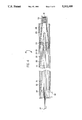
- FIG. 3 is a schematic cross sectional view of the apparatus of the present invention.
- FIG. 4 is a cross sectional view of the grease injection unit of FIG. 3.
- FIG. 5 is a cross sectional view of a needle used with the apparatus of FIG. 4.
- Plastic tube 2 is made from any suitable polymer, such as polycarbonate, formed about grease coated optical fibers 3-4.
- Optical fibers 4 can be either single fibers and/or optical fiber ribbons like that shown in U.S. Pat. No. 4,900,126, the contents of which are herein incorporated by reference.
- Plastic tube 2 can be either a single wall type or a multiwall type (not shown). For example it may be composed of two walls, both walls being formed from thermoplastic materials.
- Loose tube element 1 is made using the prior art apparatus shown as element 5 in FIG. 2.
- Such apparatus includes a grease injection unit 9 and a plastic extrusion crosshead 13.
- Grease injection unit 9 also contains a small diameter tube (or a needle) 10 that extends all the way through crosshead 13 to the other side where, at its terminal free surface, a plastic tube 2 is formed over grease coated optical fibers 3-4.
- Crosshead 13 has inlet port 6 and exit port (die) 8. Between these two ports there is passageway 7 (flow channel) through which there is flowed a suitable polymer in a manner well known to the prior art, e.g, extrusion.
- element 11 inside of grease injection device 9
- fibers 4 come into contact with the grease and stay in such contact all the way through the needle 10 until plastic tube is formed over the grease coated fibers 3-4.
- the invention is shown as element 12 in FIG. 3. Comparing the structures of FIGS. 2 and 3, the contact point 17 of the invention, where optical fibers 4 first contact grease, is further to the right than contact point 11 of FIG. 2 and the needle of FIG. 3 is much shorter than the needle 10 of FIG. 2. As mentioned above, additional apparatus is needed to manually center the needle in the X-Y axis. Such is not needed within the invention of FIG. 3.
- Element 15 is a crosshead, having a length longer than the length of crosshead 13 of FIG. 2. It has an inlet port 6 and a flow channel or passageway 7 and an exit port or die 8 much like that of FIG. 2.
- Crosshead 15 has another passageway shown by element 16, in which there is disposed grease injection unit 14, the details of which are more clearly shown in FIG. 4.
- crosshead 15 has an exit die 8 at which point molten polymer exits the crosshead to form polymer tube 2.
- Optical fibers 4 are traversed through tube 26 (more fully explained below in the description of FIG.
- Flow passageway 7 connects inlet port 6 and exit port (die) 8 and is spaced apart from and circumscribes chamber 16, in which grease injection unit 14 is snugly fitted. Needle 18 is attached to the grease injection unit in a manner discussed below, and protrudes beyond the terminal free surface of crosshead 15, at which point a polymer tube is formed around grease coated fibers shown by elements 3 and 4.
- FIG. 4 describing the details of grease injection unit 14, which fits into passageway 16 of crosshead 15.
- Crosshead 15 has first and second passageways 7 and 16 respectively.
- Grease injection unit 14 is composed of a plurality of concentrically disposed tubes, the important ones being 23, 24, 25 and 26, delimiting third and fourth passageways, 33 and 31 respectively.
- Non grease coated optical fibers enter tube 26 at 27, are traversed through passageway 33 and exit into chamber 28 at point 29, a terminal tube end portion of tube 26.
- Chamber 28 is delimited by a terminal portion of outer tube member 23 and is so disposed, that the non grease coated fibers remain uncoated until they have traveled a majority of the length, of grease injection unit 14.
- a suitable hydrocarbon grease is pumped into entrance 30, through passageway 34 into a third passageway 31, delimited by circumferentially disposed tubes 24 and 25, through passageway 35 and thus into chamber 28, where it first comes in contact with fibers 4 and it is here fibers 4 are grease coated. See elements 3-4.
- Grease coated fibers 3-4 pass through end member 22 then through needle 18, which is attached to member 22 by means of threaded portions 20 and 21 of elements 22 and 18 respectively. Thereafter, plastic tube 2 is formed over greased coated fibers 3 and 4 as shown by element 2 of FIG. 3.
- the invention applies a grease coating to a bundle of optical fibers or ribbons at the last practical moment, just before a plastic polymer tube is formed thereover.
Landscapes
- Engineering & Computer Science (AREA)
- Mechanical Engineering (AREA)
- Manufacturing & Machinery (AREA)
- Physics & Mathematics (AREA)
- General Physics & Mathematics (AREA)
- Optics & Photonics (AREA)
- Extrusion Moulding Of Plastics Or The Like (AREA)
Abstract
Description
Claims (6)
Priority Applications (1)
| Application Number | Priority Date | Filing Date | Title |
|---|---|---|---|
| US07/963,173 US5312499A (en) | 1992-10-19 | 1992-10-19 | Method and apparatus for making a loose tube fiber optic cable component |
Applications Claiming Priority (1)
| Application Number | Priority Date | Filing Date | Title |
|---|---|---|---|
| US07/963,173 US5312499A (en) | 1992-10-19 | 1992-10-19 | Method and apparatus for making a loose tube fiber optic cable component |
Publications (1)
| Publication Number | Publication Date |
|---|---|
| US5312499A true US5312499A (en) | 1994-05-17 |
Family
ID=25506845
Family Applications (1)
| Application Number | Title | Priority Date | Filing Date |
|---|---|---|---|
| US07/963,173 Expired - Fee Related US5312499A (en) | 1992-10-19 | 1992-10-19 | Method and apparatus for making a loose tube fiber optic cable component |
Country Status (1)
| Country | Link |
|---|---|
| US (1) | US5312499A (en) |
Cited By (12)
| Publication number | Priority date | Publication date | Assignee | Title |
|---|---|---|---|---|
| US6167180A (en) * | 1997-09-12 | 2000-12-26 | Alcatel | Cable having at least one layer of flexible strength members with adhesive and non-adhesive yarns for coupling an outer protective jacket and a buffer tube containing optical fibers |
| US6454251B1 (en) * | 2000-05-01 | 2002-09-24 | John C. Fish | Composite cord assembly |
| JP2009116240A (en) * | 2007-11-09 | 2009-05-28 | Fujikura Ltd | Extrusion method of loose tube and its device, and loose tube obtained by the extrusion method |
| WO2010019273A1 (en) * | 2008-08-15 | 2010-02-18 | Corning Cable Systems Llc | Optical fiber assemblies, and methods and apparatus for the manufacture thereof |
| US20110188821A1 (en) * | 2008-07-31 | 2011-08-04 | Bringuier Anne G | Optical Fiber Assemblies Having a Powder or Powder Blend at Least Partially Mechanically Attached |
| CN104133277A (en) * | 2014-07-16 | 2014-11-05 | 江苏通鼎光电股份有限公司 | Optical cable coating loose casing coating-type oil filling method |
| CN105666835A (en) * | 2016-01-14 | 2016-06-15 | 南京华信藤仓光通信有限公司 | Dry optical fiber ribbon loose tube air blowing molding device |
| AU2015203504B2 (en) * | 2008-08-15 | 2016-10-27 | Corning Optical Communications LLC | Optical fiber assemblies, and methods and apparatus for the manufacture thereof |
| CN108072947A (en) * | 2017-12-29 | 2018-05-25 | 通鼎互联信息股份有限公司 | A kind of mold for making multifiber cable |
| WO2021132376A1 (en) * | 2019-12-27 | 2021-07-01 | 昭和電線ケーブルシステム株式会社 | Loose tube-type optical cable production device and production method |
| CN115685466A (en) * | 2022-11-14 | 2023-02-03 | 长飞光纤光缆股份有限公司 | Central beam tube air-blowing micro cable, extrusion die and preparation method |
| CN118380207A (en) * | 2024-02-04 | 2024-07-23 | 江苏亨通电力智网科技有限公司 | High-strength weather-resistant insulating optical unit preparation process, device, optical unit and composite cable |
Citations (3)
| Publication number | Priority date | Publication date | Assignee | Title |
|---|---|---|---|---|
| US4372792A (en) * | 1981-10-15 | 1983-02-08 | Bicc Limited | Manufacture of a flexible stranded optical fiber body |
| US4474638A (en) * | 1982-02-26 | 1984-10-02 | Siemens Aktiengesellschaft | Device for manufacturing electrical and optical cables |
| US4810429A (en) * | 1986-07-31 | 1989-03-07 | Siemens Aktiengesellschaft | Method and apparatus for the manufacture of filled optical transmission elements |
-
1992
- 1992-10-19 US US07/963,173 patent/US5312499A/en not_active Expired - Fee Related
Patent Citations (3)
| Publication number | Priority date | Publication date | Assignee | Title |
|---|---|---|---|---|
| US4372792A (en) * | 1981-10-15 | 1983-02-08 | Bicc Limited | Manufacture of a flexible stranded optical fiber body |
| US4474638A (en) * | 1982-02-26 | 1984-10-02 | Siemens Aktiengesellschaft | Device for manufacturing electrical and optical cables |
| US4810429A (en) * | 1986-07-31 | 1989-03-07 | Siemens Aktiengesellschaft | Method and apparatus for the manufacture of filled optical transmission elements |
Cited By (30)
| Publication number | Priority date | Publication date | Assignee | Title |
|---|---|---|---|---|
| US6167180A (en) * | 1997-09-12 | 2000-12-26 | Alcatel | Cable having at least one layer of flexible strength members with adhesive and non-adhesive yarns for coupling an outer protective jacket and a buffer tube containing optical fibers |
| US6454251B1 (en) * | 2000-05-01 | 2002-09-24 | John C. Fish | Composite cord assembly |
| JP2009116240A (en) * | 2007-11-09 | 2009-05-28 | Fujikura Ltd | Extrusion method of loose tube and its device, and loose tube obtained by the extrusion method |
| US9056434B2 (en) | 2007-11-09 | 2015-06-16 | Fujikura Ltd. | Method for extrusion-molding loose tube and apparatus therefor, and loose tube |
| US20100247045A1 (en) * | 2007-11-09 | 2010-09-30 | Naoki Okada | Method for extrusion-molding loose tube and apparatus therefor, and loose tube |
| EP2219061A4 (en) * | 2007-11-09 | 2012-05-09 | Fujikura Ltd | Extrusion method of loose-type tube and its device, and loose-type tube |
| US8470213B2 (en) | 2007-11-09 | 2013-06-25 | Fujikura Ltd. | Method for extrusion-molding loose tube and apparatus therefor, and loose tube |
| US8542966B2 (en) | 2008-07-31 | 2013-09-24 | Corning Cable Systems Llc | Optical fiber assemblies having a powder or powder blend at least partially mechanically attached |
| US8989542B2 (en) | 2008-07-31 | 2015-03-24 | Corning Optical Communications LLC | Optical fiber assemblies having a powder or powder blend at least partially mechanically attached |
| US20110188821A1 (en) * | 2008-07-31 | 2011-08-04 | Bringuier Anne G | Optical Fiber Assemblies Having a Powder or Powder Blend at Least Partially Mechanically Attached |
| US8180190B2 (en) | 2008-07-31 | 2012-05-15 | Corning Cable Systems Llc | Optical fiber assemblies having a powder or powder blend at least partially mechanically attached |
| US8750661B2 (en) | 2008-07-31 | 2014-06-10 | Corning Cable Systems Llc | Optical fiber assemblies having a powder or powder blend at least partially mechanically attached |
| CN102187260B (en) * | 2008-08-15 | 2014-10-29 | 康宁光缆系统有限公司 | Optical fiber component and its manufacturing method and apparatus |
| AU2015203504B2 (en) * | 2008-08-15 | 2016-10-27 | Corning Optical Communications LLC | Optical fiber assemblies, and methods and apparatus for the manufacture thereof |
| EP2383593A3 (en) * | 2008-08-15 | 2012-01-25 | Corning Cable Systems LLC | Optical fiber assemblies, and methods and apparatus for the manufacture thereof |
| US10514521B2 (en) | 2008-08-15 | 2019-12-24 | Corning Optical Communications LLC | Optical fiber assemblies, and methods and apparatus for the manufacture thereof |
| US20110135816A1 (en) * | 2008-08-15 | 2011-06-09 | Burns Rodney M | Optical Fiber Assemblies, and Methods and Apparatus for the Manufacture Thereof |
| AU2009282453B2 (en) * | 2008-08-15 | 2015-04-09 | Corning Cable Systems Llc | Optical fiber assemblies, and methods and apparatus for the manufacture thereof |
| WO2010019273A1 (en) * | 2008-08-15 | 2010-02-18 | Corning Cable Systems Llc | Optical fiber assemblies, and methods and apparatus for the manufacture thereof |
| CN104407420B (en) * | 2008-08-15 | 2019-06-11 | 康宁光缆系统有限公司 | Optical cable and method of making optical cable |
| US9417421B2 (en) * | 2008-08-15 | 2016-08-16 | Corning Cable Systems Llc | Optical fiber assemblies, and methods and apparatus for the manufacture thereof |
| EP2637053A1 (en) * | 2008-08-15 | 2013-09-11 | Corning Cable Systems LLC | Optical fiber assembly and method of making thereof |
| CN104133277A (en) * | 2014-07-16 | 2014-11-05 | 江苏通鼎光电股份有限公司 | Optical cable coating loose casing coating-type oil filling method |
| CN105666835A (en) * | 2016-01-14 | 2016-06-15 | 南京华信藤仓光通信有限公司 | Dry optical fiber ribbon loose tube air blowing molding device |
| CN108072947A (en) * | 2017-12-29 | 2018-05-25 | 通鼎互联信息股份有限公司 | A kind of mold for making multifiber cable |
| WO2021132376A1 (en) * | 2019-12-27 | 2021-07-01 | 昭和電線ケーブルシステム株式会社 | Loose tube-type optical cable production device and production method |
| US12564992B2 (en) | 2019-12-27 | 2026-03-03 | Swcc Showa Cable Systems Co., Ltd. | Loose tube-type optical cable production device and production method |
| CN115685466A (en) * | 2022-11-14 | 2023-02-03 | 长飞光纤光缆股份有限公司 | Central beam tube air-blowing micro cable, extrusion die and preparation method |
| CN115685466B (en) * | 2022-11-14 | 2023-12-19 | 长飞光纤光缆股份有限公司 | Central beam tube air-blowing micro cable and preparation method thereof |
| CN118380207A (en) * | 2024-02-04 | 2024-07-23 | 江苏亨通电力智网科技有限公司 | High-strength weather-resistant insulating optical unit preparation process, device, optical unit and composite cable |
Similar Documents
| Publication | Publication Date | Title |
|---|---|---|
| US5312499A (en) | Method and apparatus for making a loose tube fiber optic cable component | |
| US7045010B2 (en) | Applicator for high-speed gel buffering of flextube optical fiber bundles | |
| US4248035A (en) | Apparatus and method used in the assembly of fibre optic cables | |
| DE4142047C2 (en) | Method for covering at least one optical waveguide with a protective layer and for attaching reinforcing elements | |
| DE3788245T2 (en) | Optical cable. | |
| US4409263A (en) | Methods of and apparatus for coating lightguide fiber | |
| US4786137A (en) | Optical cable with filling compound and parallel fibers | |
| DE2727315A1 (en) | FIBER OPTIC CABLES | |
| DE69002285T2 (en) | FIBER OPTICAL CABLE. | |
| US4439467A (en) | Methods of coating lightguide fiber and product produced thereby | |
| GB2310294A (en) | Producing a reinforced optical cable by extrusion | |
| DE3002523C2 (en) | Method for producing a stranding unit and device for carrying out the method | |
| EP0522320A1 (en) | Method and device for manufacturing an optical cable | |
| US4985185A (en) | Method for manufacturing an optical cable | |
| US4480898A (en) | Fibers with multiple coatings | |
| DE2621508C2 (en) | Method and apparatus for producing coated optical fibers | |
| DE4421456A1 (en) | Accurate embedded of optical fibres and tensile elements in a thermoplastic | |
| DE68918854T2 (en) | Method and device for producing an optical fiber ribbon. | |
| US4741684A (en) | Optical cable with filling compound and parallel fibers | |
| EP0315874B1 (en) | Method for manufacturing an optical coupler for polymer light guides | |
| EP0584129A1 (en) | Manufacturing cables. | |
| US4792422A (en) | Method of making an optical fiber cable | |
| DE3688229T2 (en) | METHOD FOR PRODUCING A FIBER OPTICAL CABLE. | |
| JP3394413B2 (en) | Method and apparatus for use in manufacturing optical cable slotted rods | |
| US4522148A (en) | Apparatus for coating lightguide fiber |
Legal Events
| Date | Code | Title | Description |
|---|---|---|---|
| AS | Assignment |
Owner name: SIECOR CORPORATION Free format text: ASSIGNMENT OF ASSIGNORS INTEREST.;ASSIGNORS:BOLICK, RODNEY D.;SIGMON, MARK A.;REEL/FRAME:006295/0934 Effective date: 19921012 |
|
| FPAY | Fee payment |
Year of fee payment: 4 |
|
| AS | Assignment |
Owner name: SIECOR TECHNOLOGY, INC., DELAWARE Free format text: ASSIGNMENT OF ASSIGNORS INTEREST;ASSIGNOR:SIECOR CORPORATION;REEL/FRAME:008955/0764 Effective date: 19971031 |
|
| FPAY | Fee payment |
Year of fee payment: 8 |
|
| REMI | Maintenance fee reminder mailed | ||
| LAPS | Lapse for failure to pay maintenance fees | ||
| STCH | Information on status: patent discontinuation |
Free format text: PATENT EXPIRED DUE TO NONPAYMENT OF MAINTENANCE FEES UNDER 37 CFR 1.362 |
|
| FP | Lapsed due to failure to pay maintenance fee |
Effective date: 20060517 |