US5311237A - Film container and automatic developing apparatus - Google Patents
Film container and automatic developing apparatus Download PDFInfo
- Publication number
- US5311237A US5311237A US07/889,433 US88943392A US5311237A US 5311237 A US5311237 A US 5311237A US 88943392 A US88943392 A US 88943392A US 5311237 A US5311237 A US 5311237A
- Authority
- US
- United States
- Prior art keywords
- film
- cartridge
- holder
- draw
- developing apparatus
- Prior art date
- Legal status (The legal status is an assumption and is not a legal conclusion. Google has not performed a legal analysis and makes no representation as to the accuracy of the status listed.)
- Expired - Lifetime
Links
Images


Classifications
-
- G—PHYSICS
- G03—PHOTOGRAPHY; CINEMATOGRAPHY; ANALOGOUS TECHNIQUES USING WAVES OTHER THAN OPTICAL WAVES; ELECTROGRAPHY; HOLOGRAPHY
- G03D—APPARATUS FOR PROCESSING EXPOSED PHOTOGRAPHIC MATERIALS; ACCESSORIES THEREFOR
- G03D13/00—Processing apparatus or accessories therefor, not covered by groups G11B3/00 - G11B11/00
- G03D13/003—Film feed or extraction in development apparatus
Definitions
- the present invention relates to a film container adapted for automatically developing a photographic film which does not have a leader attached thereto, and an automatic developing apparatus adapted for developing the photographic film.
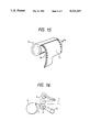
- a conventional photographic film 1 is rolled in a cylindrical cartridge 2 as shown in FIG. 15 allowing the end of the film to be withdrawn from the cartridge substantially tangentially thereto. Since the film 1 is wound around a core in the cartridge 2, the film 1 has a curled shape, as illustrated, after it has been withdrawn from the cartridge.
- the film 1 is carried while successively submerged in a series of treatment solutions.
- the film 1 is intended to be positioned between a draw-out roller 4, rotationally driven in the direction of the arrow by a driving system 3, and a nip roller 5, so that the film 1 can be conveyed to a developing tank (not shown).
- the curl of the film 1 often prevents the end of the film 1 from being properly positioned between the draw-out roller 4 and the nip roller 5, as shown by the solid line in FIG. 8. As a result, the film 1 cannot be properly conveyed or otherwise may become jammed.
- the curling of the film 1 may be corrected by removing the film in a manner that causes the film to curl in the opposite direction to its natural curl or by attaching an uncurled leader to the film.
- the decurling of the film must be performed in a dark room to avoid exposure of the film to light resulting in attendant disadvantages.
- the attaching of the leader must be performed by hand, so that not only preparation of the leader is required but much labor is required for attaching the leader.
- an object is to provide a film container adapted for automatically supplying a film to a draw-out position, and also to provide an automatic developing apparatus arranged to efficiently perform a series of development treatments by automatically supplying films to the developing apparatus.
- a film container which includes a storage portion for storing a cartridge containing a roll of film while controlling the direction of an outlet of the cartridge, and a film leading-out portion for supporting an end portion of the film drawn out from the outlet to correct the curling of the end portion of the film.
- an automatic developing apparatus which includes a holder for holding a predetermined number of containers storing the film cartridges, a conveying control mechanism for holding the containers in the holder and for individually and successively feeding out the containers, a shutter mechanism for shading a film draw-out position at all times except during the feed-out of the container, a draw-out mechanism for withdrawing the film out of the container positioned in the film draw-out position, and an ejecting mechanism for ejecting the container from the draw-out position.
- the holder and the container each have engagement portions which are fitted to each other only when the container is loaded in a proper direction.
- an automatic developing apparatus includes a holder for holding a desired number of cartridges each containing a roll of photographic film, a feed control mechanism for individually and successively feeding the cartridges to a film draw-out position, a mechanism for adjusting the angular orientation of the cartridge by rotating the cartridge in the draw-out position, a shutter mechanism for shading the draw-out position at all times except during the feed-out of the cartridge, a draw-out mechanism for withdrawing the film from the cartridge positioned in the film draw-out position, and an ejecting mechanism for ejecting the cartridge from the draw-out position.
- the holder holds the cartridges adjacent one another along a slide
- the feed-out control mechanism includes a pair of coaxially disposed arms, one of the arms supporting the lowermost cartridge and being rotatable to feed the lowermost cartridge and the other arm acting to block the adjacent cartridge upon rotation of the first arm.
- the holder has a preferential treatment gate for guiding another cartridge not being held in the holder into the film draw-out position prior to the cartridges being held in the holder.
- a film end treatment device is provided for pulling the film out of the cartridge and for cutting the film to a desired length.
- the developing apparatus includes a section for developing a leader-less photographic film (having no leader attached to its end), and a section for developing a photographic film having a leader attached thereto in a side by side relationship.
- the container is designed to prevent the end of the film from curling so that the film will not interfere with the conveyance of the film along the holder.
- the carrying and positioning of the film container to the film draw-out position and the withdrawing of the film are performed automatically, so that automatic developing can be made speedily and steadily.
- the automatic developing apparatus has a mechanism for rotating the cartridge so that it is disposed in the proper orientation in the draw-out position to make it possible to automatically withdraw the film from the cartridge.
- the film partially withdrawn from the cartridge can be brought into the carrying means properly by rotating the cartridge in the proper direction after sliding the leader-less film down from the holder. As a result, the film can be carried properly.
- Examples of the film carrying means used herein are nip roller, sprocket, belt, etc.
- the end portion of the film drawn out of the cartridge can be related to these carrying means by turning the film outlet of the cartridge so as to oppose the carrying means.
- the cartridge With respect to the rotation of the cartridge, the cartridge can be rotated by urging against the film slightly protruding from the cartridge so as to rotate the cartridge to a proper position, that is, to a position where the end of the film is in contact with the carrying means.
- a pair of nip rollers for pulling out the film may be provided so that one of the nip rollers can serve as a movable roller moving toward the other nip roller while retaining the film therebetween.
- the film cannot be brought into contact with the carrying means properly if the end of the film is not extended by a predetermined length from the cartridge.
- the tongue portion at the end portion of the film be cut off at a right angle.
- a tongue draw-out device is used for pulling the film out of the cartridge. The film end treatment work can be carried out very easily and smoothly by providing the tongue draw-out device in the inside of the apparatus in the vicinity of the holder and further providing an end treatment mechanism for cutting the end of the film in the tongue draw-out device.
- the holder may be provided obliquely so that the cartridges are arrange adjacent one another.
- the one-by-one supply of the cartridges is performed by suitably releasing the supporting of the lowermost cartridge.
- the upper cartridges need to be supported so as not to slide down.
- the operation of releasing the lowermost cartridge and the operation of supporting the upper cartridges can be carried out simultaneously.
- the cartridges are supplied to the film draw-out portion in order starting from the lowermost cartridge.
- the treatment order needs to be changed to allow introduction of the preferred film. Therefore, at least one portion of the holder above the inclined surface thereof, or more preferably, a portion of the holder below the lower most cartridge, may be formed in an open state or in an openable state.
- the cartridge having the preferential film can be placed in any suitable position. Further, a different loading inlet serving as a preferential treatment gate may be formed in the holder.
- the cartridges can be supplied automatically without use of any leader. Accordingly, the conventional work for attaching a leader to each film can be omitted, so that the developing work can be simplified.
- the leader-less films are drawn out of the cartridges and successively carried into the respective tanks and submerged in treatment solutions, so that the leader-less films are successively treated. Because the leader-less film is slightly curled at its end, the film must be guided by guide members and the like properly so as not to diverge from the carrier path.
- the leader-less film can be carried more surely by forming the carrier path like a slit in addition to the carrying means including nip rollers or the like.
- both a section for treating a leader-less film and a section for treating a leader-containing film may be provided in the apparatus. It is to be understood that the meaning of "both" is that the two types of films can be treated, and that the two treatment sections need not always be provided. For example, the configuration may be such that the two types of films may be treated by only one treatment section. On the contrary, in the case where two types of treatment lines are provided, common treatment tanks may be used.
- a carrier rack having the carrying means may be used for both treatment lines. Further, a part of a system for driving the carrier rack may be used for both lines. Further, treatment tanks and carrier racks may be provided separately with respect to the respective treatment lines. In this case, a partition wall between the tank in one treatment line and the tank in the other treatment line may be formed so as to be able to be opened. When occasion arises, a part of the partition wall may be opened to mix treatment solutions of the same kind in the two lines so that they are of the same strength or the like.
- films such as 135-size films, 110-size films, brownie size films, etc.
- films can be treated by one automatic developing apparatus.
- 135-size leader-less films can be treated by one treatment section
- brownie size films each having a leader attached thereto can be treated by the other treatment section.
- FIG. 1 is a perspective view of a film container according to an embodiment of the present invention
- FIG. 2 is a perspective view of the film container in an opened state
- FIG. 3 is a sectional view of the film container according to the invention.
- FIG. 4 is a configuration diagram of an automatic loader according to the invention.
- FIG. 5 is a cross-sectional view of the holder according to the invention.
- FIG. 6 is a configuration diagram of an automatic developing apparatus according to the present invention.
- FIG. 7 is a configuration view showing a second example of an automatic loader
- FIG. 8 is a perspective view of the feed-out mechanism according to the present invention.
- FIGS. 9(a), 9(b) and 9(c) are side views showing the operation of the feed-out mechanism
- FIG. 10 is a side view showing the structure of the supply supporting portion according to the present invention.
- FIG. 11 is a typical constituent view showing the configuration of the film end treatment device according to the present invention.
- FIG. 12 is a perspective view illustrating an example of the configuration of the treatment tanks
- FIG. 13 is a vertical sectional view showing the configuration of the treatment tanks illustrated in FIG. 12;
- FIG. 14 is a vertical sectional view showing another example of the configuration of the treatment tanks.
- FIG. 15 is a perspective view showing the conventional arrangement where film is withdrawn from the film cartridge.
- FIG. 16 is an explanatory view showing a conventional film conveying system.
- FIGS. 1 through 6 show an example of the film container according to the present invention.
- FIGS. 4 through 6 show the configuration of an example of the automatic developing apparatus using the film cartridge. In the following description of the embodiments, the film container and the automatic developing apparatus will be described successively.
- the container is substantially shaped like a rectangular parallelepiped and includes two pivotally attached half portions which can be opened along diagonally extending line a.
- a pair of guide portions 13 are respectively provided so as to extend from opposite end portions of an upper face 12 and a pair of guide portions 15, opposite to the pair of guide portions 13, are further provided in opposite end portions of a front face 14 perpendicular to the upper face 12. Additionally, a pair of guide projections 16 are provided on the upper face 12 opposite the pair of guide portions 13. As explained below, the guide projections 16 serve as guides for supplying the container 11 to the automatic developing apparatus.
- the inside of the container 11 includes a substantially cylindrical storage portion 21.
- the container 11 is arranged so as to be opened and closed by pivoting one half of the container with respect to the other half about hinge 22, as shown in FIGS. 2 and 3.
- a half of the storage portion 21 is accessible, as shown in FIG. 2 making it easy to store the cartridge 2 in the container.
- step portions 13a are formed in lower surfaces of the pair of guide portions 13 and corresponding step portions 15a are further formed in upper surfaces of the pair of guide portions 15.
- slits are formed by the step portions 13a and 15a to guide the opposite lateral side portions of the film. These slits correspond to a film leading-out portion defined in the present invention.
- the cartridge 2 When the cartridge 2 is to be stored in the container 11 having the aforementioned structure, the cartridge 2, with an end of the film withdrawn therefrom, is stored in the storage portion 21 after the container 11 is opened along the hinge 22.
- the film 1 is withdrawn and fitted in the guide portions 15a whereupon the container 11 is closed.
- the opposite sides of the film 1 are positioned by the slits constituted by the step portions 13a and 15a as shown in FIG. 1, so that the film 1 can be withdrawn in a direction of the arrow X shown in FIG. 3.
- the forward end of the film 1 is generally uneven having a tongue portion extending therefrom. Before or after the film is loaded in the container 11, the forward end of the film 1 is cut straight across as shown in the FIG. 1.
- the cartridge 2 is generally shaped substantially like a cylinder, it is noted that the outer surface of the film draw-out portion 2a of the cartridge is substantially planar.
- a partial wall 21a of the storage portion 21 adjacent the film draw-out portion 2a of the cartridge is also partially shaped in a planar manner as shown in FIG. 3, and extends to the slits. That is, the partial wall 21a extends to the film leading-out portion for withdrawing the film 1.
- the film draw-out portion 2a is positioned adjacent the planar partial wall 21a of the storage portion 21 so that the film 1 can be pulled therealong through the slits in a straight manner.
- the cartridge 2 is held and the curling of the film 1 is corrected.
- the cartridge 2 in the storage portion 21 is prevented from rotating, so that the film 1 can be pulled out smoothly and can be supplied automatically with ease.
- FIG. 4 is a typical structural diagram of an automatic loader
- FIG. 5 is a cross sectional view of important part of the holder having a function of guiding the container
- FIG. 6 is a diagram of the automatic developing apparatus.
- the automatic loader 31 includes a holder 32 for holding containers 11 arrange one adjacent and above another, a feed-out control mechanism 33 for individually supplying the containers to the automatic developing apparatus 100 (which will be described later) a preferential treatment gate 34 for preferentially subjecting a desired container 11 to development, a shutter mechanism 35 for preventing light from entering the inside of the automatic developing apparatus 100 and for successively feeding the containers 11 to the automatic developing apparatus 100, a mechanism 36 for withdrawing the film 1, a mechanism 37 for cutting the film 1, carrier rollers 38 for supplying the film 1 to a developing tank (which will be described later) or the like, a withdrawal mechanism 39 for withdrawing the cartridges 11 after the withdrawal of the film 1, and a withdrawal pocket portion 40.
- the cross-sectional shape of the holder 32 substantially corresponds to the external shape of the container 11. That is, two guide grooves 41 are formed in the upper wall to receive the guide projections 16 of the container 11. Further, the holder 32 is formed cylindrically so that a desired number of containers 11 can be retained and slid down while guided by the guide grooves 41.
- the holder 32 is obliquely attached to a housing 101 of the automatic development apparatus 100 in the manner illustrated in FIG. 4.
- the container 11 When a container 11 is to be inserted into the holder 32, the container 11 is inserted such that the guide projections 16 are guided by the two guide grooves 41 with the front face of the container 11 facing forward, that is, with the draw-out direction of the film 1 facing diagonally downwardly in FIG. 4.
- the guide grooves 41 are formed so as to be biased to one side to prevent mistaken insertion of the container 11. Accordingly, when the container 11 is accidentally attempted to be inserted in an inverted manner, the guide projections 16 cannot be fitted into the guide grooves 41 so as to prevent the erroneous insertion.
- the feed-out control mechanism 33 is provided to successively and individually supply a plurality of containers 11 to a standby position between the feed-out control mechanism 33 and the .shutter mechanism 35 to avoid simultaneously supplying the containers 11 to the automatic developing apparatus 100.
- the stopper 33 can be driven using a plunger-and-solenoid arrangement, or the like.
- the preferential treatment gate 34 is formed so as to be able to be opened and closed as shown in FIG. 4, in which a part of the holder 32 is shown by the dotted line. When there is any film to be subjected to a developing treatment prior to the container being inserted into the holder 32, the preferential treatment gate 34 is opened so that the container to be preferentially treated can be inserted between the feed-out control mechanism 33 and the shutter mechanism 35.
- the shutter mechanism 35 prevents light from entering into the automatic developing apparatus 100 and feeds the container 11, disengaged by the feed-out control mechanism 33, into the automatic developing apparatus 100.
- the shutter mechanism 35 is normally shut but is controlled to be opened in order to feed the container 11 to the automatic developing apparatus 100. Specifically, when the shutter mechanism 35 is opened, the container 11 is slid from the standby position down along a carrier path 42 and positioned in a film draw-out position.
- the film draw-out mechanism 36 comprises a draw-out roller 44 and a nip roller 43 which are respectively located in lower and upper positions to nip the film 1 therebetween to thereby withdraw the film 1.
- the draw-out roller 44 is driven to rotate in the direction of the arrow shown in FIG. 4 by a driving mechanism 46 constituted by an electric motor, or the like.
- the axial length of the pair of rollers 43 and 44 is set so that the rollers can be fitted into cavity portions formed by the pair of guide portions 13 and 15 provided in the container 11.
- the end portion of the film 1 is not curled, but rather is flat. Accordingly, the film 1 can be easily nipped by the pair of rollers 43 and 44. Further, the film 1 can be pulled straight by rotating the rollers 43 and 44. Further, because the end portion of the film 1 is not curled, the container 11 can be automatically conveyed down the holder 32 without film interference. The film 1 thus pulled out is carried by the carrier rollers 38 through a guide portion 47 and supplied to a developing tank or the like.
- the withdrawal mechanism 39 is arranged so that a part 45 of the bottom of the carrier path 42 can be opened, as shown by the dotted line, to withdraw the container 11 after the film 1 has been completely withdrawn.
- the opening and shutting of the bottom part 45 is driven by a driving mechanism including a plunger-and-solenoid 46.
- a tongue draw-out device 81 for withdrawing the end portion of the film from the cartridge 2 is provided in the vicinity of the holder 32 in the automatic loader 31.
- the film 1 is rolled so as to be entirely contained in the cartridge 2. Therefore, the end of the film 1 must be withdrawn from the cartridge 2 before the holder is loaded with the cartridge 2.
- FAE500 made by Fuji Photo Film Co., Ltd. may be used as the tongue draw-out device 81 which will be described in greater detail below.
- a developing tank 105 In the housing 101, a developing tank 105, a bleaching tank 106, a fixing tank 107, three washing tanks 108 and a dryer portion 109 are arranged in the stated order from left to right in FIG. 6. Carrier rollers, as shown only in the developing tank 105, are provided in the respective tanks from the developing tank 105 to the washing tanks 108. The aforementioned automatic loader 31 is provided in the upper left portion of the housing 101.
- the film 1 thus withdrawn is submerged in a developing solution while carried by carrier rollers 111 and inversion rollers 112 provided in the developing tank 105.
- the film 1 is then carried to the bleaching tank 106 by carrier rollers (not shown) and inversion rollers 112 and submerged therein.
- the film 1 is passed though the fixing tank 107 and submerged in a fixing solution and is then carried into the washing tanks 108. After being washed in the three successive washing tanks 108, the film 1 is carried into the dryer portion 109.
- the film 1 is successively submerged in the treatment solutions in the respective tanks.
- the path for carrying the film 1 is formed like a slit, so that the film 1 is carried through the slit by carrier rollers 111 and inversion rollers 112.
- the dryer portion 109 blows hot air on the filter, as shown by the arrows in the carrier path of the film 1.
- the film 1 dried by the hot air may be ejected from the automatic developing apparatus or may be supplied to a printing apparatus (not shown).
- the film 1 withdrawn from the container 11 is carried into the respective tanks successively.
- the automatic loader 31 operates as described above to automatically supply the film 1 to the next container 11. Accordingly, automatic supply can be made without any structure of attaching a leader tape to the film 1. Consequently, developing work can be simplified.
- FIG. 7 is a structural view of the automatic loader 51
- FIG. 8 is a perspective view showing the structure of the feed-out mechanism 53
- FIGS. 9(a), 9(b) and 9(c) are side views showing the operation of the feed-out mechanism 53
- FIG. 10 is a side view showing the structure of the mechanism 56 for withdrawing the film 1 rolled in the holder 52.
- parts which are the same as those discussed in regard to the first embodiment are identified by like numerals.
- the automatic loader 51 comprises a diagonally disposed slide-like holder 52 having an opened upper surface, a feed-out mechanism 53 for successively and individually withdrawing the cartridges from the holder and feeding them to the automatic developing apparatus 100, a shutter mechanism 54 for preventing light from entering into the apparatus 100 after the completion of the feed-out operation, a supply supporting portion 55 for supporting the fed-out cartridge 2 to a position for withdrawing the film 1 from the cartridge 2, a draw-out portion 56 for withdrawing the film 1 from the cartridge 2, and an ejecting mechanism 57 for ejecting the cartridge 2 on the basis of the detection of the end of the film 1.
- the holder 52 is obliquely attached to the apparatus 100 in the same manner as the holder 32 described above in the previous embodiment.
- the shape of the holder 52 is, however, simplified greatly as compared to the shape of the holder 32. That is, the holder 52 has a shape formed by removing the upper side of an elongate box. In other words, the holder 52 is shaped like a U-shaped slide.
- the inner lateral width of the holder 52 is slightly larger than the length of the cartridge 2. Further, the length of the holder 52 is suitably set to correspond to the number of cartridges to be arranged thereon.
- the cartridges 2 are arranged in the holder 52 so that the film draw-out portion 2a is located on the lower side and the end portion of the film 1 is oriented upwardly along the bottom portion of the holder 1 as shown in FIG. 7. Accordingly, after a single or plurality of cartridges 2 are arranged, the cartridge 2 can slide down by their own weight toward the apparatus 100.
- the feed-out mechanism 53 comprises a first supporting member 62 and a second supporting member 63 which serve as a unitary structure which is rotatable a predetermined angle on a rotation shaft 61.
- the first supporting member 62 is comprised of a pair of L-shaped turning members 62a each having an end fixed to the rotation shaft 61, and a supporting plate 62b extending between the respective forward ends of the turning members 62a.
- the length of each of the turning members 62a is set to correspond to the position where the rotation shaft 61 is attached and the position where a cartridge 2 is supported in a standby position.
- the rotation shaft 61 is attached at a predetermined position on the apparatus 100 so that it can be freely reciprocatingly rotated by a driving means such as a motor (not shown).
- the supporting plate 62b is fixed to the lower side of the pair of turning members 62a so that a U-shaped frame is constituted by the supporting plate 62b and the front end portions of the pair of turning members 62a.
- a cartridge 2 is supported as shown in FIG. 7, the cylindrical portion and opposite side portions of the cartridge 2 are each supported by the U-shaped frame.
- the second supporting member (stopper) 63 is comprised of a pair of turning members 63a each having an end fixed to the rotation shaft 61, and a fixed supporting plate 63b extended between the forward ends of the turning members 63a.
- the supporting plates 62b and 63b are each rotatable in the same direction at a predetermined distance. The function of the second supporting member 63 will be described later in conjunction with the feed-out of the cartridge 2.
- the shutter mechanism 54 is arranged so that it is open when the cartridge 2 is fed to the apparatus 100, and is closed at all other times.
- the opening and shutting operation is carried out in correspondence with the control of the feed-out mechanism 53.
- the supply supporting portion 55 includes a U-shaped portion to support the cartridge 2 fed-out from the holder 52. Specifically, at one end of the supply supporting portion 55, a supporting piece 64 is formed to be fitted to the cylindrical portion of the cartridge 2 so that the cartridge 2 can be positioned rotatably.
- a long guide hole 65 and a supporting shaft 66 are provided for supporting the cartridge so as to be slightly movable in the left and the right in the drawing and rotatable as shown in the dotted line.
- a stoppage projection 67 is provided to rotate the supply supporting portion 55 from the position illustrated by the solid line to the position illustrated by the dotted line in correspondence with the operation of the ejecting mechanism 57.
- the stoppage projection 67 is engaged with one end of the ejecting mechanism 57 (which will be described later).
- the film draw-out mechanism 56 comprises a sprocket 68 and a nip roller 69 provided on the right side as illustrated in FIG. 7.
- the structure of the film draw-out mechanism 56 can be understood easily by referring to FIGS. 7 and 10.
- the sprocket 68 is rotatably attached to the apparatus 100 and has projections (not shown) formed in its opposite side portions which are engageable with perforations (film feed holes) 1a formed in opposite side portions of the film 1.
- the nip roller 69 includes a turning member 69a rotatably attached to one end of the supply supporting portion 55 so at to be pivotable coaxially with the cartridge, a turning member 69b rotatable by a motor M, and a roller 69c rotatably secured to the forward ends of the turning members 69a and 69b.
- the nip roller 69 is positioned at the position shown in the solid line in FIG. 7.
- the film draw-out portion 2a faces upwardly because cartridges on the holder 52 are piled up so that the forward end of the film 1 is turned upward.
- the forward end portion of the film 1 drawn out from the film draw-out portion 2a is positioned within the range of pivot movement of the roller 69c.
- the side of the film draw-out mechanism 56 i.e., the left in FIG.
- the roller 69c is behind the film 1 as shown in FIG. 10.
- the roller 69c or the nip roller 69 is pivoted from the position of the solid line to the position of the dotted line, the forward end of the film 1 is urged in the clockwise direction in FIG. 7 by the roller 69c.
- the forward end portion of the film 1 is pressed against the sprocket 68. Accordingly, the film 1 is drawn out of the cartridge 2 by turning the sprocket 68.
- the vertical wall portion 55a formed at the right end of the supply supporting portion 55, acts as a stop for preventing lateral movement of the cartridge.
- the ejecting mechanism 57 comprises a moving member 71 provided so as to be movable in the left and right directions, a tension spring 72 for urging the moving member 71 to the left, and a switch 73 for detecting the position of the supply supporting portion 55.
- An elongate guide hole 72a extending left to right in the drawings is formed in the moving member 71.
- Two guide pins 72b are inserted into the guide hole 72a at predetermined positions so that the moving member 71 is restricted to move in the left and right directions.
- the stoppage projection 67 formed in the lower portion of the supply supporting portion 55 is engaged with one end of the moving member 71. While the film 1 is withdrawn, the entire supply supporting portion 55 is pulled to the right in FIG. 7 by the cartridge 2. In this state, however, the tension spring 72 prevents the moving member 71 from moving a sufficient distance to push switch 73. As a result, the supply supporting portion 55 is maintained in the state shown in the solid line in FIG. 7, so that withdrawal of the film 1 is continued.
- FIGS. 7 and 9(a) A series of operations from the feed-out of the cartridge 2 to the ejection thereof in the automatic loader 51 will be described hereunder.
- the feed-out mechanism 53 is positioned as shown in FIGS. 7 and 9(a) so that the lower most end of the holder 52 is blocked by the first supporting member 62 (FIG. 8).
- a desired number of cartridges 2 are supported by the first supporting member 62 so that they are prevented from sliding down.
- the cartridges 2 are aligned along the inclination of the holder 52 in an oblique manner.
- the cartridges 2 are arranged such that the film draw-out portion 2a faces downwardly and the forward end of the film 1 faces upwardly. The cartridges are easily arranged in this position due to the manner in which the holder 52 is opened at its upper portion.
- the feed-out mechanism 53 is driven in the counterclockwise direction by starting the apparatus 100.
- the lower most cartridge 2 supported by the first supporting member 62 begins to slide down in correspondence to the movement of the first supporting member 62 as shown in FIG. 9(b).
- the stopper 63 is urged between the lowermost cartridge 2 and the next upper cartridge 2 to prevent the upper cartridge 2 from sliding down. Because the width of the stopper 63 is smaller than the width of the first supporting member 62 as shown in FIG. 8, the cylindrical portion of the upper cartridge 2 is supported to prevent the upper cartridge 2 from sliding down.
- the shutter mechanism 54 is driven synchronously so that a carrier path for sliding down the cartridge 2 is temporarily formed between the holder 52 and the supply supporting portion 55. Accordingly, the lowermost cartridge 2 is fed out so as to slide down onto the supply supporting portion 55 without colliding with the shutter mechanism 54.
- the feed-out mechanism 53 When the feed-out of the lowermost cartridge 2 is finished, the feed-out mechanism 53 is rotated in the clockwise direction so that the next cartridge 2, as new lowermost one, is supported by the supporting member 62.
- the operation is explained as follows by reference to FIGS. 9(a) through 9(c).
- the position of the feed-out mechanism is successively changed from the state of FIG. 9(c) to the state of FIG. 9(b) and, thereafter to the state of FIG. 9(a).
- the feed-out mechanism 53 Each time the feed-out mechanism 53 returns to the position illustrated in FIG. 9(a), the number of the cartridges 2 is decreased by one.
- the shutter mechanism 54 After a single cartridge has been fed as described above, the shutter mechanism 54 returns correspondingly to cover the lower opening of the feed-out mechanism 53. As a result, the lower portion of the holder 52 is perfectly shaded, so that light is prevented from entering into the apparatus 100. Accordingly, even in the case where the film 1 is withdrawn from the cartridge 2, the film 1 is free from exposure.
- the film 1 is continuously withdrawn from the draw-out portion 2a by the rotation of the sprocket 68, so that the film 1 is submerged in the developing tank 105 as described above with reference to FIG. 6.
- the treatment downstream of the developing tank has been described previously.
- the supply supporting portion 55 as a whole is pulled toward the draw-out mechanism 55, or to the right in FIG. 7, as well. Because, however, the stoppage projection 67 is engaged with one end of the moving member 71 and the moving member 71 is urged to the left by the action of the spring 72, the balance between the pulling force resulting from withdrawal of the film 1 and the pulling force resulting from the spring 72 prevents the supply supporting portion 55 from moving to the draw-out mechanism 56 side. Further, the moving member 71 is also kept in a balancing state, so that the moving member 71 does not move to the left. Accordingly, the switch 72 provided in the vicinity of the moving member 71 remains in an off state.
- the cutter 58 is driven by a control circuit (not shown) to perform cutting of the film 1.
- the nip roller 69 is turned in the counterclockwise direction to release the nipping of the forward end of the film 1 between the nip roller 69 and the sprocket 68.
- a motor is operated to rotate the supply supporting portion 55 about the fulcrum pin 66 in the direction of clockwise rotation.
- the cartridge 2 is moved away from the draw-out mechanism 56 and, furthermore, the supply supporting portion 55 is rotated clockwise. Accordingly, the two are turned as one body from the position of the solid line to the position of the dotted line in FIG. 7.
- the ejecting operation can be carried out by the following structure.
- the sprocket 2 is in a state where it is merely put on the supply supporting portion 55. Accordingly, if the supply supporting portion 55 is further turned from the position of the dotted line, for example, to form an angle of not smaller than 90°, the cartridge 2 is dropped from the supply supporting portion 55 to the withdrawal pocket portion 40 due its own weight.
- the cartridge 2 is, however, positioned by the vertical wall portion 55a and the supporting piece 64, it may be difficult for the cartridge 2 to drop. Further, a large space is required for rotating the supply supporting portion 55 by an angle of greater than 90°.
- an insertion hole 55b is formed in the lower portion of the supply supporting portion 55 adjacent the cartridge and a projection 55c is provided on the locus of rotation of the insertion hole 55b for forcing the cartridge from the supporting portion.
- the projection 55c is inserted into the insertion hole 55b when the supply supporting portion 55 is further turned from the position of the dotted line, so that the cartridge 2 can be forced out by the forward end thereof. Accordingly, ejection can be performed more readily.
- the stoppage projection 67 is also turned. Accordingly, the force of temporarily pressing the moving portion 71 to the right is released, so that the moving member 71 is moved to the left due to the tension of the spring 72 and through the guide function of the guide hole 72a and the guide pins 72b. Accordingly, the switch 73 is turned off to operate the control circuit to thereby return the supply supporting portion 55 from the position of the dotted line to the position of the solid line.
- the stoppage projection 67 is engaged with one end of the moving member 71 again to press the moving member 71 to the right against the spring 72.
- the automatic loader is returned to its initial state, that is, the standby state to prepare for the feed-out of the next cartridge 2.
- a film 1 is to be preferentially treated in the period in which the automatic loading of the cartridge 2 is carried out as described above, preferential treatment can be made very easily. That is, in this embodiment, the holder 52 is open at its upper portion. Accordingly, in the case where a certain film 1 is to be treated preferentially, a number, N, of cartridges 2 piled up in the holder 52 are removed with one's hand through the opening of the holder and the cartridge 2 of the film 1 to be preferentially treated is set to the lowermost position. Removal of the cartridges can be accomplished by sliding the N cartridges 2 up along the holder 1 and then placing the cartridge 2 to be preferentially treated into the lowermost position, since the upper portion of the holder 1 is opened entirely.
- this embodiment includes the sprocket 68 for use in the film draw-out mechanism 56, it is to be understood that the present invention is not limited thereto and that the sprocket 68 may be replaced by a nip roller, a teeth-containing belt, a chain or the like. Further, it is a matter of course that the driving source for the nip roller 69 and the supply supporting portion 55 is not limited to the motor and that the motor may be replaced by a plunger, a solenoid or the like.
- the automatic loading is based on the assumption that the film protrudes from the end of the cartridge 2.
- the film 1, however, may be entirely contained in the cartridge 2 so that the forward end portion of the film 1 cannot be observed from the outside of the cartridge 2.
- the film 1 is drawn out by using the following film end treater and then the cartridge is set in the holder 52.
- FIG. 11 is a typical structural view of the tongue draw-out device 81 for withdrawing the film 1 from the cartridge 2.
- the tongue draw-out device 81 is provided in the vicinity of the automatic loader 51 so that the cartridge 2 can be loaded in the automatic loader 51 soon after the tongue is withdrawn.
- An adhesive tape 83 with release paper is rolled on a take-up roll 82.
- the tape 83 with released paper is carried to a push plate 86 through a nip roller 84 by a feed roller 85.
- the released paper 87 is removed at the forward end of the push plate 86 while the adhesive tape 83 continues to be conveyed along a the push plate 86.
- the adhesive tape 83 can be reciprocated by the feed roller 85.
- the push plate 86 is loaded so as to enter into the outlet 2a of the cartridge 2 whereupon the loading of the push plate 86 is automatically detected to start the tongue draw-out operation.
- the feed roller 85 is rotated to continuously feed the adhesive tape 83 into and out of the cartridge 2. In most cases, the tongue portion of the film is withdrawn from the cartridge 2.
- a cutter 88 is arranged in the vicinity of the push plate 86, so that the adhesive tape 83 can be cut by the cutter 88.
- the film 1 cannot yet be loaded. Rather, it is first necessary to cut the tongue portion from the film to make the end edge of the film 1 linear and parallel to the widthwise direction of the film.
- the condition that the forward end edge is linear may be insufficient.
- the film length from the cartridge 2 is limited to an allowed range (for example, about 10 mm to about 30 mm) in order to turn the cartridge 2 using the turning mechanism so as to move the forward end portion of the film 1 to a position where it can be nipped by the sprocket 68. If the length of the film extending from the cartridge 2 is outside of this range, proper operation may not be possible.
- the cutter 88 operate to cut a predetermined length portion of the film 1 withdrawn from the cartridge 2.
- a portion for limiting the position of the cartridge 2 may be provided below the cutter 88 in the drawing so that the film 1 can be cut in the condition that the motion of the cartridge 2 is limited. If the distance between the portion for limiting the position of the cartridge 2 and the cutter 88 is set to a suitable value, the film 1 can be cut so that the film 1 is drawn out by a predetermined length from the cartridge 2.
- the tongue draw-out work can be continued by cutting the adhesive tape 83 adhered to the tongue portion through the cutter 88 after cutting the film.
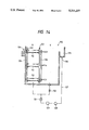
- FIGS. 12 through 14 Another example of the automatic developing apparatus will be described hereunder with reference to FIGS. 12 through 14.
- This embodiment relates to treatment tanks in the automatic developing apparatus.
- the same parts as the parts in FIG. 6 are identified by like numerals.
- a developing tank 105, a bleaching tank 106, a fixing tank 107 and three washing tank 108 are separated into a treatment system X for treating a leader-less film and a treatment system Y for treating a leader-containing film by a partition plate 121.
- carrier rollers 111 and 112 and the like are not shown for convenience of illustration. Though not shown, the film is carried to the developing tank 105 in the same manner as described above with reference to FIG. 6.
- partition structure Although examples of the partition structure will be described hereunder, description will be limited to the partition structure of the developing tank 105, it being understood that the structure is the same for each tank.
- the developing tank 105 is partitioned by the partition plate 121 so that the width of the treatment system X is smaller than the width of the treatment system Y. This is caused by the fact that the width of the leader is larger than the width of the film and, accordingly, the leader-less film treatment system X is set to be adjusted to the width of the film whereas the leader- containing film treatment system Y requires a sufficient width to accommodate the leader.
- Each of the carrier racks is constituted by a carrier roller 112 and a pair of side plates 122 typically shown.
- the carrier roller 112 is attached to the pair of side plates 122 so as to be rotatable.
- a rotating force is transmitted to the carrier roller 112 by a gear 124 mounted to a rotation shaft 123.
- Carrier racks are also provided in the treatment system Y. Because each of the carrier racks in the treatment system Y can be formed in the same manner as each of the carrier racks in the treatment system X, both illustration and description of the carrier racks in the treatment system Y are omitted.
- a tank 125 for circulating the developing solution in the developing tank is provided in the left side of the developing tank 105, so that the developing solution overflowing from the developing tank can be reserved.
- a pipe 127 is connected to an outlet 126 formed in the lower end of the tank 125.
- a heater 128 for heating the developing solution and a thermometer 129 are provided in the pipe 127. The heater 128 is provided to heat the developing solution to a desired temperature to thereby improve the developing treatment rate, and the thermometer is provided to monitor the temperature of the developing solution.
- a pump 131 is provided to circulate the developing solution to the treatment systems X and Y.
- a valve 132 is provided in the return current path to the treatment system Y.
- the valve 132 has the following function as related to a partition cover 133 provided on the partition plate 121.
- the developing solution is supplied to the treatment systems X and Y and further circulated through an opening in the valve 132 and an opening in the partition cover 133 and pumped by the pump 131. Accordingly, the developing treatment of the leader-less film and the developing treatment of the leader-containing film can be carried out simultaneously by using the treatment systems X and Y.
- the developing treatment of the leader-less film is carried out alone.
- the valve 132 is shut and the partition cover 133 is shut.
- the supply of the developing solution to the treatment system Y and the stopping thereof can be performed, so that the supply and return current of the developing solution to the treatment system X can be performed independently.
- the developing treatment of the leader-less film can be carried out exclusively.
- the carrier rollers 112 in the treatment systems X and Y may be driven separately so that energy may be saved by stopping the driving of the carrier racks when the treatment system Y is not used.
- the partition plate 121 may be removed; the tank 125 may be provided in the treatment system Y side; and the inner side plates 122 may be used as the carrier racks in the treatment system Y.
- the treatment tanks are commonly used in the treatment systems X and Y, portions of the carrier racks are common to both systems, and the carrier rollers are driven by a common driving source. Accordingly, not only can the structure be simplified, but the developing treatments in the treatment systems X and Y can be carried out. Furthermore, the developing treatment in either of the treatment systems can be performed exclusively.
- the carrier rollers 112 may be driven by a chain 135.
- the treatment system Y may be formed so that the film is carried by a belt 136 having teeth thereon.
- the driving source for the carrier rollers 112 and the driving source for the belt 136 may be provided separately.
- the treatment system X has slit-shaped carrier paths and carrier means mainly adapted for the treatment of a 135-size film.
- the treatment system Y has the same carrier roller group as the conventional carrier, by which a 110-size film or a brownie size film as well as a 135-size film can be treated.
- the film to be treated is a 135-size film which can be originally treated in the treatment system X
- the conveyance of the film in the treatment system X may be poor if perforations of the film are in poor condition or if the film is wet. In such case, the film can be treated by the treatment system Y. Accordingly, the problem in poor conveyance can be solved.
- the film container according to the present invention can retain the film while remedying the curling of the film drawn out of the cartridge. Accordingly, the film can be supplied steadily and easily to the automatic developing apparatus.
- the automatic developing apparatus is formed so that not only a desired number of film containers can be held by a holder, but the film containers may be individually and successively conveyed and positioned to a film draw-out position to enable the film to be supplied to the developing tank and the like after withdrawing the film through the film draw-out mechanism while remedying the curling of the film. Accordingly, there is no failure caused by the curling of the film. As a result, automatic supply of the film can be made efficiently and exactly.
Landscapes
- Physics & Mathematics (AREA)
- General Physics & Mathematics (AREA)
- Photographic Developing Apparatuses (AREA)
Abstract
Description
Claims (8)
Applications Claiming Priority (4)
| Application Number | Priority Date | Filing Date | Title |
|---|---|---|---|
| JP15089691 | 1991-05-28 | ||
| JP3-150896 | 1991-05-28 | ||
| JP4087552A JP2805413B2 (en) | 1991-05-28 | 1992-03-12 | Film cartridge and automatic developing device |
| JP4-87552 | 1992-03-12 |
Publications (1)
| Publication Number | Publication Date |
|---|---|
| US5311237A true US5311237A (en) | 1994-05-10 |
Family
ID=26428815
Family Applications (1)
| Application Number | Title | Priority Date | Filing Date |
|---|---|---|---|
| US07/889,433 Expired - Lifetime US5311237A (en) | 1991-05-28 | 1992-05-28 | Film container and automatic developing apparatus |
Country Status (4)
| Country | Link |
|---|---|
| US (1) | US5311237A (en) |
| EP (2) | EP0516105B1 (en) |
| JP (1) | JP2805413B2 (en) |
| DE (2) | DE69232198T2 (en) |
Cited By (5)
| Publication number | Priority date | Publication date | Assignee | Title |
|---|---|---|---|---|
| US5471275A (en) * | 1993-11-29 | 1995-11-28 | Fuji Photo Film Co., Ltd. | Photosensitive material processing apparatus |
| US5564644A (en) * | 1993-06-03 | 1996-10-15 | Noritsu Koki Co., Ltd. | Light shielding magazine for a film cartridge |
| US5806778A (en) * | 1996-04-15 | 1998-09-15 | Fuji Photo Film Co., Ltd. | Cartridge adapter |
| US5825462A (en) * | 1994-12-13 | 1998-10-20 | Noritsu Koki Co., Ltd. | Film cartridge storage apparatus |
| US6698945B2 (en) | 2001-08-24 | 2004-03-02 | Noritsu Koki Co., Ltd. | Automatic photo film feeding apparatus |
Families Citing this family (3)
| Publication number | Priority date | Publication date | Assignee | Title |
|---|---|---|---|---|
| DE69525404T2 (en) * | 1994-09-21 | 2002-11-21 | Noritsu Koki Co., Ltd. | Apparatus for processing a photographic film |
| US5488448A (en) * | 1994-11-09 | 1996-01-30 | Eastman Kodak Company | Film cartridge recovery tool |
| DE19539719A1 (en) * | 1995-10-25 | 1997-05-07 | Agfa Gevaert Ag | Device for automatically removing a photographic film from a cartridge |
Citations (5)
| Publication number | Priority date | Publication date | Assignee | Title |
|---|---|---|---|---|
| US3568587A (en) * | 1968-07-26 | 1971-03-09 | Jerome D Laval | Photographic paper feeding attachment for processor |
| DE2545215A1 (en) * | 1975-10-09 | 1977-04-21 | Agfa Gevaert Ag | DAYLIGHT DEVICE |
| US4253788A (en) * | 1978-08-08 | 1981-03-03 | Cx Corporation | Film unloading and handling mechanism |
| JPS61151654A (en) * | 1984-12-26 | 1986-07-10 | Fuji Photo Film Co Ltd | Film feeding device |
| EP0349448A1 (en) * | 1988-06-30 | 1990-01-03 | KIS PHOTO INDUSTRIE S.a.r.l. | Apparatus to introduce an end of a film unrolled from a cassette to a developing apparatus for films, and a module for using this apparatus |
Family Cites Families (6)
| Publication number | Priority date | Publication date | Assignee | Title |
|---|---|---|---|---|
| JPS532570A (en) * | 1976-06-29 | 1978-01-11 | Tamura Electric Works Ltd | Method for metallic colored ornamentation of synthetic resin mouldings |
| JPS5343287A (en) * | 1976-09-30 | 1978-04-19 | Nat Jutaku Kenzai | Device for preventing slippage of position of plate body |
| IT7920640U1 (en) * | 1979-01-29 | 1980-07-29 | Falomo Lodovico | DEVICE FOR SIMULTANEOUS TRANSFER OF PHOTOGRAPHIC PAPER IN STRIPS FROM ROLL CASSETTES TO DEVELOPERS. |
| DE3110622A1 (en) * | 1981-03-18 | 1982-09-30 | Agfa-Gevaert Ag, 5090 Leverkusen | FILM CARTRIDGE AND / OR RELATED CAMERA |
| JP2801656B2 (en) * | 1988-07-22 | 1998-09-21 | 富士写真フイルム株式会社 | Photo film patrone |
| JPH0375637A (en) * | 1989-08-17 | 1991-03-29 | Fuji Photo Film Co Ltd | Photographic film cartridge |
-
1992
- 1992-03-12 JP JP4087552A patent/JP2805413B2/en not_active Expired - Fee Related
- 1992-05-27 DE DE69232198T patent/DE69232198T2/en not_active Expired - Lifetime
- 1992-05-27 EP EP92108984A patent/EP0516105B1/en not_active Expired - Lifetime
- 1992-05-27 DE DE69231425T patent/DE69231425T2/en not_active Expired - Lifetime
- 1992-05-27 EP EP97105440A patent/EP0790527B1/en not_active Expired - Lifetime
- 1992-05-28 US US07/889,433 patent/US5311237A/en not_active Expired - Lifetime
Patent Citations (5)
| Publication number | Priority date | Publication date | Assignee | Title |
|---|---|---|---|---|
| US3568587A (en) * | 1968-07-26 | 1971-03-09 | Jerome D Laval | Photographic paper feeding attachment for processor |
| DE2545215A1 (en) * | 1975-10-09 | 1977-04-21 | Agfa Gevaert Ag | DAYLIGHT DEVICE |
| US4253788A (en) * | 1978-08-08 | 1981-03-03 | Cx Corporation | Film unloading and handling mechanism |
| JPS61151654A (en) * | 1984-12-26 | 1986-07-10 | Fuji Photo Film Co Ltd | Film feeding device |
| EP0349448A1 (en) * | 1988-06-30 | 1990-01-03 | KIS PHOTO INDUSTRIE S.a.r.l. | Apparatus to introduce an end of a film unrolled from a cassette to a developing apparatus for films, and a module for using this apparatus |
Cited By (5)
| Publication number | Priority date | Publication date | Assignee | Title |
|---|---|---|---|---|
| US5564644A (en) * | 1993-06-03 | 1996-10-15 | Noritsu Koki Co., Ltd. | Light shielding magazine for a film cartridge |
| US5471275A (en) * | 1993-11-29 | 1995-11-28 | Fuji Photo Film Co., Ltd. | Photosensitive material processing apparatus |
| US5825462A (en) * | 1994-12-13 | 1998-10-20 | Noritsu Koki Co., Ltd. | Film cartridge storage apparatus |
| US5806778A (en) * | 1996-04-15 | 1998-09-15 | Fuji Photo Film Co., Ltd. | Cartridge adapter |
| US6698945B2 (en) | 2001-08-24 | 2004-03-02 | Noritsu Koki Co., Ltd. | Automatic photo film feeding apparatus |
Also Published As
| Publication number | Publication date |
|---|---|
| DE69232198T2 (en) | 2002-03-28 |
| EP0516105A2 (en) | 1992-12-02 |
| EP0790527A1 (en) | 1997-08-20 |
| DE69231425D1 (en) | 2000-10-12 |
| JP2805413B2 (en) | 1998-09-30 |
| EP0790527B1 (en) | 2000-09-06 |
| EP0516105B1 (en) | 2001-11-14 |
| DE69232198D1 (en) | 2001-12-20 |
| EP0516105A3 (en) | 1993-08-18 |
| DE69231425T2 (en) | 2001-01-04 |
| JPH05113626A (en) | 1993-05-07 |
Similar Documents
| Publication | Publication Date | Title |
|---|---|---|
| US5231439A (en) | Photographic film handling method | |
| US4849796A (en) | Copy storing tray assembly | |
| US4797698A (en) | Film feeding apparatus | |
| EP0251338A2 (en) | Film accumulating device for developing apparatus | |
| US5311237A (en) | Film container and automatic developing apparatus | |
| EP0158806A1 (en) | Film accumulating device for developing apparatus | |
| US5612765A (en) | Film cartridge carrier | |
| EP0677771A1 (en) | Photographic printing method and apparatus | |
| US5541699A (en) | Automatic film developing apparatus | |
| JP3161597B2 (en) | Automatic developing equipment | |
| EP0677785B1 (en) | Automatic film developing apparatus and film wind-up mechanism used in the same | |
| JP3131185B2 (en) | Automatic developing equipment | |
| JPS61292642A (en) | Photograph printing developing device | |
| JP3166479B2 (en) | Automatic splicer | |
| US5897070A (en) | Automatic film unloading apparatus and intermediate film takeup cartridge of automatic film developing apparatus | |
| JP2661814B2 (en) | Film storage device | |
| JPS61203439A (en) | Automatic photographic printing device | |
| JP3145549B2 (en) | Photographic film integration equipment | |
| JPH0351852A (en) | Film feeding method and film housing magazine | |
| JP4075121B2 (en) | Photo film automatic development equipment | |
| JP2674426B2 (en) | Film guide device for automatic film processor | |
| JP2914553B2 (en) | Automatic film processing equipment | |
| JPS61151656A (en) | Detecting mechanism for film feeding device | |
| JPH0351849A (en) | Film feeder | |
| JPS61174529A (en) | Automatic photograph printing device |
Legal Events
| Date | Code | Title | Description |
|---|---|---|---|
| AS | Assignment |
Owner name: FUJI PHOTO FILM CO., LTD., JAPAN Free format text: ASSIGNMENT OF ASSIGNORS INTEREST.;ASSIGNORS:KAWADA, KEN;TANAKA, TADASHI;REEL/FRAME:006143/0367 Effective date: 19920520 |
|
| STCF | Information on status: patent grant |
Free format text: PATENTED CASE |
|
| FEPP | Fee payment procedure |
Free format text: PAYOR NUMBER ASSIGNED (ORIGINAL EVENT CODE: ASPN); ENTITY STATUS OF PATENT OWNER: LARGE ENTITY |
|
| FPAY | Fee payment |
Year of fee payment: 4 |
|
| FEPP | Fee payment procedure |
Free format text: PAYER NUMBER DE-ASSIGNED (ORIGINAL EVENT CODE: RMPN); ENTITY STATUS OF PATENT OWNER: LARGE ENTITY Free format text: PAYOR NUMBER ASSIGNED (ORIGINAL EVENT CODE: ASPN); ENTITY STATUS OF PATENT OWNER: LARGE ENTITY |
|
| FPAY | Fee payment |
Year of fee payment: 8 |
|
| FPAY | Fee payment |
Year of fee payment: 12 |
|
| AS | Assignment |
Owner name: FUJIFILM CORPORATION, JAPAN Free format text: ASSIGNMENT OF ASSIGNORS INTEREST;ASSIGNOR:FUJIFILM HOLDINGS CORPORATION (FORMERLY FUJI PHOTO FILM CO., LTD.);REEL/FRAME:018904/0001 Effective date: 20070130 Owner name: FUJIFILM CORPORATION,JAPAN Free format text: ASSIGNMENT OF ASSIGNORS INTEREST;ASSIGNOR:FUJIFILM HOLDINGS CORPORATION (FORMERLY FUJI PHOTO FILM CO., LTD.);REEL/FRAME:018904/0001 Effective date: 20070130 |