US5309681A - Conformable sanding assembly - Google Patents
Conformable sanding assembly Download PDFInfo
- Publication number
- US5309681A US5309681A US08/080,002 US8000293A US5309681A US 5309681 A US5309681 A US 5309681A US 8000293 A US8000293 A US 8000293A US 5309681 A US5309681 A US 5309681A
- Authority
- US
- United States
- Prior art keywords
- sheet
- block
- hook
- sanding
- plate
- Prior art date
- Legal status (The legal status is an assumption and is not a legal conclusion. Google has not performed a legal analysis and makes no representation as to the accuracy of the status listed.)
- Expired - Fee Related
Links
- 239000003082 abrasive agent Substances 0.000 claims abstract description 13
- 239000000463 material Substances 0.000 claims description 51
- 230000013011 mating Effects 0.000 claims description 15
- 239000004820 Pressure-sensitive adhesive Substances 0.000 claims description 9
- 239000013536 elastomeric material Substances 0.000 claims description 7
- 239000002313 adhesive film Substances 0.000 claims description 3
- 230000002093 peripheral effect Effects 0.000 abstract description 2
- 239000000835 fiber Substances 0.000 description 7
- 239000006260 foam Substances 0.000 description 7
- 229910000831 Steel Inorganic materials 0.000 description 5
- 239000011162 core material Substances 0.000 description 5
- 239000010959 steel Substances 0.000 description 5
- 239000000126 substance Substances 0.000 description 5
- 239000011248 coating agent Substances 0.000 description 2
- 238000000576 coating method Methods 0.000 description 2
- 230000009977 dual effect Effects 0.000 description 2
- 230000002708 enhancing effect Effects 0.000 description 2
- 239000004033 plastic Substances 0.000 description 2
- 239000004576 sand Substances 0.000 description 2
- 238000000926 separation method Methods 0.000 description 2
- 239000003351 stiffener Substances 0.000 description 2
- 229920001875 Ebonite Polymers 0.000 description 1
- 239000000853 adhesive Substances 0.000 description 1
- 230000001070 adhesive effect Effects 0.000 description 1
- 238000010276 construction Methods 0.000 description 1
- 239000013013 elastic material Substances 0.000 description 1
- 238000010348 incorporation Methods 0.000 description 1
- 238000000465 moulding Methods 0.000 description 1
Images

Classifications
-
- B—PERFORMING OPERATIONS; TRANSPORTING
- B24—GRINDING; POLISHING
- B24B—MACHINES, DEVICES, OR PROCESSES FOR GRINDING OR POLISHING; DRESSING OR CONDITIONING OF ABRADING SURFACES; FEEDING OF GRINDING, POLISHING, OR LAPPING AGENTS
- B24B23/00—Portable grinding machines, e.g. hand-guided; Accessories therefor
- B24B23/04—Portable grinding machines, e.g. hand-guided; Accessories therefor with oscillating grinding tools; Accessories therefor
- B24B23/046—Clamping or tensioning means for abrasive sheets
-
- B—PERFORMING OPERATIONS; TRANSPORTING
- B24—GRINDING; POLISHING
- B24D—TOOLS FOR GRINDING, BUFFING OR SHARPENING
- B24D15/00—Hand tools or other devices for non-rotary grinding, polishing, or stropping
- B24D15/02—Hand tools or other devices for non-rotary grinding, polishing, or stropping rigid; with rigidly-supported operative surface
- B24D15/023—Hand tools or other devices for non-rotary grinding, polishing, or stropping rigid; with rigidly-supported operative surface using in exchangeable arrangement a layer of flexible material
-
- B—PERFORMING OPERATIONS; TRANSPORTING
- B24—GRINDING; POLISHING
- B24D—TOOLS FOR GRINDING, BUFFING OR SHARPENING
- B24D15/00—Hand tools or other devices for non-rotary grinding, polishing, or stropping
- B24D15/04—Hand tools or other devices for non-rotary grinding, polishing, or stropping resilient; with resiliently-mounted operative surface
Definitions
- the present invention relates to sanding devices.
- the present invention further relates to sanding devices incorporating attachment means.
- the present invention also relates to conformable sanding devices, incorporating flexible attachment means, designed for ready attachment to, and ready removable detachment from, a hand or power sanding means.
- the present invention combines solutions to these problems by enhancing stiffness while simultaneously providing a unique flexible attachment means.
- a sanding device must also be sufficiently elastic, resilient and, in particular, conformable if all manner of surfaces, non-planar as well as planar, are to be sanded. It is necessary to provide a sanding device capable of withstanding forces and pressures applied to them, by their operators, without compromising the nature of the sanded finish achieved.
- the present invention employs a compressible medium and incorporates a unique attachment means, for attaching a compressible sanding block to an orbital sanding machine.
- the sanding assembly of the present invention has a conformability to rigidity ratio enabling the operator to sand all types of contours, curves, rounds, moldings, and other non-planar surfaces.
- the requisite stiffness is achieved by the rigidity supplied by the unique flexible attachment means.
- This component of the present invention allows the operator to apply pressure to the compressible sanding block without attendant deformation.
- the unique flexible attachment means does not detract from the elasticity inherent in the compressible core of the sanding block. This allows the operator to push the sanding block into a plurality of different angular applications, while maintaining the proper sanding angle.
- the incorporated flexible attachment means provides for this by enhancing the stiffness, yet allowing for adequate flexion. Therefore, with the present invention, simultaneous sanding of intersecting planar surfaces is possible, above and beyond all prior disclosures. A search of related art makes it apparent that these features have never before been combined as they are in the present invention.
- the present invention overcomes the prior art problems of inadequate rigidity, inadequate orbital action and lack of ready attachment and detachment, through incorporation of the unique flexible attachment means running through and extending outward from the sanding block. None previously disclosed anticipates or contemplates these improvements.
- Another objective is to provide a sanding device capable of sanding all manner and angle of contoured non-planar surfaces with enhanced rigidity and efficiency.
- Still another objective is to provide a sanding device capable of quick detachment from the sanding means, and reversal of the sanding block, with subsequent re-attachment and ease of handling, resulting from the incorporated flexible attachment means.
- a conformable sanding device for hand use or attachment to a power means for sanding, particularly useful for sanding contoured, non-planar surfaces and angles is described.
- the sanding device comprises a compressible sanding block coated on the major upper and lower peripheral surfaces with abrasive substance, and further comprises a unique flexible attachment means incorporated within the sanding block.
- the incorporated flexible attachment means is designed for ready attachment to, and ready removable detachment from, hand or power sander means.
- a conformable sanding assembly comprising:
- said block having a predetermined shape, and being flexible and deformable, in response to the application of localized pressures thereon, but being elastically returnable to its predetermined shape, when such localized pressures are withdrawn;
- said block having two parallel flat major faces, and four connecting side edges, extending between said flat faces;
- said block having a thickness dimension normal to its flat major faces
- said abrasive sheet being coextensive with said one major face
- stiff panel being coextensive with said other major face
- a second mating sheet of hook and loop attachment material having a front fibrous surface adapted to detachably mate with said first sheet of hook and loop attachment material
- said second mating sheet of hook and loop attachment material having a back surface, and a film of pressure-sensitive adhesive thereon, whereby said second sheet of hook and loop material can be adhesively attached to a flat movable work surface of an orbital sanding machine.
- the orbital sanding machine has a vibratable plate that forms the movable work surface
- said plate having a front end and a rear end, spaced apart to collectively define the length dimension of said plate;
- said second sheet of hook and loop material having a length dimension that is greater than the length dimension of the plate so that end portions of said second sheet are extendable around the plate ends for fastening by said clamp means.
- a conformable sanding assembly comprising:
- a block formed of a foamed elastomeric material
- said block having a predetermined shape, and being flexible and deformable in response to the application of localized pressures thereon, but being elastically returnable to its predetermined shape when such localized pressures are withdrawn;
- said block having two parallel flat major faces and four connecting side edges extending between said flat faces;
- said block having a thickness dimension normal to its flat major faces
- said abrasive sheet being coextensive with said one major face
- a second mating sheet of hook and loop attachment material having a front fibrous surface, adapted to detachably mate with said first sheet of attachment material
- said second mating sheet of hook and loop attachment material having a back surface, and a film of pressure sensitive adhesive thereon;
- said sanding assembly being adapted for mounting on an orbital sanding machine that includes a vibratable plate having a front end and a rear end, spaced apart to collectively define the length dimension of the plate, and a clamp means at each end of said plate;
- said first sheet of hook and loop material having a length dimension that is greater than the length dimension of the plate
- said second sheet of hook and loop material can be secured to the plate by pressing the adhesive film against the plate, while the end portions of said first sheet of hook and loop material are extended around the plate ends for fastening by said clamp means.
- a conformable sanding assembly comprising:
- said block having a predetermined shape, and being flexible and deformable in response to the application of localized pressures thereon, but being elastically returnable to its predetermined shape, when such localized pressures are withdrawn;
- said block having two parallel flat major faces and four connecting side edges extending between said flat faces;
- said block having a thickness dimension normal to its flat major faces
- said abrasive sheet being coextensive with said one major face
- a second mating sheet of hook and loop attachment material having a front fibrous surface adapted to detachably mate with said first sheet of hook and loop material
- said second mating sheet of hook and loop material having a back surface, and a film of pressure-sensitive adhesive thereon;
- said second sheet of hook and loop material can be adhesively attached to a flat movable work surface of an orbital sanding machine.
- the orbital sanding machine has a vibratable plate that forms the movable work surface
- said plate having a front end and a rear end, spaced apart to collectively define the length dimension of the plate;
- one of said sheets of hook and loop material having a length dimension that is greater than the length dimension of the plate, so that end portions of said one sheet are extendable around the plate ends for fastening by said clamp means.
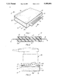
- FIG. 1 is a perspective view, of the conformable sanding assembly, according to the present invention.
- FIG. 2 is a cross-sectional view, of the conformable sanding assembly, taken along line 2--2, as seen in FIG. 1, illustrating the flexible attachment means which is incorporated within a compressible sanding block.
- FIG. 3 shows the conformable sanding assembly of the present invention attached to a schematized power or hand means for sanding, illustrating the flexible attachment means and its connection to the power or hand means for sanding.
- FIG. 4 is a sectional view, taken through another sanding assembly embodying the present invention, and showing the assembly in a detached position, relative to a conventional sanding machine.
- FIG. 5 is a sectional view, taken in the same direction as FIG. 4, but illustrating a further embodiment of the present invention.
- FIG. 1 is a perspective view of a conformable sanding device 10, embodying features of the present invention.
- the sanding block 18, here depicted as rectangular, comprises a compressible core 11, which is coated with a textured abrasive substance 12, on both major upper and lower flat faces 13 and 13A, respectively.
- the flexible attachment strap means 14, extends outward from and overhangs both the proximate and distal side edges of the sanding block 18. Enhanced orbital action is achieved by gripping the overhanging edges 16, of the flexible attachment means 14, which also enhance the rigidity of the sanding block 18.
- Compressibility of the block's core material 11 provides for sanding of non-planar surfaces with a plurality of angular, concave, or convex, contours and edges.
- the potential dual nature of the textured abrasive coating 12, allows the operator to turn the conformable sanding device easily, and use both faces 13 and 13A. This is done by simply turning the conformable sanding device, when one side is spent, or employing different types of abrasive on the major upper and lower faces, which are both readily accessible.
- the embodiment of the present invention as herein illustrated in FIG. 1, comprises a flexible strap attachment means 14, being disposed approximately equidistant between the major upper and lower flat faces 13 and 13A, of the sanding block 18.
- the major upper and lower faces, 13 and 13A are coated with a textured abrasive substance 12, along the entire surface areas.
- the flexible strap attachment means 14, of the preferred embodiment is from about 1/32 to about 1/16 of an inch thick.
- the flexible strap attachment means 14, extends outward from, and overhangs opposite side edges of the sanding block 18, by about 13/16 of an inch out of each of the ends of the sanding block 18, as depicted in the illustration of said embodiment in FIG. 1. As seen in FIG.
- the thickness dimension of block 18, is approximately the same as the projection distance of strap 14, i.e., about 13/16 of an inch.
- the block 18, thickness dimension is thus several times the thickness dimension of strap 14.
- the configuration and other dimensions of the sanding device may vary to suit the application, and sanding machine 20, to which the device may be attached by strap means 14.
- FIG. 2 is a cross-sectional view of the conformable sanding device 10, taken along line 2--2, as seen in FIG. 1, illustrating the flexible strap attachment means 14, incorporated within said sanding block 18.
- the sanding block 18 comprises a core of compressible elastic material 11, covered with a coating of abrasive substance 12, on both major faces 13 and 13A. Orbital action is enhanced by use of the overhanging edges 16, of the flexible strap attachment means 14, allowing the operator to grip said device and to turn it over to use both major upper and lower faces 13 and 13A, coated with a textured abrasive substance 12.
- the conformability of said sanding device 10, is further enhanced by a linear rectangular slot (not numbered), cut through the sanding block 18, which incorporates the flexible attachment means 14.
- This rectangular slot in the compressible core material 11, of the sanding block 18, allows the operator to apply pressure to either of the major upper and lower faces 13 and 13A, without sacrificing the angle formed between the surface being sanded and the major upper and lower faces 13 and 13A, making contact therewith.
- This feature also enables the operator to apply downward pressure while gripping the overhanging edges 16, of the flexible tongue-like attachment means 14, to force the flattened bottom surface 13, to conform to any number of angles, contours, or irregularly shaped non-planar surfaces.
- the flexible attachment means 14, therefore, serves these dual purposes for the present invention.
- FIG. 3 shows the conformable sanding assembly 10, attached to a schematized power or hand sanding machine 20, illustrating the flexible strap attachment means 14, and its connection to the power or hand sanding machine 20.
- the conformable sanding device 10 is coupled with said power sanding machine 20, by means of the overhanging edges 16, of the flexible attachment means 14.
- the overhanging edges 16, of the flexible strap attachment means 14, allow the power sanding means 20, to apply the necessary orbital or rotational force to the compressible sanding block 18. This feature provides substantial improvement over any disclosures heretofore available.
- said unique flexible attachment means 14, and overhanging edges 16, are designed for ready attachment and detachment of the conformable sanding assembly 10.
- This aspect of the current invention further provides for turning said sanding device as discussed above, when employed in conjunction with the power sanding machine 20.
- FIG. 4 illustrates another form of the present invention, used in conjunction with a conventional hand-guided orbital sanding machine 20.
- the sanding machine 20 includes a vibratable steel plate 22, having a relatively hard rubber pad 24, affixed to its flat lower face.
- the plate 22, and rubber pad 24, have a rectangular plan configuration.
- Plate 22 has a front end 26, and a rear end 28, spaced apart to define the length dimension of the plate 22.
- a sheet clamp means 30, is mounted on the upper surface of plate 22, at its front and rear ends, 26 and 28, respectively.
- Each clamp means 30, comprises a resilient steel spring arm 32, riveted, or otherwise affixed, at 34, to plate 22, and a curved clamp jaw 36, adapted to clamp a sheet of material, against the upper surface of plate 22.
- a crank member 37 is supported in spaced bearings 39, such that an offset central portion of the crank member 37, presses against the surface of the spring arm 32.
- a handle 40 extends right-angularly from one end of the crank member 37, whereby the crank member 37, can be rotated around its rotational axis, for raising or lowering its offset central portion.
- FIG. 4 shows each crank member 37, in its lowered position, whereby its offset central portion is pressing spring arm 32, downwardly, to its clamping position.
- FIG. 5 shows each crank member 37, in its raised position, wherein the offset portion of the crank arm 37, is lifted away from plate 22.
- the resilience of each spring arm 32 causes the spring arm 32, to be lifted to a point where its curved jaw 36, is spaced away from plate 22.
- Handle 40 is turned one-quarter turn, to move the spring arm 32, between its raised and lowered positions.
- the orbital sanding machine 20, depicted in FIGS. 4 and 5, is a conventional machine.
- the present invention concerns a conformable sanding assembly, usable with the conventional sanding machine.
- the sanding assembly comprises a rectangular block 42, formed of a foamed elastomeric material, e.g., foamed plastic or foamed rubber.
- the block 42 has a flat lower face 44, and a flat major upper face 45.
- the major faces have four connecting side edges 47, whereby, the block 42, has a rectangular plan configuration, that is substantially the same as that of steel plate 22.
- block 42 will have a length of about five (5) or six (6) inches, and a width of about four (4) or five (5) inches.
- the block 42 will have a thickness dimension 49, measuring at least three-quarters (3/4) of an inch.
- a sheet of abrasive material 50 is adhesively secured to the lower face 44 of the foam block 42.
- Sheet 50 entirely covers block major face 44, as well as the four (4) side edges 47, of the block 42.
- the sheet 50 is bent along straight lines at the block 42 corners, to conform to the block surfaces at 44 and 47.
- Sheet 50 can be a conventional sheet of sandpaper, or other suitable abrasive materials.
- fibrous sheet material is available under the tradename VELCRO.
- Hook and loop material sheet 55 has a back, or upper, surface that is coated with a film of pressure sensitive adhesive 57, whereby sheet 55 can be adhesively attached to the flat vibratable work surface of the orbital sanding machine 20.
- Sheet 55 has a length that is somewhat greater than the corresponding length of steel plate 22, and rubber pad 24, such that end portions 59, of sheet 55, can be extended around the ends of plate 22, and onto the plate 22 upper surface.
- Clamps 30, are actuable, to secure the ends of sheet 55 to the vibratable work member, i.e., plate 22 and rubber pad 24.
- the central areas of sheet 55, engaged with the lower face of rubber pad 24, is secured to the sanding machine work surface by means of the pressure sensitive adhesive film 57.
- the combination of clamps 30, and pressure sensitive adhesive film 57 ensures a non-slip, secure attachment of hook and loop sheet 55 to the vibratable work surface of the sanding machine 20.
- Hook and loop material sheet 53 is permanently bonded to relatively stiff panel 51, by way of any suitable adhesive, so that panel 53, becomes a permanent part of the sanding block.
- FIG. 4 shows the sanding block detached from the orbital sanding machine.
- the sanding block can be attached to the machine by moving the machine downwardly so that the fibers in the hook and loop sheet 55, interlock with the fibers in hook and loop sheet 53.
- the stiff panel 51 acts to prevent the sheets 53 and 55, from separating, i.e, panel 51, sufficiently rigidifies sheet 53, such that it is not possible to peel sheet 53 away from sheet 55, in stages.
- the hook and loop fibers in the two sheets, i.e, 53 and 55, are maintained in a common horizontal plane, such that all of the interlocked fibers act together to prevent the separation of sheet 53, from sheet 55.
- a very secure connection is thus provided between the sanding machine 20, and the sanding block 42.
- the foamed resilient block 42 can be deformed in response to the application of localized pressures thereon.
- the sanding apparatus can partially wrap around curved convex surfaces, or conform to concave surfaces.
- the foam block 42 returns to its predetermined configuration.
- the sanding assembly can thus be used to sand, or smooth, a variety of planar, and non-planar surfaces.
- FIG. 5 illustrates a variant of the apparatus depicted in FIG. 4, wherein a flexible sheet of hook and loop material 53a, is bonded directly to the upper major face 45, of the foam block 42.
- the foam block 42 has no stiffener panel similar to panel 51 of FIG. 4. End portions 61, of sheet 53a, extends beyond the side edges of foam block 42, for extension around the ends of plate 22 and pad 24.
- a second sheet of mating hook and loop material 55a has a film of pressure sensitive material 57, on its back surface, whereby the sheet can be detachably secured to the face of rubber pad 24, as shown in FIG. 5.
- FIG. 5 shows the sanding block 42, detached from the orbital sanding machine.
- the block 42 is attached to the machine by moving the machine downwardly, so that the fibers in the mating sheets of hook and loop material interlock.
- End portions 61, of sheet 53a are wrapped around the ends of plate 22, and fastened to the plate by clamps 30.
- the sanding block is securely fastened to the machine by the interlocked fibers in sheets 53a, and 55a, and by the clamps 30.
- Removal of the sanding block 42, from the machine 20, is accomplished by releasing clamps 30, so that end portions 61, of sheet 53a, can be unwrapped from the vibratable plate 22. Since the sanding block 42, does not have a stiffener panel, it is relatively flexible. The block 42, can be peeled away from sheet 53a, which remains on the machine 20.
- FIG. 5 shows the sanding block 42, in its detached condition.
- the present invention is concerned with the construction of the sanding block 42, and a hook and loop sheet, 55 or 55a, whereby the flexible, deformable block can be securely attached to a conventional sanding machine.
- the sanding assembly can be used for sanding planar, or non-planar surfaces.
Landscapes
- Engineering & Computer Science (AREA)
- Mechanical Engineering (AREA)
- Polishing Bodies And Polishing Tools (AREA)
Abstract
A conformable sanding assembly incorporating a flexible attachment for ready attachment to a hand or power sander. The sanding assembly is particularly useful for sanding contoured, and other non-planar surfaces and angles. The sanding assembly comprises a compressible sanding block said sanding block further comprising peripheral surfaces of an abrasive material and, said sanding block further comprising a flexible attachment. The flexible attachment is designed for ready attachment to, and ready removable detachment from, a hand or power sander.
Description
This is a Continuation-in-Part of our co-pending U.S. patent application Ser. No. 733,340, filed on Jul. 22, 1991 and now U.S. Pat. No. 5,220,752.
The present invention relates to sanding devices.
The present invention further relates to sanding devices incorporating attachment means.
The present invention also relates to conformable sanding devices, incorporating flexible attachment means, designed for ready attachment to, and ready removable detachment from, a hand or power sanding means.
It has been a long standing problem in the field of hand sanding means to create devices which possess appropriate stiffness values, enabling operators to apply even pressure and achieve evenly sanded finishes.
The present invention combines solutions to these problems by enhancing stiffness while simultaneously providing a unique flexible attachment means. However, a sanding device must also be sufficiently elastic, resilient and, in particular, conformable if all manner of surfaces, non-planar as well as planar, are to be sanded. It is necessary to provide a sanding device capable of withstanding forces and pressures applied to them, by their operators, without compromising the nature of the sanded finish achieved. To achieve these goals, the present invention employs a compressible medium and incorporates a unique attachment means, for attaching a compressible sanding block to an orbital sanding machine.
When employing a sanding device, unevenly applied pressure produces an uneven finish. Attempts have been made to enhance the stiffness of sanding devices, often at the expense of conformability. The present invention addresses this two-fold problem by adding an incorporated flexible attachment means. Additionally, previous disclosures fail to provide a means for one-hundred (100) percent coverage of all types of surfaces which require sanding, i.e., surfaces having curved, or non-planar contours.
The sanding assembly of the present invention has a conformability to rigidity ratio enabling the operator to sand all types of contours, curves, rounds, moldings, and other non-planar surfaces. Basically, the requisite stiffness is achieved by the rigidity supplied by the unique flexible attachment means. This component of the present invention allows the operator to apply pressure to the compressible sanding block without attendant deformation. However, the unique flexible attachment means does not detract from the elasticity inherent in the compressible core of the sanding block. This allows the operator to push the sanding block into a plurality of different angular applications, while maintaining the proper sanding angle. The incorporated flexible attachment means provides for this by enhancing the stiffness, yet allowing for adequate flexion. Therefore, with the present invention, simultaneous sanding of intersecting planar surfaces is possible, above and beyond all prior disclosures. A search of related art makes it apparent that these features have never before been combined as they are in the present invention.
Early disclosures divulge attempts such as a flexible sanding pad, only for manual use, providing nothing to enhance the rigidity or allow for ready attachment and detachment. Abrasive articles are known with means for attachment, but no account is taken of rigidity or flexibility. Other disclosures further divulge coated abrasive pads and pads of flexible foam, designed only to protect the tools edges during the use of the abrasive pads. Alternative disclosures include means of attaching a non-conformable sanding block to a power-driven tool by use of a magnetic mounting means. No combinations of previous disclosures contemplate the teachings of the present invention.
The present invention overcomes the prior art problems of inadequate rigidity, inadequate orbital action and lack of ready attachment and detachment, through incorporation of the unique flexible attachment means running through and extending outward from the sanding block. Nothing previously disclosed anticipates or contemplates these improvements.
It is an objective of the present invention to provide a conformable sanding assembly having a unique flexible attachment means incorporated within the compressible sanding block, for ready attachment to, and ready removable detachment from, a hand or power means for sanding.
Another objective is to provide a sanding device capable of sanding all manner and angle of contoured non-planar surfaces with enhanced rigidity and efficiency.
Still another objective is to provide a sanding device capable of quick detachment from the sanding means, and reversal of the sanding block, with subsequent re-attachment and ease of handling, resulting from the incorporated flexible attachment means.
The above and other objectives will become apparent in the description of the preferred embodiments.
A conformable sanding device for hand use or attachment to a power means for sanding, particularly useful for sanding contoured, non-planar surfaces and angles is described. The sanding device comprises a compressible sanding block coated on the major upper and lower peripheral surfaces with abrasive substance, and further comprises a unique flexible attachment means incorporated within the sanding block. The incorporated flexible attachment means is designed for ready attachment to, and ready removable detachment from, hand or power sander means.
In summary, and in accordance with the above discussion, the foregoing objectives are achieved in the following embodiments.
1. A conformable sanding assembly, comprising:
a block formed of a foamed elastomeric material;
said block having a predetermined shape, and being flexible and deformable, in response to the application of localized pressures thereon, but being elastically returnable to its predetermined shape, when such localized pressures are withdrawn;
said block having two parallel flat major faces, and four connecting side edges, extending between said flat faces;
said block having a thickness dimension normal to its flat major faces;
a sheet of abrasive material secured to one of the major faces of said block;
said abrasive sheet being coextensive with said one major face;
a stiff panel secured to the other major face of said block;
said stiff panel being coextensive with said other major face;
a first sheet of hook and loop attachment material bonded to said stiff panel;
a second mating sheet of hook and loop attachment material having a front fibrous surface adapted to detachably mate with said first sheet of hook and loop attachment material; and
said second mating sheet of hook and loop attachment material having a back surface, and a film of pressure-sensitive adhesive thereon, whereby said second sheet of hook and loop material can be adhesively attached to a flat movable work surface of an orbital sanding machine.
2. The sanding assembly, as described in paragraph 1, wherein the thickness dimension of said block is at least three-fourths (3/4) of an inch.
3. The sanding assembly, as described in paragraph 1, wherein:
the orbital sanding machine has a vibratable plate that forms the movable work surface;
said plate having a front end and a rear end, spaced apart to collectively define the length dimension of said plate;
a clamp means at each end of said plate; and
said second sheet of hook and loop material having a length dimension that is greater than the length dimension of the plate so that end portions of said second sheet are extendable around the plate ends for fastening by said clamp means.
4. The sanding assembly, as described in paragraph 1, wherein said sheet of abrasive material is bent at the limits of said one major face, so as to extend along the side edges of the block.
5. A conformable sanding assembly comprising:
a block, formed of a foamed elastomeric material;
said block having a predetermined shape, and being flexible and deformable in response to the application of localized pressures thereon, but being elastically returnable to its predetermined shape when such localized pressures are withdrawn;
said block having two parallel flat major faces and four connecting side edges extending between said flat faces;
said block having a thickness dimension normal to its flat major faces;
a sheet of abrasive material secured to one of the major faces of said block;
said abrasive sheet being coextensive with said one major face;
a first sheet of hook and loop attachment material bonded to the other major face of said block;
a second mating sheet of hook and loop attachment material having a front fibrous surface, adapted to detachably mate with said first sheet of attachment material;
said second mating sheet of hook and loop attachment material having a back surface, and a film of pressure sensitive adhesive thereon;
said sanding assembly being adapted for mounting on an orbital sanding machine that includes a vibratable plate having a front end and a rear end, spaced apart to collectively define the length dimension of the plate, and a clamp means at each end of said plate;
said first sheet of hook and loop material having a length dimension that is greater than the length dimension of the plate; and
whereby said second sheet of hook and loop material can be secured to the plate by pressing the adhesive film against the plate, while the end portions of said first sheet of hook and loop material are extended around the plate ends for fastening by said clamp means.
6. The sanding assembly, as described in paragraph 5, wherein the thickness dimension of said block is at least three-fourths (3/4) of an inch.
7. The sanding assembly, as described in paragraph 5, wherein said sheet abrasive material is bent at the limits of said one major face, so as to extend along the side edges of the block.
8. A conformable sanding assembly comprising:
a block formed of a foamed elastomeric material;
said block having a predetermined shape, and being flexible and deformable in response to the application of localized pressures thereon, but being elastically returnable to its predetermined shape, when such localized pressures are withdrawn;
said block having two parallel flat major faces and four connecting side edges extending between said flat faces;
said block having a thickness dimension normal to its flat major faces;
a sheet of abrasive material secured to one of the major faces of said block;
said abrasive sheet being coextensive with said one major face;
a first sheet of hook and loop attachment material;
means permanently attaching said first sheet of hook and loop material to the other major face of said block;
a second mating sheet of hook and loop attachment material having a front fibrous surface adapted to detachably mate with said first sheet of hook and loop material;
said second mating sheet of hook and loop material having a back surface, and a film of pressure-sensitive adhesive thereon; and
whereby said second sheet of hook and loop material can be adhesively attached to a flat movable work surface of an orbital sanding machine.
9. The sanding assembly, as described in paragraph 8, wherein the thickness dimension of said block is at least three quarters (3/4) of an inch.
10. The sanding assembly, as described in paragraph 8, wherein:
the orbital sanding machine has a vibratable plate that forms the movable work surface;
said plate having a front end and a rear end, spaced apart to collectively define the length dimension of the plate;
a clamp means at each end of said plate; and
one of said sheets of hook and loop material having a length dimension that is greater than the length dimension of the plate, so that end portions of said one sheet are extendable around the plate ends for fastening by said clamp means.
In order that the present invention may be more fully and readily understood, and, further, that all features thereof may be better appreciated, the present invention will now be described by way of preferred examples, with reference to the accompanying drawings.
FIG. 1, is a perspective view, of the conformable sanding assembly, according to the present invention.
FIG. 2, is a cross-sectional view, of the conformable sanding assembly, taken along line 2--2, as seen in FIG. 1, illustrating the flexible attachment means which is incorporated within a compressible sanding block.
FIG. 3, shows the conformable sanding assembly of the present invention attached to a schematized power or hand means for sanding, illustrating the flexible attachment means and its connection to the power or hand means for sanding.
FIG. 4, is a sectional view, taken through another sanding assembly embodying the present invention, and showing the assembly in a detached position, relative to a conventional sanding machine.
FIG. 5, is a sectional view, taken in the same direction as FIG. 4, but illustrating a further embodiment of the present invention.
FIG. 1, is a perspective view of a conformable sanding device 10, embodying features of the present invention. The sanding block 18, here depicted as rectangular, comprises a compressible core 11, which is coated with a textured abrasive substance 12, on both major upper and lower flat faces 13 and 13A, respectively. The flexible attachment strap means 14, extends outward from and overhangs both the proximate and distal side edges of the sanding block 18. Enhanced orbital action is achieved by gripping the overhanging edges 16, of the flexible attachment means 14, which also enhance the rigidity of the sanding block 18. Compressibility of the block's core material 11, provides for sanding of non-planar surfaces with a plurality of angular, concave, or convex, contours and edges. The potential dual nature of the textured abrasive coating 12, allows the operator to turn the conformable sanding device easily, and use both faces 13 and 13A. This is done by simply turning the conformable sanding device, when one side is spent, or employing different types of abrasive on the major upper and lower faces, which are both readily accessible.
The embodiment of the present invention, as herein illustrated in FIG. 1, comprises a flexible strap attachment means 14, being disposed approximately equidistant between the major upper and lower flat faces 13 and 13A, of the sanding block 18. The major upper and lower faces, 13 and 13A, are coated with a textured abrasive substance 12, along the entire surface areas. The flexible strap attachment means 14, of the preferred embodiment, is from about 1/32 to about 1/16 of an inch thick. The flexible strap attachment means 14, extends outward from, and overhangs opposite side edges of the sanding block 18, by about 13/16 of an inch out of each of the ends of the sanding block 18, as depicted in the illustration of said embodiment in FIG. 1. As seen in FIG. 2, the thickness dimension of block 18, is approximately the same as the projection distance of strap 14, i.e., about 13/16 of an inch. The block 18, thickness dimension is thus several times the thickness dimension of strap 14. The configuration and other dimensions of the sanding device may vary to suit the application, and sanding machine 20, to which the device may be attached by strap means 14.
FIG. 2, is a cross-sectional view of the conformable sanding device 10, taken along line 2--2, as seen in FIG. 1, illustrating the flexible strap attachment means 14, incorporated within said sanding block 18.
The sanding block 18, comprises a core of compressible elastic material 11, covered with a coating of abrasive substance 12, on both major faces 13 and 13A. Orbital action is enhanced by use of the overhanging edges 16, of the flexible strap attachment means 14, allowing the operator to grip said device and to turn it over to use both major upper and lower faces 13 and 13A, coated with a textured abrasive substance 12. The conformability of said sanding device 10, is further enhanced by a linear rectangular slot (not numbered), cut through the sanding block 18, which incorporates the flexible attachment means 14. This rectangular slot in the compressible core material 11, of the sanding block 18, allows the operator to apply pressure to either of the major upper and lower faces 13 and 13A, without sacrificing the angle formed between the surface being sanded and the major upper and lower faces 13 and 13A, making contact therewith. This feature also enables the operator to apply downward pressure while gripping the overhanging edges 16, of the flexible tongue-like attachment means 14, to force the flattened bottom surface 13, to conform to any number of angles, contours, or irregularly shaped non-planar surfaces. The flexible attachment means 14, therefore, serves these dual purposes for the present invention.
FIG. 3, shows the conformable sanding assembly 10, attached to a schematized power or hand sanding machine 20, illustrating the flexible strap attachment means 14, and its connection to the power or hand sanding machine 20.
The conformable sanding device 10, is coupled with said power sanding machine 20, by means of the overhanging edges 16, of the flexible attachment means 14. The overhanging edges 16, of the flexible strap attachment means 14, allow the power sanding means 20, to apply the necessary orbital or rotational force to the compressible sanding block 18. This feature provides substantial improvement over any disclosures heretofore available.
Having the compressible sanding block 18, attached to the power sanding machine 20, allows for the application of an appropriate degree of downward pressure to achieve a better sanding finish. This feature applies also to any hand uses of the conformable sanding device 10, as it permits the operator of the device to apply the requisite amount and degree of pressure with no danger of slippage or of creating an unevenly sanded finish through the application of uneven pressure. The overhanging edges 16, of the flexible attachment means 14, thus overcome yet another common problem in the sanding means field.
Additionally, said unique flexible attachment means 14, and overhanging edges 16, are designed for ready attachment and detachment of the conformable sanding assembly 10. This aspect of the current invention further provides for turning said sanding device as discussed above, when employed in conjunction with the power sanding machine 20.
FIG. 4, illustrates another form of the present invention, used in conjunction with a conventional hand-guided orbital sanding machine 20. The sanding machine 20, includes a vibratable steel plate 22, having a relatively hard rubber pad 24, affixed to its flat lower face. The plate 22, and rubber pad 24, have a rectangular plan configuration.
A crank member 37, is supported in spaced bearings 39, such that an offset central portion of the crank member 37, presses against the surface of the spring arm 32. A handle 40, extends right-angularly from one end of the crank member 37, whereby the crank member 37, can be rotated around its rotational axis, for raising or lowering its offset central portion. FIG. 4, shows each crank member 37, in its lowered position, whereby its offset central portion is pressing spring arm 32, downwardly, to its clamping position. FIG. 5, shows each crank member 37, in its raised position, wherein the offset portion of the crank arm 37, is lifted away from plate 22. The resilience of each spring arm 32, causes the spring arm 32, to be lifted to a point where its curved jaw 36, is spaced away from plate 22. Handle 40, is turned one-quarter turn, to move the spring arm 32, between its raised and lowered positions.
The orbital sanding machine 20, depicted in FIGS. 4 and 5, is a conventional machine. The present invention, as shown in FIG. 4, concerns a conformable sanding assembly, usable with the conventional sanding machine. The sanding assembly, comprises a rectangular block 42, formed of a foamed elastomeric material, e.g., foamed plastic or foamed rubber. The block 42, has a flat lower face 44, and a flat major upper face 45. The major faces have four connecting side edges 47, whereby, the block 42, has a rectangular plan configuration, that is substantially the same as that of steel plate 22. Typically, block 42, will have a length of about five (5) or six (6) inches, and a width of about four (4) or five (5) inches. The block 42, will have a thickness dimension 49, measuring at least three-quarters (3/4) of an inch.
A sheet of abrasive material 50, is adhesively secured to the lower face 44 of the foam block 42. Sheet 50, entirely covers block major face 44, as well as the four (4) side edges 47, of the block 42. Thus the sheet 50, is bent along straight lines at the block 42 corners, to conform to the block surfaces at 44 and 47. Sheet 50, can be a conventional sheet of sandpaper, or other suitable abrasive materials.
A relatively stiff panel 51, of plastic, or other non-flexible material, is bonded to the upper major face 45, of the foam block 42, to form a mounting surface for a sheet of fibrous hook and loop attachment material 53. Such fibrous sheet material is available under the tradename VELCRO. A second mating sheet of the fibrous hook and loop attachment material 55, is mounted on the lower face of rubber pad 24.
Hook and loop material sheet 55, has a back, or upper, surface that is coated with a film of pressure sensitive adhesive 57, whereby sheet 55 can be adhesively attached to the flat vibratable work surface of the orbital sanding machine 20. Sheet 55, has a length that is somewhat greater than the corresponding length of steel plate 22, and rubber pad 24, such that end portions 59, of sheet 55, can be extended around the ends of plate 22, and onto the plate 22 upper surface. Clamps 30, are actuable, to secure the ends of sheet 55 to the vibratable work member, i.e., plate 22 and rubber pad 24. The central areas of sheet 55, engaged with the lower face of rubber pad 24, is secured to the sanding machine work surface by means of the pressure sensitive adhesive film 57. The combination of clamps 30, and pressure sensitive adhesive film 57, ensures a non-slip, secure attachment of hook and loop sheet 55 to the vibratable work surface of the sanding machine 20.
Hook and loop material sheet 53, is permanently bonded to relatively stiff panel 51, by way of any suitable adhesive, so that panel 53, becomes a permanent part of the sanding block. FIG. 4, shows the sanding block detached from the orbital sanding machine. The sanding block can be attached to the machine by moving the machine downwardly so that the fibers in the hook and loop sheet 55, interlock with the fibers in hook and loop sheet 53. When the fibers are thus interlocked, the stiff panel 51, acts to prevent the sheets 53 and 55, from separating, i.e, panel 51, sufficiently rigidifies sheet 53, such that it is not possible to peel sheet 53 away from sheet 55, in stages. The hook and loop fibers in the two sheets, i.e, 53 and 55, are maintained in a common horizontal plane, such that all of the interlocked fibers act together to prevent the separation of sheet 53, from sheet 55. A very secure connection is thus provided between the sanding machine 20, and the sanding block 42.
Separation of the sanding block 42, from the sanding machine 20, requires that clamps 30, be unlocked, as shown in FIG. 5. With the clamps 30, unlocked, the end portions 59, of sheet 55, can be drawn away from steel plate 22, so as to permit the adhesive film 57, to be separated from the lower face of pad 24. After sheet 55, has been separated from pad 24, it can be peeled away from sheet 53, since sheet 55, then is in a flexible, non-rigid state.
During use of the machine for sanding purposes the foamed resilient block 42, can be deformed in response to the application of localized pressures thereon. The sanding apparatus can partially wrap around curved convex surfaces, or conform to concave surfaces. When the localized pressure is withdrawn, the foam block 42, returns to its predetermined configuration. The sanding assembly can thus be used to sand, or smooth, a variety of planar, and non-planar surfaces.
FIG. 5, illustrates a variant of the apparatus depicted in FIG. 4, wherein a flexible sheet of hook and loop material 53a, is bonded directly to the upper major face 45, of the foam block 42. The foam block 42, has no stiffener panel similar to panel 51 of FIG. 4. End portions 61, of sheet 53a, extends beyond the side edges of foam block 42, for extension around the ends of plate 22 and pad 24.
A second sheet of mating hook and loop material 55a, has a film of pressure sensitive material 57, on its back surface, whereby the sheet can be detachably secured to the face of rubber pad 24, as shown in FIG. 5.
FIG. 5, shows the sanding block 42, detached from the orbital sanding machine. The block 42, is attached to the machine by moving the machine downwardly, so that the fibers in the mating sheets of hook and loop material interlock. End portions 61, of sheet 53a, are wrapped around the ends of plate 22, and fastened to the plate by clamps 30. The sanding block is securely fastened to the machine by the interlocked fibers in sheets 53a, and 55a, and by the clamps 30.
Removal of the sanding block 42, from the machine 20, is accomplished by releasing clamps 30, so that end portions 61, of sheet 53a, can be unwrapped from the vibratable plate 22. Since the sanding block 42, does not have a stiffener panel, it is relatively flexible. The block 42, can be peeled away from sheet 53a, which remains on the machine 20. FIG. 5, shows the sanding block 42, in its detached condition.
The present invention is concerned with the construction of the sanding block 42, and a hook and loop sheet, 55 or 55a, whereby the flexible, deformable block can be securely attached to a conventional sanding machine. The sanding assembly can be used for sanding planar, or non-planar surfaces.
The previous detailed description of the preferred embodiments of the present invention is presented for purposes of clarity of understanding only, and no unnecessary limitations should be understood or implied therefrom, as all appropriate mechanical and functional equivalents to the above, which may be obvious to those skilled in the arts pertaining thereto, are considered to be encompassed within the claims of this invention.
Claims (10)
1. A conformable sanding assembly, comprising:
a block formed of a foamed elastomeric material;
said block having a predetermined shape, and being flexible and deformable, in response to the application of localized pressures thereon, but being elastically returnable to its predetermined shape, when such localized pressures are withdrawn;
said block having two parallel flat major faces, and four connecting side edges, extending between said flat faces;
said block having a thickness dimension normal to its flat major faces;
a sheet of abrasive material secured to one of the major faces of said block;
said abrasive sheet being coextensive with said one major face;
a stiff panel secured to the other major face of said block;
said stiff panel being coextensive with said other major face;
a first sheet of hook and loop attachment material bonded to said stiff panel;
a second mating sheet of hook and loop attachment material having a front fibrous surface adapted to detachably mate with said first sheet of hook and loop attachment material; and
said second mating sheet of hook and loop attachment material having a back surface, and a film of pressure-sensitive adhesive thereon, whereby said second sheet of hook and loop material can be adhesively attached to a flat movable work surface of an orbital sanding machine.
2. The sanding assembly, as described in claim 1, wherein the thickness dimension of said block is at least three-fourths (3/4) of an inch.
3. The sanding assembly, as described in claim 1, wherein:
the orbital sanding machine has a vibratable plate that forms the movable work surface;
said plate having a front end and a rear end, spaced apart to collectively define the length dimension of said plate;
a clamp means at each end of said plate; and
said second sheet of hook and loop material having a length dimension that is greater than the length dimension of the plate so that end portions of said second sheet are extendable around the plate ends for fastening by said clamp means.
4. The sanding assembly, as described in claim 1, wherein said sheet of abrasive material is bent at the limits of said one major face, so as to extend along the side edges of the block.
5. A conformable sanding assembly comprising:
a block, formed of a foamed elastomeric material;
said block having a predetermined shape, and being flexible and deformable in response to the application of localized pressures thereon, but being elastically returnable to its predetermined shape when such localized pressures are withdrawn;
said block having two parallel flat major faces and four connecting side edges extending between said flat faces;
said block having a thickness dimension normal to its flat major faces;
a sheet of abrasive material secured to one of the major faces of said block;
said abrasive sheet being coextensive with said one major face;
a first sheet of hook and loop attachment material bonded to the other major face of said block;
a second mating sheet of hook and loop attachment material having a front fibrous surface, adapted to detachably mate with said first sheet of attachment material;
said second mating sheet of hook and loop attachment material having a back surface, and a film of pressure sensitive adhesive thereon;
said sanding assembly being adapted for mounting on an orbital sanding machine that includes a vibratable plate having a front end and a rear end, spaced apart to collectively define the length dimension of the plate, and a clamp means at each end of said plate;
said first sheet of hook and loop material having a length dimension that is greater than the length dimension of the plate; and
whereby said second sheet of hook and loop material can be secured to the plate by pressing the adhesive film against the plate, while the end portions of said first sheet of hook and loop material are extended around the plate ends for fastening by said clamp means.
6. The sanding assembly, as described in claim 5, wherein the thickness dimension of said block is at least three-fourths (3/4) of an inch.
7. The sanding assembly, as described in claim 5, wherein said sheet abrasive material is bent at the limits of said one major face, so as to extend along the side edges of the block.
8. A conformable sanding assembly comprising:
a block formed of a foamed elastomeric material;
said block having a predetermined shape, and being flexible and deformable in response to the application of localized pressures thereon, but being elastically returnable to its predetermined shape, when such localized pressures are withdrawn;
said block having two parallel flat major faces and four connecting side edges extending between said flat faces;
said block having a thickness dimension normal to its flat major faces;
a sheet of abrasive material secured to one of the major faces of said block;
said abrasive sheet being coextensive with said one major face;
a first sheet of hook and loop attachment material;
means permanently attaching said first sheet of hook and loop material to the other major face of said block;
a second mating sheet of hook and loop attachment material having a front fibrous surface adapted to detachably mate with said first sheet of hook and loop material;
said second mating sheet of hook and loop material having a back surface, and a film of pressure-sensitive adhesive thereon; and
whereby said second sheet of hook and loop material can be adhesively attached to a flat movable work surface of an orbital sanding machine.
9. The sanding assembly, as described in claim 8, wherein the thickness dimension of said block is at least three quarters (3/4) of an inch.
10. The sanding assembly, as described in claim 8, wherein:
the orbital sanding machine has a vibratable plate that forms the movable work surface;
said plate having a front end and a rear end, spaced apart to collectively define the length dimension of the plate;
a clamp means at each end of said plate; and
one of said sheets of hook and loop material having a length dimension that is greater than the length dimension of the plate, so that end portions of said one sheet are extendable around the plate ends for fastening by said clamp means.
Priority Applications (1)
| Application Number | Priority Date | Filing Date | Title |
|---|---|---|---|
| US08/080,002 US5309681A (en) | 1991-07-22 | 1993-06-21 | Conformable sanding assembly |
Applications Claiming Priority (3)
| Application Number | Priority Date | Filing Date | Title |
|---|---|---|---|
| US07/733,340 US5220752A (en) | 1991-07-22 | 1991-07-22 | Conformable sanding device incorporating a flexible attachment means |
| EP93303402A EP0635335A1 (en) | 1991-07-22 | 1993-04-30 | A conformable sanding device incorporating a flexible attachment means |
| US08/080,002 US5309681A (en) | 1991-07-22 | 1993-06-21 | Conformable sanding assembly |
Related Parent Applications (1)
| Application Number | Title | Priority Date | Filing Date |
|---|---|---|---|
| US07/733,340 Continuation-In-Part US5220752A (en) | 1991-07-22 | 1991-07-22 | Conformable sanding device incorporating a flexible attachment means |
Publications (1)
| Publication Number | Publication Date |
|---|---|
| US5309681A true US5309681A (en) | 1994-05-10 |
Family
ID=26134285
Family Applications (2)
| Application Number | Title | Priority Date | Filing Date |
|---|---|---|---|
| US07/733,340 Expired - Fee Related US5220752A (en) | 1991-07-22 | 1991-07-22 | Conformable sanding device incorporating a flexible attachment means |
| US08/080,002 Expired - Fee Related US5309681A (en) | 1991-07-22 | 1993-06-21 | Conformable sanding assembly |
Family Applications Before (1)
| Application Number | Title | Priority Date | Filing Date |
|---|---|---|---|
| US07/733,340 Expired - Fee Related US5220752A (en) | 1991-07-22 | 1991-07-22 | Conformable sanding device incorporating a flexible attachment means |
Country Status (2)
| Country | Link |
|---|---|
| US (2) | US5220752A (en) |
| EP (1) | EP0635335A1 (en) |
Cited By (42)
| Publication number | Priority date | Publication date | Assignee | Title |
|---|---|---|---|---|
| US5383309A (en) * | 1992-07-09 | 1995-01-24 | Norton Company | Abrasive tool |
| WO1996021536A1 (en) * | 1995-01-09 | 1996-07-18 | Dahlgren William R | Method for attaching and stabilizing material during machining operations |
| US5607345A (en) * | 1994-01-13 | 1997-03-04 | Minnesota Mining And Manufacturing Company | Abrading apparatus |
| US5634843A (en) * | 1995-01-17 | 1997-06-03 | Liu; Te-Hsi | Multi-functional grinding wiper |
| US5810650A (en) * | 1995-12-29 | 1998-09-22 | Joest; Peter | Grinding member and an adapter for mounting the grinding member on a grinding machine or a grinding member holder |
| US5840089A (en) | 1994-01-13 | 1998-11-24 | Minnesota Mining And Manufacturing Company | Method of making an abrasive article |
| US6081959A (en) * | 1996-07-01 | 2000-07-04 | Umbrell; Richard | Buffer centering system |
| US6105197A (en) * | 1998-04-14 | 2000-08-22 | Umbrell; Richard T. | Centering system for buffing pad |
| US6227959B1 (en) * | 1997-06-16 | 2001-05-08 | Donald W. Beaudry | Sanding sponge |
| US6298518B1 (en) | 1998-04-14 | 2001-10-09 | Richard T. Umbrell | Heat dissipating buffing pad |
| US6325708B1 (en) * | 2000-09-28 | 2001-12-04 | Jody W. Miles | Device for sanding a drywall corner |
| US6524175B2 (en) | 1997-06-16 | 2003-02-25 | Donald W. Beaudry | Sanding sponge |
| US6579162B2 (en) | 1994-01-13 | 2003-06-17 | 3M Innovative Properties Company | Abrasive article |
| US6626746B2 (en) * | 2000-09-18 | 2003-09-30 | Hilti Aktiengesellschaft | Sander with a clamping device |
| US6659852B1 (en) | 2002-08-05 | 2003-12-09 | Brad R. Wettstein | Sanding block |
| US20040182409A1 (en) * | 2002-02-27 | 2004-09-23 | Easytrim Llc (A Delaware Limited Liability Company) | Method and apparatus for improved nail trimming |
| USD497092S1 (en) | 2002-08-26 | 2004-10-12 | 3M Innovative Properties Company | Corner sanding sponge |
| US20050059329A1 (en) * | 1994-10-11 | 2005-03-17 | 3M Innovative Properties Company | Abrasive materials |
| US20050272359A1 (en) * | 2004-06-03 | 2005-12-08 | Pontieri James M | Sanding rope and applications thereof |
| US20060053576A1 (en) * | 2004-09-10 | 2006-03-16 | Mclain Scott S | Buffing pad with graded flexibility and replaceable working face |
| US7040973B1 (en) * | 2003-09-10 | 2006-05-09 | William Kitts | Abrasive sheet |
| US20060135049A1 (en) * | 2004-12-16 | 2006-06-22 | Petersen John G | Millwork sanding sponge |
| USD527974S1 (en) | 2004-12-16 | 2006-09-12 | 3M Innovative Properties Company | Millwork sanding sponge |
| US20070072524A1 (en) * | 2002-08-05 | 2007-03-29 | James Hassler | Sanding block |
| US20070077875A1 (en) * | 2004-06-03 | 2007-04-05 | Pontieri James M | Sanding rope and applications thereof |
| US20070135029A1 (en) * | 2005-12-09 | 2007-06-14 | Field Craig M | Drywall sander |
| US20070212993A1 (en) * | 2006-03-09 | 2007-09-13 | Annis Kent V | Tool for working on a surface |
| US20080176494A1 (en) * | 2007-01-19 | 2008-07-24 | Simon Palushaj | Abrasive preparation device with an improved abrasion element assembly |
| US20090104864A1 (en) * | 2007-10-17 | 2009-04-23 | Full Circle International, Inc. | Tool for working on a surface |
| US20090239455A1 (en) * | 2008-03-24 | 2009-09-24 | Credo Technology Corporation | Contour sanding pad |
| US7621802B2 (en) | 2002-08-26 | 2009-11-24 | 3M Innovative Properties Company | Corner sanding sponge |
| US20100009609A1 (en) * | 2008-07-10 | 2010-01-14 | 3M Innovative Properties Company | Conversion assemblage adaptable for use in combination with a surface modifying apparatus and method thereof |
| US20100009606A1 (en) * | 2008-07-10 | 2010-01-14 | 3M Innovative Properties Company | Conversion assemblage adaptable for use in combination with a surface modifying apparatus and method thereof |
| US20100009607A1 (en) * | 2008-07-10 | 2010-01-14 | 3M Innovative Properties Company | Conversion assemblage adaptable for use in combination with a surface modifying apparatus and method thereof |
| US20100124873A1 (en) * | 2008-11-18 | 2010-05-20 | Lake Country Manufacturing, Inc. | Multi-Faceted Sanding/Finishing Tool |
| US8117709B2 (en) | 2004-09-10 | 2012-02-21 | Lake Country Manufacturing, Inc. | Buffing system including load absorbing fixture with multiple compression load deflection and replaceable working face |
| US8696413B2 (en) | 2011-09-16 | 2014-04-15 | Shelwes, Llc | Contouring sanding device |
| US20150283677A1 (en) * | 2014-04-08 | 2015-10-08 | Qci Global Inc. | Grinder system with replaceable clay embedded disc |
| WO2018003767A1 (en) * | 2016-06-30 | 2018-01-04 | キョーラク株式会社 | Cushion pad and robot arm using same |
| US20180071880A1 (en) * | 2015-03-24 | 2018-03-15 | Aros S.R.L. | Tool for polishing and/or lapping stone material surfaces |
| WO2023180865A1 (en) * | 2022-03-22 | 2023-09-28 | 3M Innovative Properties Company | Abrasive article attachment systems and methods |
| US12296432B2 (en) | 2019-08-19 | 2025-05-13 | Diamabrush Llc | Floor polishing apparatus |
Families Citing this family (6)
| Publication number | Priority date | Publication date | Assignee | Title |
|---|---|---|---|---|
| GB9420509D0 (en) * | 1994-10-11 | 1994-11-23 | Minnesota Mining & Mfg | Abrasive materials |
| WO1996034721A2 (en) * | 1995-05-04 | 1996-11-07 | Alice Schlattl | Device for grinding surfaces |
| WO1999051402A1 (en) * | 1998-04-03 | 1999-10-14 | John William Collins | Sanding apparatus |
| US7186174B1 (en) | 2005-05-09 | 2007-03-06 | Alfred W Arnold | Sanding block holder |
| ITCR20090028A1 (en) * | 2009-07-22 | 2011-01-23 | Paolo Corazzi Fibre Srl | INTERCHANGEABLE CLEANING DEVICE |
| US20120220207A1 (en) * | 2011-02-24 | 2012-08-30 | Dean Daniel R | Substrate preparation tool system and method |
Citations (15)
| Publication number | Priority date | Publication date | Assignee | Title |
|---|---|---|---|---|
| US3089294A (en) * | 1959-12-23 | 1963-05-14 | Vermont American Corp | Abrasive article |
| US3129540A (en) * | 1961-11-27 | 1964-04-21 | Fred G Valles | Flexible sanding block |
| US3540160A (en) * | 1967-01-31 | 1970-11-17 | Antonio De Rose | Surface finishing device |
| US4263755A (en) * | 1979-10-12 | 1981-04-28 | Jack Globus | Abrasive product |
| US4558542A (en) * | 1978-05-05 | 1985-12-17 | Miska Marton | Stick-on abrasive disc |
| US4617767A (en) * | 1985-01-14 | 1986-10-21 | Ali Frank F | Sanding, buffing and polishing tool and parts thereof |
| FR2620367A1 (en) * | 1987-09-16 | 1989-03-17 | Poly Eclat Sa | Manual polishing pad |
| EP0351273A1 (en) * | 1988-07-08 | 1990-01-17 | Premines S.A. | Sanding bloc |
| US5007128A (en) * | 1989-01-18 | 1991-04-16 | Minnesota Mining And Manufacturing Company | Compounding, glazing or polishing pad |
| US5022189A (en) * | 1990-03-12 | 1991-06-11 | Saul Earl W | Sander extension device |
| US5025596A (en) * | 1988-09-13 | 1991-06-25 | Minnesota Mining And Manufacturing Company | Hand scouring pad |
| US5054245A (en) * | 1990-07-25 | 1991-10-08 | The Butcher Company | Combination of cleaning pads, cleaning pad mounting members and a base member for a rotary cleaning machine |
| US5123139A (en) * | 1991-01-16 | 1992-06-23 | Meguiar's, Inc. | Buffing pad assembly |
| US5170595A (en) * | 1990-12-19 | 1992-12-15 | Wiand Ronald C | Pull tab for velcro backed marble grinding pad and method for removal |
| US5201785A (en) * | 1991-05-10 | 1993-04-13 | Minnesota Mining & Manufacturing Company | Disc-holder assembly |
Family Cites Families (6)
| Publication number | Priority date | Publication date | Assignee | Title |
|---|---|---|---|---|
| GB260829A (en) * | 1926-02-22 | 1926-11-11 | Adolph Kunke Hillson | Improvements relating to hand blocks for use in supporting sheets of abrasive or polishing material |
| US3085372A (en) * | 1961-10-12 | 1963-04-16 | Harold L Sweeney | Cleaning pads |
| US4459987A (en) * | 1982-03-10 | 1984-07-17 | William W. Haefliger | Flexible abrasive pad |
| US4714644A (en) * | 1986-12-30 | 1987-12-22 | Minnesota Mining And Manufacturing Company | Sanding pad |
| DE3725656A1 (en) * | 1987-08-03 | 1989-02-16 | Festo Kg | Sanding or polishing tool - has elastomeric cushion to enable abrasive surface to conform to curved surfaces |
| DE3843515A1 (en) * | 1988-12-23 | 1990-06-28 | Festo Kg | Portable orbital sander (oscillating grinder, superfinish device) |
-
1991
- 1991-07-22 US US07/733,340 patent/US5220752A/en not_active Expired - Fee Related
-
1993
- 1993-04-30 EP EP93303402A patent/EP0635335A1/en not_active Withdrawn
- 1993-06-21 US US08/080,002 patent/US5309681A/en not_active Expired - Fee Related
Patent Citations (16)
| Publication number | Priority date | Publication date | Assignee | Title |
|---|---|---|---|---|
| US3089294A (en) * | 1959-12-23 | 1963-05-14 | Vermont American Corp | Abrasive article |
| US3129540A (en) * | 1961-11-27 | 1964-04-21 | Fred G Valles | Flexible sanding block |
| US3540160A (en) * | 1967-01-31 | 1970-11-17 | Antonio De Rose | Surface finishing device |
| US4558542A (en) * | 1978-05-05 | 1985-12-17 | Miska Marton | Stick-on abrasive disc |
| US4263755A (en) * | 1979-10-12 | 1981-04-28 | Jack Globus | Abrasive product |
| US4617767A (en) * | 1985-01-14 | 1986-10-21 | Ali Frank F | Sanding, buffing and polishing tool and parts thereof |
| FR2620367A1 (en) * | 1987-09-16 | 1989-03-17 | Poly Eclat Sa | Manual polishing pad |
| EP0351273A1 (en) * | 1988-07-08 | 1990-01-17 | Premines S.A. | Sanding bloc |
| US5025596A (en) * | 1988-09-13 | 1991-06-25 | Minnesota Mining And Manufacturing Company | Hand scouring pad |
| US5007128A (en) * | 1989-01-18 | 1991-04-16 | Minnesota Mining And Manufacturing Company | Compounding, glazing or polishing pad |
| US5007128B1 (en) * | 1989-01-18 | 1993-12-07 | Minnesota Mining And Manufacturing Company | Compounding,glazing or polishing pad |
| US5022189A (en) * | 1990-03-12 | 1991-06-11 | Saul Earl W | Sander extension device |
| US5054245A (en) * | 1990-07-25 | 1991-10-08 | The Butcher Company | Combination of cleaning pads, cleaning pad mounting members and a base member for a rotary cleaning machine |
| US5170595A (en) * | 1990-12-19 | 1992-12-15 | Wiand Ronald C | Pull tab for velcro backed marble grinding pad and method for removal |
| US5123139A (en) * | 1991-01-16 | 1992-06-23 | Meguiar's, Inc. | Buffing pad assembly |
| US5201785A (en) * | 1991-05-10 | 1993-04-13 | Minnesota Mining & Manufacturing Company | Disc-holder assembly |
Cited By (66)
| Publication number | Priority date | Publication date | Assignee | Title |
|---|---|---|---|---|
| US5383309A (en) * | 1992-07-09 | 1995-01-24 | Norton Company | Abrasive tool |
| US6884157B2 (en) | 1994-01-13 | 2005-04-26 | 3M Innovative Properties Company | Abrasive article |
| US5607345A (en) * | 1994-01-13 | 1997-03-04 | Minnesota Mining And Manufacturing Company | Abrading apparatus |
| US6579161B1 (en) | 1994-01-13 | 2003-06-17 | 3M Innovative Properties Company | Abrasive article |
| US6579162B2 (en) | 1994-01-13 | 2003-06-17 | 3M Innovative Properties Company | Abrasive article |
| US5840089A (en) | 1994-01-13 | 1998-11-24 | Minnesota Mining And Manufacturing Company | Method of making an abrasive article |
| US7044834B2 (en) | 1994-01-13 | 2006-05-16 | 3M Innovative Properties Company | Abrasive article |
| US20050202770A1 (en) * | 1994-01-13 | 2005-09-15 | 3M Innovative Properties | Abrasive article |
| US20050059329A1 (en) * | 1994-10-11 | 2005-03-17 | 3M Innovative Properties Company | Abrasive materials |
| US7311591B2 (en) | 1994-10-11 | 2007-12-25 | 3M Innovative Properties Company | Abrasive materials |
| WO1996021536A1 (en) * | 1995-01-09 | 1996-07-18 | Dahlgren William R | Method for attaching and stabilizing material during machining operations |
| US5634843A (en) * | 1995-01-17 | 1997-06-03 | Liu; Te-Hsi | Multi-functional grinding wiper |
| US5810650A (en) * | 1995-12-29 | 1998-09-22 | Joest; Peter | Grinding member and an adapter for mounting the grinding member on a grinding machine or a grinding member holder |
| US6081959A (en) * | 1996-07-01 | 2000-07-04 | Umbrell; Richard | Buffer centering system |
| US6227959B1 (en) * | 1997-06-16 | 2001-05-08 | Donald W. Beaudry | Sanding sponge |
| US6524175B2 (en) | 1997-06-16 | 2003-02-25 | Donald W. Beaudry | Sanding sponge |
| US6298518B1 (en) | 1998-04-14 | 2001-10-09 | Richard T. Umbrell | Heat dissipating buffing pad |
| US6105197A (en) * | 1998-04-14 | 2000-08-22 | Umbrell; Richard T. | Centering system for buffing pad |
| US6626746B2 (en) * | 2000-09-18 | 2003-09-30 | Hilti Aktiengesellschaft | Sander with a clamping device |
| WO2002026442A1 (en) * | 2000-09-28 | 2002-04-04 | Jody Miles | Device for sanding a drywall corner |
| US6325708B1 (en) * | 2000-09-28 | 2001-12-04 | Jody W. Miles | Device for sanding a drywall corner |
| US20040182409A1 (en) * | 2002-02-27 | 2004-09-23 | Easytrim Llc (A Delaware Limited Liability Company) | Method and apparatus for improved nail trimming |
| US7188628B2 (en) * | 2002-02-27 | 2007-03-13 | Shubert Lawrence G | Fingernail trimmer having rotationally oscillating abrasive surface |
| US20070072524A1 (en) * | 2002-08-05 | 2007-03-29 | James Hassler | Sanding block |
| US20110171892A1 (en) * | 2002-08-05 | 2011-07-14 | Brad R. Wettstein | Sanding Block |
| US6659852B1 (en) | 2002-08-05 | 2003-12-09 | Brad R. Wettstein | Sanding block |
| US7780506B2 (en) | 2002-08-05 | 2010-08-24 | Brad R. Wettstein | Sanding block |
| USD497092S1 (en) | 2002-08-26 | 2004-10-12 | 3M Innovative Properties Company | Corner sanding sponge |
| US7621802B2 (en) | 2002-08-26 | 2009-11-24 | 3M Innovative Properties Company | Corner sanding sponge |
| US7040973B1 (en) * | 2003-09-10 | 2006-05-09 | William Kitts | Abrasive sheet |
| US7297049B2 (en) | 2004-06-03 | 2007-11-20 | Pontieri James M | Sanding rope and applications thereof |
| US20050272359A1 (en) * | 2004-06-03 | 2005-12-08 | Pontieri James M | Sanding rope and applications thereof |
| US7144314B2 (en) | 2004-06-03 | 2006-12-05 | Pontieri James M | Sanding rope and applications thereof |
| US20070077875A1 (en) * | 2004-06-03 | 2007-04-05 | Pontieri James M | Sanding rope and applications thereof |
| US6997794B2 (en) | 2004-06-03 | 2006-02-14 | James Matthew Pontieri | Sanding rope and method of forming same |
| US20050272361A1 (en) * | 2004-06-03 | 2005-12-08 | Pontieri James M | Sanding rope and method of forming same |
| US8117709B2 (en) | 2004-09-10 | 2012-02-21 | Lake Country Manufacturing, Inc. | Buffing system including load absorbing fixture with multiple compression load deflection and replaceable working face |
| US20060053576A1 (en) * | 2004-09-10 | 2006-03-16 | Mclain Scott S | Buffing pad with graded flexibility and replaceable working face |
| USD527974S1 (en) | 2004-12-16 | 2006-09-12 | 3M Innovative Properties Company | Millwork sanding sponge |
| US20060135049A1 (en) * | 2004-12-16 | 2006-06-22 | Petersen John G | Millwork sanding sponge |
| US20070135029A1 (en) * | 2005-12-09 | 2007-06-14 | Field Craig M | Drywall sander |
| US7497765B2 (en) | 2005-12-09 | 2009-03-03 | Ec Sander, L.L.C. | Drywall sander |
| US7867064B2 (en) | 2005-12-09 | 2011-01-11 | Ec Sander, L.L.C. | Drywall sander |
| US20070212993A1 (en) * | 2006-03-09 | 2007-09-13 | Annis Kent V | Tool for working on a surface |
| US7670210B2 (en) | 2006-03-09 | 2010-03-02 | Full Circle International, Inc. | Tool for working on a surface |
| US8043144B2 (en) | 2007-01-19 | 2011-10-25 | Epoxi Tech, Inc. | Abrasive preparation device with an improved abrasion element assembly |
| US7690970B2 (en) * | 2007-01-19 | 2010-04-06 | Epoxy-Tech, Inc. | Abrasive preparation device with an improved abrasion element assembly |
| US20100203814A1 (en) * | 2007-01-19 | 2010-08-12 | Simon Palushaj | Abrasive preparation device with an improved abrasion element assembly |
| US20080176494A1 (en) * | 2007-01-19 | 2008-07-24 | Simon Palushaj | Abrasive preparation device with an improved abrasion element assembly |
| US7927192B2 (en) | 2007-10-17 | 2011-04-19 | Full Circle International, Inc | Tool for working on a surface |
| US20090104864A1 (en) * | 2007-10-17 | 2009-04-23 | Full Circle International, Inc. | Tool for working on a surface |
| US8210909B2 (en) | 2008-03-24 | 2012-07-03 | Robert Bosch Gmbh | Abrading system |
| US20090239455A1 (en) * | 2008-03-24 | 2009-09-24 | Credo Technology Corporation | Contour sanding pad |
| US8469775B2 (en) * | 2008-07-10 | 2013-06-25 | 3M Innovative Properties Company | Conversion assemblage adaptable for use in combination with a surface modifying apparatus and method thereof |
| US20100009606A1 (en) * | 2008-07-10 | 2010-01-14 | 3M Innovative Properties Company | Conversion assemblage adaptable for use in combination with a surface modifying apparatus and method thereof |
| US20100009609A1 (en) * | 2008-07-10 | 2010-01-14 | 3M Innovative Properties Company | Conversion assemblage adaptable for use in combination with a surface modifying apparatus and method thereof |
| US20100009607A1 (en) * | 2008-07-10 | 2010-01-14 | 3M Innovative Properties Company | Conversion assemblage adaptable for use in combination with a surface modifying apparatus and method thereof |
| US8210910B2 (en) * | 2008-11-18 | 2012-07-03 | Lake Country Manufacturing, Inc. | Multi-faceted sanding/finishing tool |
| US20100124873A1 (en) * | 2008-11-18 | 2010-05-20 | Lake Country Manufacturing, Inc. | Multi-Faceted Sanding/Finishing Tool |
| US8696413B2 (en) | 2011-09-16 | 2014-04-15 | Shelwes, Llc | Contouring sanding device |
| US20150283677A1 (en) * | 2014-04-08 | 2015-10-08 | Qci Global Inc. | Grinder system with replaceable clay embedded disc |
| US20180071880A1 (en) * | 2015-03-24 | 2018-03-15 | Aros S.R.L. | Tool for polishing and/or lapping stone material surfaces |
| WO2018003767A1 (en) * | 2016-06-30 | 2018-01-04 | キョーラク株式会社 | Cushion pad and robot arm using same |
| JP2018001328A (en) * | 2016-06-30 | 2018-01-11 | キョーラク株式会社 | Cushion pad and robot arm using the same |
| US12296432B2 (en) | 2019-08-19 | 2025-05-13 | Diamabrush Llc | Floor polishing apparatus |
| WO2023180865A1 (en) * | 2022-03-22 | 2023-09-28 | 3M Innovative Properties Company | Abrasive article attachment systems and methods |
Also Published As
| Publication number | Publication date |
|---|---|
| US5220752A (en) | 1993-06-22 |
| EP0635335A1 (en) | 1995-01-25 |
Similar Documents
| Publication | Publication Date | Title |
|---|---|---|
| US5309681A (en) | Conformable sanding assembly | |
| CA2435855C (en) | Sanding sponge | |
| US4202139A (en) | Conformable hand sanding pad | |
| US5054248A (en) | Four-way hand sander | |
| US4516360A (en) | Molded pole-type sandpapering tool having resilient paper retention means | |
| US6227959B1 (en) | Sanding sponge | |
| US2711059A (en) | Universal sander | |
| US20060154582A1 (en) | Abrasive holder | |
| JP2582934Y2 (en) | Polishing equipment | |
| US6165060A (en) | Sanding apparatus | |
| US6116999A (en) | Sander for a bullnose cornerbead and method of use | |
| US8210909B2 (en) | Abrading system | |
| US20020009966A1 (en) | Sanding gloves | |
| US3900976A (en) | Device for supporting a coated abrasive | |
| US6042462A (en) | Flexible backing for abrasive material in sheets | |
| CN210757248U (en) | Antiskid sand plate device | |
| JPH0750141Y2 (en) | Polishing tool | |
| RU98118007A (en) | DEVICE FOR FASTENING THE ABRASIVE TOOL ON THE GRINDING SHAFT | |
| JPH0344453Y2 (en) | ||
| JPH071246Y2 (en) | Desk sander | |
| JP3072542U (en) | Nabe polish | |
| JP3969794B2 (en) | Polishing buff | |
| KR200393886Y1 (en) | Backup plate for sandpaper | |
| KR0123957Y1 (en) | Sandpaper Base | |
| AU2004233524B2 (en) | Abrasive holder |
Legal Events
| Date | Code | Title | Description |
|---|---|---|---|
| FPAY | Fee payment |
Year of fee payment: 4 |
|
| SULP | Surcharge for late payment | ||
| FPAY | Fee payment |
Year of fee payment: 8 |
|
| REMI | Maintenance fee reminder mailed | ||
| REMI | Maintenance fee reminder mailed | ||
| LAPS | Lapse for failure to pay maintenance fees | ||
| FP | Lapsed due to failure to pay maintenance fee |
Effective date: 20060510 |
|
| STCH | Information on status: patent discontinuation |
Free format text: PATENT EXPIRED DUE TO NONPAYMENT OF MAINTENANCE FEES UNDER 37 CFR 1.362 |