US529920A - Gottfried f - Google Patents
Gottfried f Download PDFInfo
- Publication number
- US529920A US529920A US529920DA US529920A US 529920 A US529920 A US 529920A US 529920D A US529920D A US 529920DA US 529920 A US529920 A US 529920A
- Authority
- US
- United States
- Prior art keywords
- car
- spring
- cable
- circuit controller
- circuit
- Prior art date
- Legal status (The legal status is an assumption and is not a legal conclusion. Google has not performed a legal analysis and makes no representation as to the accuracy of the status listed.)
- Expired - Lifetime
Links
- 229910052698 phosphorus Inorganic materials 0.000 description 8
- 239000004020 conductor Substances 0.000 description 4
- 238000010276 construction Methods 0.000 description 4
- 229910052739 hydrogen Inorganic materials 0.000 description 4
- 230000011664 signaling Effects 0.000 description 4
- 210000003414 Extremities Anatomy 0.000 description 2
- 206010022114 Injury Diseases 0.000 description 2
- 229910052799 carbon Inorganic materials 0.000 description 2
- 230000001934 delay Effects 0.000 description 2
- 239000002184 metal Substances 0.000 description 2
- 229910052757 nitrogen Inorganic materials 0.000 description 2
- 229910052760 oxygen Inorganic materials 0.000 description 2
- 230000000284 resting Effects 0.000 description 2
- 230000000717 retained Effects 0.000 description 2
Images
Classifications
-
- B—PERFORMING OPERATIONS; TRANSPORTING
- B61—RAILWAYS
- B61B—RAILWAY SYSTEMS; EQUIPMENT THEREFOR NOT OTHERWISE PROVIDED FOR
- B61B12/00—Component parts, details or accessories not provided for in groups B61B7/00 - B61B11/00
- B61B12/06—Safety devices or measures against cable fracture
Definitions
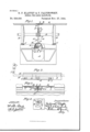
- Figure 1 is a transverse section through the road-bed of a cable railway, a portion of a car being represented in position on the rails.
- Fig. 2 is a detail side view of a portion of one wall of the conduit, the signaling devices being represented diagrammatically.
- Fig. 3 is a detail section on the line ww of Fig. 1, the direction of sight being downward and a portion of the road-bed and wall of the conduit being broken away.
- Fig. at is a plan view of a portion of the floor of the car.
- the conduit A covered in at the top by the metal walls B and B, between the upper edges of which the slot b is formed, and the road-bed represented by the rails O, C, may be constructed and arranged in any usual or preferred manner.
- the car also may be of any ordinary construction and in Fig. l of the drawings a single axle D with its wheels E, E, and a portion of the truck frame, indi cated at F are shown with a portion of the floor Got a car above them.
- electrical conductors H and H which form the two members of a circuit which includes a battery I and an electric signal J which is represented for convenience by an ordinary electric bell.
- the conductors are preferably insulated and at suitable intervals through their length provision is made whereby the circuit may be completed from one to the other from a moving car and the signal J thereby caused to indicate to the engineer at the power house that the cable must be stopped instantly.
- the circuit controller as represented at K, may be of ordinary construction, comprising a fixed contact Is and a spring contact is which is normally separated from the contact 7c but may be made to complete the circuit by pressure thereon. Provision is made whereby this circuit controller may be operated at will from a passing car and the arrangement which is suitable for the purpose will now be described.
- a long fiat spring L which may be rigidly secured at one end of the wall B, as at I, while at the other end it isfree to move more or less, being retained in proper position by a bolt Z which passes through a slot Z in the spring into the wall B. It will be observed that the spring L- curves outward gradually from the wall B and may be pressed inward by some part moving with the car without injury, the
- the circuit controller K may be actuated the instant that pressure begins to be applied upon the spring L and that the spring itself may be of such form as to permit a long contact with the moving part we prefer to provide a secondary spring M inside of the first spring L and resting always against the movable part 70 of the circuit controller.
- This secondary spring M may be fixed directly to the spring L or, as represented, it may be secured at one end with the spring L to the wall 13 and at the other end may rest against the spring L.
- the part which moves with the car and is adapted to press upon the spring L should be so arranged that it shall normally pass by the spring L without contact with any one of them but may be set from the car itself so as to make contact with the springs L as the car passes. It is also desirable that this part should be supported by the truck frame of the car so that it may not move up or down with the body of the car while at the same time it shall be capable of being set from above the floor of the car.
- a short vertical shaft N is supported in a suitable bearing in the truck frame F and bears at its lower end an arm or arms 02, n, which stand normally in 'the same plane with the grip and consequently out of contact with the springs L.
- the arms n, n are of such length, however, that when the shaft N is given a quarter turn one arm or the other, as the case may be, shall be in position to strike the springs L, L, and press them to one side and thereby close the circuit between the parts 70 and 713' of the circuit controller K.
- the shaft N is coupled at its upper end by a universal joint 0 to a telescopic shaft P, P, one member-I of which has a pin or lug p which engages a longitudinal slot 19' in the other member.
- the one member P extends through the floor G of the car and at its upper end is suitably formed so that it may be rotated. As represented in Figs.
- the section P has pivoted upon its extremity a handle Q which may be laid down flat in one recess or another of a recessed plate R which is set in the fioor of the car.
- a handle Q which may be laid down flat in one recess or another of a recessed plate R which is set in the fioor of the car.
- the arrangement above described permits the arms a, n, to move always in the same horizontal plane without interference from the oscillations of the car body, while at the same time the arms n, '27., may be set from within the car or from above the floor thereof whenever required.
Description
(NoModelJ G. P. KLAFFKY & P. FALTINOWSKY. SIGNALFOR GABLB RAILWAYS.
No. 529,920. Patented Nov. 27, 1894..
NITED STATES PATENT OFFICE.
GOTTFRIED F. KLAFFKY AND FRANK FALTINOWSKY, OF NEiV YORK, N. Y.
SIGNAL FOR CABLE RAILWA YS.
SPECIFICATION forming part of Letters Patent No. 529,920, dated November 27, 1894.
Application filed May 8, 1894- Scrial No. 510,466. (No model.)
To aZZ whom it may concern.-
Be it known that we, GOTTFRIED F. KLAFF- KY and FRANK FALTINOWSKY, of the city, county, and State of New York, have invented certain new and useful Improvements in Signals for Cable Railways; and we do hereby declare that the following is a full and exact description thereof, reference being had to the accompanying drawings, and to theletters of reference marked thereon, making a part of this specification.
In the operation of cable railways in which the cable moves in an underground conduit it occasionally happens that the grip, by which connection is established between the cable and the'car, becomes entangled with a broken and loosened strand or wire of the cable so that it is impossible to release the car from the cable without stopping the cable. To do this it is necessary to communicate with the engineer at the power house for which purpose reliance is sometimes placed upon the ordinary telephone system and sometimes upon a special telegraphic or telephonic system with which connection can be made at stations located at intervals along the line of the railway. There is always, however, more or less delay in communicating with the engineer by the usual methods as some one upon the street must be advised of the trouble by some one on the car or some one must leave the car at considerable risk. Such delays are fruitful sources of danger in crowded streets and it therefore becomes desirable to provide some means whereby the engineer may be warned of the necessity of stopping the cable from any car at any point on the line and it is the object of this invention to provide such means which shall be thoroughly efficient and always reliable and at the same time shall involve little expense in their application to existing structures.
The features of our invention will be pointed out more particularly hereinafter.
In the accompanying drawings: Figure 1 is a transverse section through the road-bed of a cable railway, a portion of a car being represented in position on the rails. Fig. 2 is a detail side view of a portion of one wall of the conduit, the signaling devices being represented diagrammatically. Fig. 3 is a detail section on the line ww of Fig. 1, the direction of sight being downward and a portion of the road-bed and wall of the conduit being broken away. Fig. at is a plan view of a portion of the floor of the car.
The conduit A, covered in at the top by the metal walls B and B, between the upper edges of which the slot b is formed, and the road-bed represented by the rails O, C, may be constructed and arranged in any usual or preferred manner. The car also may be of any ordinary construction and in Fig. l of the drawings a single axle D with its wheels E, E, and a portion of the truck frame, indi cated at F are shown with a portion of the floor Got a car above them. These several parts are represented merely to enable the application of the invention. to be understood, the invention itself being independent of any particular form or arrangement thereof.
In any convenient part of the conduit are supported electrical conductors H and H which form the two members of a circuit which includes a battery I and an electric signal J which is represented for convenience by an ordinary electric bell. The conductors are preferably insulated and at suitable intervals through their length provision is made whereby the circuit may be completed from one to the other from a moving car and the signal J thereby caused to indicate to the engineer at the power house that the cable must be stopped instantly. The circuit controller, as represented at K, may be of ordinary construction, comprising a fixed contact Is and a spring contact is which is normally separated from the contact 7c but may be made to complete the circuit by pressure thereon. Provision is made whereby this circuit controller may be operated at will from a passing car and the arrangement which is suitable for the purpose will now be described.
In the same horizontal plane with the circuit controller K and covering the same is a long fiat spring L which may be rigidly secured at one end of the wall B, as at I, while at the other end it isfree to move more or less, being retained in proper position by a bolt Z which passes through a slot Z in the spring into the wall B. It will be observed that the spring L- curves outward gradually from the wall B and may be pressed inward by some part moving with the car without injury, the
efiect of pressure being to complete the circuit through the circuit controller K, while the length of the spring and its freedom for moving at one end in the direction of movement of the car insure a sufficiently long closing of the circuit to actuate the signal J without fail. In order that the circuit controller K may be actuated the instant that pressure begins to be applied upon the spring L and that the spring itself may be of such form as to permit a long contact with the moving part we prefer to provide a secondary spring M inside of the first spring L and resting always against the movable part 70 of the circuit controller. This secondary spring M may be fixed directly to the spring L or, as represented, it may be secured at one end with the spring L to the wall 13 and at the other end may rest against the spring L. The part which moves with the car and is adapted to press upon the spring L should be so arranged that it shall normally pass by the spring L without contact with any one of them but may be set from the car itself so as to make contact with the springs L as the car passes. It is also desirable that this part should be supported by the truck frame of the car so that it may not move up or down with the body of the car while at the same time it shall be capable of being set from above the floor of the car. We have represented a simple and convenient device for this purpose. A short vertical shaft N is supported in a suitable bearing in the truck frame F and bears at its lower end an arm or arms 02, n, which stand normally in 'the same plane with the grip and consequently out of contact with the springs L. The arms n, n, are of such length, however, that when the shaft N is given a quarter turn one arm or the other, as the case may be, shall be in position to strike the springs L, L, and press them to one side and thereby close the circuit between the parts 70 and 713' of the circuit controller K. The shaft N is coupled at its upper end by a universal joint 0 to a telescopic shaft P, P, one member-I of which has a pin or lug p which engages a longitudinal slot 19' in the other member. The one member P extends through the floor G of the car and at its upper end is suitably formed so that it may be rotated. As represented in Figs. 1 and 4: the section P has pivoted upon its extremity a handle Q which may be laid down flat in one recess or another of a recessed plate R which is set in the fioor of the car. The arrangement above described permits the arms a, n, to move always in the same horizontal plane without interference from the oscillations of the car body, while at the same time the arms n, '27., may be set from within the car or from above the floor thereof whenever required.
The operation of our device will be readily understood from the foregoing description. WVhenever the grip becomes entangled with the cable or whenever from any other cause it is necessary that the cable be stopped the handle Q is raised from the recess in which it lies and is given a quarter turn with the shaft P, P, N, thereby setting the arms n, n, in the position represented by dotted lines in Figs. 1 and 3. Then, as the car continues its movement one or the other of the arms 1%, n, will strike the springs L and will press upon them to cause them in turn to operate the circuit controller K covered by each one and thereby to actuate the signaling device in the power house.
"We claim as our invention- 1. In a railway, the combination with a conduit and an electric circuitincludinga signal and a circuit controller fixed within the circuit, of a fiat spring covering said circuit controller, and means carried by the car and adapted to be set from the car to press upon said spring and operate said circuit controller, substantially as shown and described.
2. In a railway, the combination with a conduit and an electric circuit including a signal and a circuit controller fixed within the conduit, of a fiat spring covering said circuit controller, a secondary spring between the first spring and the circuit controller and in contact with both, substantially as shown and described.
3. In a railway, the combination with a conduit, a car, and an electric circuit including a signal and a circuit controller, of a vertical shaft mounted in a bearing on the truck frame and having an arm to operate the circuit controller, anda second shaft having a bearing in the car body and coupled to the first shaft to permit oscillation of the car body withoutinterference with the first shaft, substantially as shown and described.
In testimony whereof we have signed our names to this specification in the presence of two subscribing witnesses.
GOTTFRIED F. KLAFFKY. V FRANK FALTINOVVSKY.
\Vitnesses:
A. N. JESBERA, A. WIDDER.
Publications (1)
| Publication Number | Publication Date |
|---|---|
| US529920A true US529920A (en) | 1894-11-27 |
Family
ID=2598701
Family Applications (1)
| Application Number | Title | Priority Date | Filing Date |
|---|---|---|---|
| US529920D Expired - Lifetime US529920A (en) | Gottfried f |
Country Status (1)
| Country | Link |
|---|---|
| US (1) | US529920A (en) |
-
0
- US US529920D patent/US529920A/en not_active Expired - Lifetime
Similar Documents
| Publication | Publication Date | Title |
|---|---|---|
| US536923A (en) | Safety device for electric railways having sectional conductors | |
| US529920A (en) | Gottfried f | |
| US566398A (en) | Mechanism for operating car couplings | |
| US1052268A (en) | Current-collecting means for signal apparatus or the like. | |
| US778343A (en) | Automatic train-stopping system. | |
| US775529A (en) | Electrically-operated railway-track switch. | |
| US767140A (en) | Train-signal. | |
| US500937A (en) | Conduit railway insulator | |
| US492265A (en) | Conduit electric railway | |
| US446546A (en) | Electric eailway signal | |
| US495193A (en) | Arthur w | |
| US727478A (en) | Electric switch. | |
| US380647A (en) | de mier | |
| US232344A (en) | Oscar gassett and iseael fisher | |
| US427042A (en) | Electrical train-signal | |
| US848507A (en) | Underground electric railway. | |
| US1038832A (en) | Railway-telephone. | |
| US445634A (en) | Edward m | |
| US277569A (en) | Railway telegraphic signal | |
| US560071A (en) | Railway-signal | |
| US354460A (en) | Railway-signal | |
| US530828A (en) | Barre | |
| US751900A (en) | Trolley road-crossing | |
| US628299A (en) | Apparatus for signaling upon railways. | |
| US876387A (en) | Brake-setting apparatus for railways. |