US5297481A - System for compacting and storing separately recyclable and nonrecyclable waste materials - Google Patents
System for compacting and storing separately recyclable and nonrecyclable waste materials Download PDFInfo
- Publication number
- US5297481A US5297481A US07/929,218 US92921892A US5297481A US 5297481 A US5297481 A US 5297481A US 92921892 A US92921892 A US 92921892A US 5297481 A US5297481 A US 5297481A
- Authority
- US
- United States
- Prior art keywords
- storage compartment
- waste storage
- waste
- platform
- support member
- Prior art date
- Legal status (The legal status is an assumption and is not a legal conclusion. Google has not performed a legal analysis and makes no representation as to the accuracy of the status listed.)
- Expired - Fee Related
Links
Images


Classifications
-
- B—PERFORMING OPERATIONS; TRANSPORTING
- B30—PRESSES
- B30B—PRESSES IN GENERAL
- B30B9/00—Presses specially adapted for particular purposes
- B30B9/30—Presses specially adapted for particular purposes for baling; Compression boxes therefor
- B30B9/3092—Presses specially adapted for particular purposes for baling; Compression boxes therefor with two or more stationary press boxes co-operating alternately with a press ram or simultaneously with press rams
-
- B—PERFORMING OPERATIONS; TRANSPORTING
- B09—DISPOSAL OF SOLID WASTE; RECLAMATION OF CONTAMINATED SOIL
- B09B—DISPOSAL OF SOLID WASTE NOT OTHERWISE PROVIDED FOR
- B09B3/00—Destroying solid waste or transforming solid waste into something useful or harmless
- B09B3/30—Destroying solid waste or transforming solid waste into something useful or harmless involving mechanical treatment
- B09B3/32—Compressing or compacting
-
- B—PERFORMING OPERATIONS; TRANSPORTING
- B30—PRESSES
- B30B—PRESSES IN GENERAL
- B30B9/00—Presses specially adapted for particular purposes
- B30B9/30—Presses specially adapted for particular purposes for baling; Compression boxes therefor
- B30B9/3003—Details
-
- Y—GENERAL TAGGING OF NEW TECHNOLOGICAL DEVELOPMENTS; GENERAL TAGGING OF CROSS-SECTIONAL TECHNOLOGIES SPANNING OVER SEVERAL SECTIONS OF THE IPC; TECHNICAL SUBJECTS COVERED BY FORMER USPC CROSS-REFERENCE ART COLLECTIONS [XRACs] AND DIGESTS
- Y10—TECHNICAL SUBJECTS COVERED BY FORMER USPC
- Y10S—TECHNICAL SUBJECTS COVERED BY FORMER USPC CROSS-REFERENCE ART COLLECTIONS [XRACs] AND DIGESTS
- Y10S220/00—Receptacles
- Y10S220/908—Trash container
- Y10S220/909—Segregated
Definitions
- the present invention is directed to devices for storing and compacting waste materials. More specifically, a preferred embodiment of the present invention is directed to a system including two separate compacting and storage units and a support rack for storing one storage and compacting unit on top of the other thereby minimizing the floor space occupied by the two units.
- the present invention is directed to overcoming the disadvantages of the prior art recited above as well as achieving advantages neither disclosed nor contemplated by the prior art which are discussed hereinafter.
- An object of the present invention is to overcome the disadvantages of prior known systems for storing and compacting separately recyclable and nonrecyclable waste materials.
- Another object of the present invention is to provide a system for compacting and storing separately recyclable and nonrecyclable waste materials which eliminate the possibility of contamination of the recyclable waste materials.
- a further object of the present invention is to provide a system for storing and compacting recyclable and nonrecyclable waste materials which takes up minimal floor space and provides maximum storage capacity.
- Yet a further object of the present invention is to provide a system for storing and compacting recyclable waste material wherein an operator can insert either type of material from the same loading platform.
- Still a further object of the present invention is to provide a system having a rack structure which supports and houses two separate storage and compacting units in the floor space of just over one storage and compacting unit.
- Yet still a further object of the present invention is to provide a system having a rack structure for supporting and housing two separate storage and compacting units while permitting each of the compacting and storage units to be readily placed on a conventional transport vehicle.
- the present invention is directed to a system for compacting and storing separately recyclable and nonrecyclable waste materials.
- the system includes two separate storage and compacting units, one of which is designated for the storage of recyclable material and the other designated for the storage of nonrecyclable material.
- the system further includes a support rack having a horizontally extending platform and a plurality of vertical support legs extending downwardly from the horizontally extending platform. The vertical legs and horizontal platform form a passageway or channel for receiving at least a portion of one storage and compacting unit.
- the other storage and compacting unit is mounted on the horizontally extending platform of the support rack, directly above the first compacting and storage unit.
- FIG. 1 is a side elevational view of a first preferred embodiment of the present invention.
- FIG. 2 is a right end elevational view of the preferred embodiment illustrated in FIG. 1.
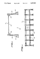
- FIG. 3 is a right end elevational view of a support rack formed in accordance with the first preferred embodiment of the present invention.
- FIG. 4 is a side elevational view of the support rack depicted in FIG. 3.
- FIG. 5 is a side elevational view of a second preferred embodiment of the present invention.
- FIG. 6 is a right end elevational view of the second preferred embodiment depicted in FIG. 5.
- the recycling system A includes a first storage and compacting unit B, a second storage and compacting unit C, a support rack D and a loading platform E.
- the first storage and compacting unit B includes a storage container 2 and a compactor 4.
- the storage container 2 and compactor 4 are integrally connected and mounted on a single roll-on/roll-off skid 6 having rollers or wheelers 8 and 10 at each end thereof.
- the skid 6 permits the first storage and compacting unit B to be rolled on and off the support rack D.
- the storage container 2 is of conventional construction and has an octagon shaped cross-section. An opening is formed in the lower left end of the of the storage container 2 to permit receipt of the waste material from compacting unit 4. Further, a large exit opening is formed in the right end of storage container 2.
- the exit opening is sealed by a door 12 (see FIG. 2) having a sealing member extending around the outer periphery thereof.
- the storage container 2 forms a single large storage compartment for receiving either recyclable or nonrecyclable waste material.
- storage container 2 may be provided with a plurality of partitions, if desired, so that the storage container can accommodate different classes or subclasses of waste materials.
- the compactor 4 preferably includes a single ram 13 actuated by a single piston and cylinder assembly 15, as seen in dotted lines in FIG. 1. Other ram and piston and cylinder assemblies may be employed.
- the upper surface of compactor 4 has an opening formed therein adjacent chute or hopper 14 so that waste material may be readily dispensed into the compactor 4.
- the ram 13 is movable between a storage position (shown in FIG. 1) and an operating position. In the storage position, the ram 13 is disposed rearward of the opening in the upper surface of compactor 4.
- the front face 17 of the ram and the side walls of the compactor 4 form a charging chamber for receiving waste materials from chute 14.
- the piston and cylinder assembly 15 is operated by conventional hydraulic drives. However, it will be readily appreciated that other drives including pneumatic drives may be used.
- the ram 13 advances towards the storage container 2 thereby directing the waste material in the charging chamber into the storage container 2.
- a closure plate 16 is operably connected to the chute 14. More specifically, the closure plate 16 is connected at hinge 18 to chute 14. As is readily evident from FIG. 1, the closure plate 16 is counter-balanced in that it extends beyond hinge 18 in the direction of storage container 2 and is sufficiently weighted such that upon lifting the closure plate 16 to gain access to the chute 14, the plate 16 will remain in the open position until closed by an operator.
- the first storage and compacting unit B is mounted on the support rack structure D.
- the support rack structure D includes a horizontally extending platform 20.
- Platform 20 is supported above the ground by a plurality of side support legs 22.
- An angle support 24 extends outwardly from the base of each support leg 22 to provide the support rack D with greater stability.
- a channel or cross-bar 26 (see FIGS. 1 and 4) is provided on each side of support rack D and interconnects the side legs 22 providing the same with greater stability.
- a substantially triangularly shaped support member 28 extends inwardly from each of the side legs 22 adjacent the uppermost portion thereof and are secured to the underside of platform 20 (see FIG. 3).
- the platform 20 and side legs 22 form a passageway or channel 30 for receiving the second storage and compacting unit C.
- the second storage and compacting unit C includes a storage container 32, a compactor 34 and a roll-on/roll-off skid 36.
- the storage container 32 and compactor 34 are integrally connected to each other and mounted on skid 36.
- Skid 36 includes rollers or wheels 38 and 40 at each end thereof permitting the second storage container and compacting unit C to be rolled under or out from the support rack D.
- the storage container 32 includes a single large storage area.
- storage container 32 may be modified in a similar manner as proposed with respect to storage container 2.
- the compactor 34 is positioned rearwardly of the platform 20 of rack D. Further, the upper surface of compactor 34 has an opening formed therein adjacent hopper or chute 42 for permitting waste material to be readily dispensed into the compactor 34.
- Compactor 34 has a similar ram and piston and cylinder assembly to that of compactor 4.
- an operator can dispense waste material in compactor 4 (through chute 14) or compactor 34 (through chute 42) from the same loading platform E. It will be appreciated that an opening is formed in the loading platform E about the uppermost portion 44 of the chute 42 to permit the operator to dispense waste material therein.
- a pivotable closure plate or security is provided to close the opening formed adjacent area 44 of chute 42.
- the uppermost portions of the side walls of storage container 32 are angled complementary to the support members 28 so that the unit C can be readily positioned under or removed from passageway or channel 30 formed by support rack D.
- unit C is designated for storing nonrecyclable material while unit B is designated for storing recyclable material.
- unit B is designated for storing recyclable material.
- conventional transport vehicles are dispatched to the location of storage system A to transport the storage units B and C to a disposal site. More specifically, to remove unit B from rack D a transport vehicle backs up to the storage system A.
- the horizontal platform 20 of rack D is positioned at substantially the same height as the bed of a conventional transport vehicle. This height is approximately fifty inches. Therefore, the unit B can be rolled directly onto the bed of the transport vehicle.
- the transport vehicle includes a winch and the unit B includes a pull-out bar 46 to receive the hook of the winch.
- the unit B is rolled right onto the bed of the transport vehicle.
- a somewhat different procedure must be followed to remove unit C and place it on the bed of a conventional transport vehicle.
- the unit C includes a pull-out bar 48 similar to pull-out bar 46 of unit B.
- the hook of the winch engages the pull-out bar 48 and, once actuated the winch rolls the unit C out from underneath the support rack D.
- the transport vehicle's bed is positioned at an incline so that the storage unit C can be rolled thereon as is customarily done.
- the recycling system A permits the storage of recyclable and nonrecyclable materials with complete integrity maintained between the recyclable and nonrecyclable waste materials. This is accomplished by providing two totally separate storage and compacting units. Moreover, the recycling system A greatly enhances the storage capacity of the proprietor thereby reducing the frequency at which the storage system must be empty. Moreover, the increased storage capacity is achieved with only a minimal amount of increase in the floor space occupied by the storage system A.
- Storage system F includes a first storage and compacting unit G, a second storage and compacting unit H, a support rack I and a loading platform J.
- the first storage and compacting unit G includes a storage container 50 and a compactor 52.
- Compactor 52 is stationary and detachably connected to storage container 50 via conventional couplers 54.
- the storage container 50 preferably has a single large storage area formed therein. However, it will be readily appreciated that partitions (horizontally or vertically oriented) can be provided within container 50 to compartmentalize the same.
- the storage container has a single large opening formed at the left end thereof.
- a single door 56 closes off the large opening. However, a smaller opening is formed in door 56 to permit waste material to pass from the compactor 52 to the storage container 50.
- the compactor 52 has an opening formed in the upper surface thereof. The opening is formed in the upper surface of the compactor 52 forward of the conveyor 58 positioned above the compactor 52. As seen in FIGS. 5 and 6, only storage container 50 is mounted on roll-on/roll-off skid 53. Skid 53 includes a pull-out bar (see FIG. 6).
- a single ram 57 is housed in compactor 52 and is operated by a single piston and cylinder assembly 59 similar to that depicted in FIG. 1.
- the ram 57 is movable between an operating and a storage position. In the storage position (shown in FIG. 5), the ram 57 is positioned rearwardly of the opening in the upper surface of compactor 52. Thus, the front face 61 of the ram and the side walls of the compactor form a charging chamber for receiving waste material.
- the piston and cylinder assembly 59 is actuated by a hydraulic drive (not shown). However, it will be readily appreciated that other drives such as pneumatic drives may be employed.
- Wall 60 of loading platform J includes an opening passing therethrough positioned adjacent conveyor 58.
- a pivotal closure plate or security door 62 seals off the opening in the wall 60 adjacent conveyor 58. It will be readily appreciated that an operator need merely lift closure plate 62 and put waste material on the conveyor 58 to dispense the waste material into the compactor 52.
- the conveyor 58 is actuated by a conventional drive to advance the waste material placed thereon to the opening in compactor 52.
- the support rack I is of the exact same construction as rack D and therefore will not be described in detail.
- the storage unit H is very similar to the storage unit C disclosed in the first preferred embodiment. More specifically, unit H includes a storage container 64 and an integrally connected compactor 66 mounted on a roll-on/roll-off skid 68.
- the skid 68 includes rollers 70 and 72 disposed at opposite ends thereof.
- the skid 68 further includes a pull-out bar 74 positioned at the right end thereof.
- the storage container 64 includes a single large storage area. However, by providing partitions, the storage container H may be compartmentalized, if desired.
- a door 76 and corresponding seal seals off the exit opening formed in the right end of the storage container 64. As is seen in FIG. 6, the uppermost portions of the side walls of storage container 64 are angled complementary to the support members 28 so that the unit H may be readily removed from underneath the rack I.
- the compactor 66 includes a single ram operably connected to a single piston and cylinder assembly of the type used in compactor 52.
- the compactor 66 has an opening formed in the upper surface thereof adjacent hopper 78.
- a chute 80 is operably connected at one end to hopper 78 and at the other end to an opening formed in wall 60 of loading platform J.
- a closure plate or security door 82 seals off the opening formed in wall 60 adjacent chute 80.
- storage units G and H are transported by a conventional transport vehicle to a disposal site in a very similar manner to storage units B and C of the first preferred embodiment.
- compactor 52 is uncoupled from storage container 50 prior to storage container 50 (only) being removed by a conventional transport vehicle.
Landscapes
- Engineering & Computer Science (AREA)
- Mechanical Engineering (AREA)
- Environmental & Geological Engineering (AREA)
- Refuse Collection And Transfer (AREA)
Abstract
Description
Claims (17)
Priority Applications (1)
| Application Number | Priority Date | Filing Date | Title |
|---|---|---|---|
| US07/929,218 US5297481A (en) | 1992-08-13 | 1992-08-13 | System for compacting and storing separately recyclable and nonrecyclable waste materials |
Applications Claiming Priority (1)
| Application Number | Priority Date | Filing Date | Title |
|---|---|---|---|
| US07/929,218 US5297481A (en) | 1992-08-13 | 1992-08-13 | System for compacting and storing separately recyclable and nonrecyclable waste materials |
Publications (1)
| Publication Number | Publication Date |
|---|---|
| US5297481A true US5297481A (en) | 1994-03-29 |
Family
ID=25457501
Family Applications (1)
| Application Number | Title | Priority Date | Filing Date |
|---|---|---|---|
| US07/929,218 Expired - Fee Related US5297481A (en) | 1992-08-13 | 1992-08-13 | System for compacting and storing separately recyclable and nonrecyclable waste materials |
Country Status (1)
| Country | Link |
|---|---|
| US (1) | US5297481A (en) |
Cited By (9)
| Publication number | Priority date | Publication date | Assignee | Title |
|---|---|---|---|---|
| US5622468A (en) * | 1992-10-30 | 1997-04-22 | Robin S.A. | Disposal facility for loading objects into a container |
| US6152672A (en) * | 1999-04-01 | 2000-11-28 | Alson; William B. | Segregated hazardous waste container system |
| US6468019B1 (en) | 2001-08-09 | 2002-10-22 | Joe Duval | Apparatus for use with waste compactor/baler machines |
| US20060042197A1 (en) * | 2004-05-03 | 2006-03-02 | Jody Langston | Apparatus, system, and method for condensing, separating and storing recyclable material |
| US20060157434A1 (en) * | 2005-01-19 | 2006-07-20 | Siemag Gmbh | Pallet-type conveyor system for hot metal-strip coils |
| US20100287896A1 (en) * | 2008-01-29 | 2010-11-18 | Edson Mario Salamoni Terra | System for final disposal of waste by compaction and bagging |
| US20100308138A1 (en) * | 2008-08-29 | 2010-12-09 | Freda Robert B | Self-Contained Roll-off Shredding Compactor System |
| US20110101137A1 (en) * | 2009-11-03 | 2011-05-05 | Jody Langston | Apparatus, system, and method for compostable waste processing |
| US10451768B2 (en) | 2016-05-27 | 2019-10-22 | Oneplus Systems, Inc. | Techniques for optimally sensing full containers |
Citations (8)
| Publication number | Priority date | Publication date | Assignee | Title |
|---|---|---|---|---|
| US2792678A (en) * | 1953-12-03 | 1957-05-21 | Jr Earl M Baldwin | Apparatus for capping vacuum bottles |
| US4011810A (en) * | 1974-12-23 | 1977-03-15 | Karl Mengele & Sohne | Garbage disposal unit |
| US4133438A (en) * | 1975-12-17 | 1979-01-09 | Carrier Corporation | Apparatus for transferring refuse |
| JPH01231711A (en) * | 1988-03-10 | 1989-09-18 | Hitachi Zosen Corp | Container changing device |
| US4907421A (en) * | 1987-07-31 | 1990-03-13 | Stal Samifi S.P.A. | Automatic platefreezer, with horizontal freezing plates, suitable to apply pressure on the product during normal freezing operations |
| US4923356A (en) * | 1988-05-03 | 1990-05-08 | Foster Raymond K | Apparatus for collecting and compacting garbage and then loading it into a road vehicle |
| US5001978A (en) * | 1990-03-28 | 1991-03-26 | Discepolo George W A | Compactor for recycling |
| US5116184A (en) * | 1989-10-19 | 1992-05-26 | Pellegrini Louis A | Vehicle and method for collecting recyclable waste materials |
-
1992
- 1992-08-13 US US07/929,218 patent/US5297481A/en not_active Expired - Fee Related
Patent Citations (8)
| Publication number | Priority date | Publication date | Assignee | Title |
|---|---|---|---|---|
| US2792678A (en) * | 1953-12-03 | 1957-05-21 | Jr Earl M Baldwin | Apparatus for capping vacuum bottles |
| US4011810A (en) * | 1974-12-23 | 1977-03-15 | Karl Mengele & Sohne | Garbage disposal unit |
| US4133438A (en) * | 1975-12-17 | 1979-01-09 | Carrier Corporation | Apparatus for transferring refuse |
| US4907421A (en) * | 1987-07-31 | 1990-03-13 | Stal Samifi S.P.A. | Automatic platefreezer, with horizontal freezing plates, suitable to apply pressure on the product during normal freezing operations |
| JPH01231711A (en) * | 1988-03-10 | 1989-09-18 | Hitachi Zosen Corp | Container changing device |
| US4923356A (en) * | 1988-05-03 | 1990-05-08 | Foster Raymond K | Apparatus for collecting and compacting garbage and then loading it into a road vehicle |
| US5116184A (en) * | 1989-10-19 | 1992-05-26 | Pellegrini Louis A | Vehicle and method for collecting recyclable waste materials |
| US5001978A (en) * | 1990-03-28 | 1991-03-26 | Discepolo George W A | Compactor for recycling |
Cited By (14)
| Publication number | Priority date | Publication date | Assignee | Title |
|---|---|---|---|---|
| US5622468A (en) * | 1992-10-30 | 1997-04-22 | Robin S.A. | Disposal facility for loading objects into a container |
| US6152672A (en) * | 1999-04-01 | 2000-11-28 | Alson; William B. | Segregated hazardous waste container system |
| US6468019B1 (en) | 2001-08-09 | 2002-10-22 | Joe Duval | Apparatus for use with waste compactor/baler machines |
| US7562836B2 (en) | 2004-05-03 | 2009-07-21 | Jody Langston | Apparatus, system, and method for condensing, separating and storing recyclable material |
| US20060042197A1 (en) * | 2004-05-03 | 2006-03-02 | Jody Langston | Apparatus, system, and method for condensing, separating and storing recyclable material |
| US20060157434A1 (en) * | 2005-01-19 | 2006-07-20 | Siemag Gmbh | Pallet-type conveyor system for hot metal-strip coils |
| US7549529B2 (en) * | 2005-01-19 | 2009-06-23 | Siemag Gmbh | Pallet-type conveyor system for hot metal-strip coils |
| US20100287896A1 (en) * | 2008-01-29 | 2010-11-18 | Edson Mario Salamoni Terra | System for final disposal of waste by compaction and bagging |
| US20100308138A1 (en) * | 2008-08-29 | 2010-12-09 | Freda Robert B | Self-Contained Roll-off Shredding Compactor System |
| US7997515B2 (en) | 2008-08-29 | 2011-08-16 | Freda Robert B | Self-contained roll-off shredding compactor system |
| US20110101137A1 (en) * | 2009-11-03 | 2011-05-05 | Jody Langston | Apparatus, system, and method for compostable waste processing |
| US8322640B2 (en) | 2009-11-03 | 2012-12-04 | Jody Langston | Apparatus, system, and method for compostable waste processing |
| US10451768B2 (en) | 2016-05-27 | 2019-10-22 | Oneplus Systems, Inc. | Techniques for optimally sensing full containers |
| US11054545B2 (en) | 2016-05-27 | 2021-07-06 | Oneplus Systems, Inc. | Techniques for optimally sensing full containers |
Similar Documents
| Publication | Publication Date | Title |
|---|---|---|
| US4557658A (en) | Material-handling apparatus | |
| US5116184A (en) | Vehicle and method for collecting recyclable waste materials | |
| US4372726A (en) | Material-handling apparatus | |
| US5074737A (en) | Trash collection vehicle | |
| US4358238A (en) | Collection, storage and disposal system for refuse, trash or any other applicable materials | |
| US3625140A (en) | Portable refuse packer | |
| US4979866A (en) | Waste collecting vehicles and plastic waste compactors therefor | |
| JPH04500353A (en) | waste collection vehicle | |
| US5297481A (en) | System for compacting and storing separately recyclable and nonrecyclable waste materials | |
| US6709219B2 (en) | Rear-load transfer system | |
| US5531360A (en) | Metering pallet | |
| US4425070A (en) | Separated discards carrier | |
| CA2059953C (en) | Apparatus and method for storing waste materials in separate storage compartments the capacity of which can be readily varied | |
| US4156386A (en) | Trash compactor | |
| CA1264702A (en) | Recyclable refuse collecting and transport vehicle with side bucket top loading | |
| CA1252760A (en) | Vehicle for transporting garbage or the like | |
| US9592957B2 (en) | Collection and delivery vehicle | |
| US4525100A (en) | Transportation and disposal of waste materials | |
| US5988972A (en) | Double action compactor with fixed sub-compartments | |
| US5823728A (en) | Segmented residential front loading refuse collection vehicle | |
| US3858939A (en) | Solid waste collection and recovery system | |
| EP2386504B1 (en) | A multi-compartment refuse storage container | |
| US3262589A (en) | Refuse disposal | |
| US3042238A (en) | Containers for transporting and dumping materials | |
| US6238176B1 (en) | Method of loading recyclable containers into trailers |
Legal Events
| Date | Code | Title | Description |
|---|---|---|---|
| AS | Assignment |
Owner name: MARATHON EQUIPMENT COMPANY, ALABAMA Free format text: ASSIGNMENT OF ASSIGNORS INTEREST.;ASSIGNORS:ROBBINS, JAMES K.;CUNDIFF, DANNY L.;REEL/FRAME:006185/0415 Effective date: 19920812 |
|
| LAPS | Lapse for failure to pay maintenance fees | ||
| FP | Lapsed due to failure to pay maintenance fee |
Effective date: 19980329 |
|
| AS | Assignment |
Owner name: DELAWARE CAPITAL FORMATION, INC., DELAWARE Free format text: ASSIGNMENT OF ASSIGNORS INTEREST;ASSIGNOR:MARATHON EQUIPMENT COMPANY ( DELAWARE), A DELAWARE CORPORATION;REEL/FRAME:011190/0663 Effective date: 20000101 |
|
| AS | Assignment |
Owner name: DELAWARE CAPITAL FORMATION INC., DELAWARE Free format text: ASSIGNMENT OF ASSIGNORS INTEREST;ASSIGNOR:MARATHON EQUIPMENT COMPANY;REEL/FRAME:013740/0643 Effective date: 20030120 |
|
| STCH | Information on status: patent discontinuation |
Free format text: PATENT EXPIRED DUE TO NONPAYMENT OF MAINTENANCE FEES UNDER 37 CFR 1.362 |