US529211A - Wire-stay-weaving device - Google Patents
Wire-stay-weaving device Download PDFInfo
- Publication number
- US529211A US529211A US529211DA US529211A US 529211 A US529211 A US 529211A US 529211D A US529211D A US 529211DA US 529211 A US529211 A US 529211A
- Authority
- US
- United States
- Prior art keywords
- wire
- stay
- fence
- frame
- spool
- Prior art date
- Legal status (The legal status is an assumption and is not a legal conclusion. Google has not performed a legal analysis and makes no representation as to the accuracy of the status listed.)
- Expired - Lifetime
Links
- 238000009941 weaving Methods 0.000 title description 4
- 238000010276 construction Methods 0.000 description 9
- 150000001768 cations Chemical class 0.000 description 1
- 239000002184 metal Substances 0.000 description 1
Images
Classifications
-
- B—PERFORMING OPERATIONS; TRANSPORTING
- B21—MECHANICAL METAL-WORKING WITHOUT ESSENTIALLY REMOVING MATERIAL; PUNCHING METAL
- B21F—WORKING OR PROCESSING OF METAL WIRE
- B21F11/00—Cutting wire
Definitions
- the invention consists in the peculiar construction of a frame or lever notched at one endv to engage upon the wire of a fence and having a spool or, pin upon which the stay wire may be wound so that by engaging the frame with a fence wire, the end of the stay wire being previously secured to an adjacent wire, the frame may be turned about the second wire and thus weave in a stay or tie wire in a wire fence.
- the invention further consists in the peculiar construction, arrangement and combination of the various parts.
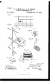
- Figure 1 isan elevation of a Wire fence showing our device as in use in weaving in a continuous stay wire.
- Fig. 2 is a vertical, central section through the device.
- Fig. 3 is a detached perspective View of the wire spool.
- Fig. 4 is an enlarged perspective view of the device asin use, showing a slightly modified form of-wire holder.
- Fig. 5 is a perspective View of the wire coil designed to be used in connection with the construction shown in Fig. 4.
- Fig. 6 is a detail section through the spacing standard illustrating its construction.
- Our invention consists of a lever or frame comprising the two legs A connected by the cross-bar B, the whole being substantially a U-shaped frame bent from a bar of metal.
- a crossbar or post E upon which is journaled a spool F.
- This spool receives a coil of stay wire G which may be wound thereon in any desired manner.
- the spool F is used a large amount of stay wire may be coiled thereon to construct acontinuous stay as shown in Fig. 1, but where it is desired to apply independent stays we prefer to use a construction shown in Fig. 4, in which the spool is in the shape of a pin H upon which a coil Iis adapted to engage, this coil having been previously formed upon a suitable mandrel and terminating in a hook J by means of which it maybe engaged upon the top wire of a fence.
- the spacing standard is preferably of the construction shown in Figs. 1, 4, and 6, comprising a main bar K provided with side notchesL arranged at the same distance apart as the fence wire and with which the fence wires are adapted to engage.
- This main standard at its bottom is provided with a foot M by means of which it may be supported and slid along the ground.
- N is a clamping bar beside the standard K by means of which proper tension may be applied to the wires through the medium of the bolts a and the winged nuts b, as plainly shown in Fig. 6.
- the operation of the device is as follows: The longitudinal wires of the fence being stretched, and the spacing standard engaged therewith, the end of the stay wire on the spool of the weaving machine is engaged with the top fence wire and the notches in the lower end of the frame engage with the next fence wire, as shown in Fig. 4.
- the natural shape of the' Wire when coiled on the spool is sufficient to apply the desired tension to the wire.
- the frame being turned about the fence wire on its foot will form a coil P tightly about the fence wire of any desired number of turns.
- the operator then disengages the foot from the fence wire by drawing downward on the frame and engages the foot with the next wire and proceeds in the same manner. If the spool is used for making a series of fence stays the operator simply removes the device from the fence and formsalong spiral around the bottom and top wires, as shown in Fig. 1 between the adjacent stays.
Landscapes
- Engineering & Computer Science (AREA)
- Mechanical Engineering (AREA)
- Fencing (AREA)
Description
(No Model.) I
. E. H. STOWELL & G'. W. TERRY.
WIRE STAY WEAVINGDBVIGE.
No. 529,211. Patented Nov. 13, 1894'.
UNHTE ELMER H. STOW ELL, OF DRAYTON PLAINS, AND GEORGE "W. TERRY, OF PONTIAC, MICHIGAN.
WI RE-STAY-WEAVI NG DEVICE.
EllEGIFICATION forming part of Letters Patent No. 529,21 1, dated November 13, 1894:.
Application filed August 23, 1894- Serial No. 5211 (NO 111011613 T at whom, it may concern;
Be it known that we, ELMER H. STOW LL,
of Drayton Plains, and GEORGE W. TERRY, residing at Pontiac,in the county of Oakland and State of Michigan, have invented certain new and useful Improvements in Wire-Stay Weaving Devices, of which the following is a specification, reference being bad therein to the accompanying drawings.
The invention consists in the peculiar construction of a frame or lever notched at one endv to engage upon the wire of a fence and having a spool or, pin upon which the stay wire may be wound so that by engaging the frame with a fence wire, the end of the stay wire being previously secured to an adjacent wire, the frame may be turned about the second wire and thus weave in a stay or tie wire in a wire fence.
The invention further consists in the peculiar construction, arrangement and combination of the various parts.
In the drawings, Figure 1 isan elevation of a Wire fence showing our device as in use in weaving in a continuous stay wire. Fig. 2 is a vertical, central section through the device. Fig. 3 is a detached perspective View of the wire spool. Fig. 4 is an enlarged perspective view of the device asin use, showing a slightly modified form of-wire holder. Fig. 5 is a perspective View of the wire coil designed to be used in connection with the construction shown in Fig. 4. Fig. 6 is a detail section through the spacing standard illustrating its construction.
In the prior state of the art it is usual in the construction of fences consisting of longitudinal wires to tie them together by means of tie or stay wires and our invention consists in the peculiar construction of a hand device designed to weave a tie or stay wire into such fences and is particularly designed to produce a cheap device, which not only will bind the stay wire about the fence wire but will also produce the desired tension on the stay wire which is an essential feature of such fences.
Our invention consists of a lever or frame comprising the two legs A connected by the cross-bar B, the whole being substantially a U-shaped frame bent from a bar of metal.
At the foot of these legs are tapering bifur cations O, at the end of which is a wire-bearing D of a size to readily engage the fence wireuponwhich the device is designedto work.
Near the top of the frame is a crossbar or post E upon which is journaled a spool F. This spool receives a coil of stay wire G which may be wound thereon in any desired manner. Where the spool F is used a large amount of stay wire may be coiled thereon to construct acontinuous stay as shown in Fig. 1, but where it is desired to apply independent stays we prefer to use a construction shown in Fig. 4, in which the spool is in the shape of a pin H upon which a coil Iis adapted to engage, this coil having been previously formed upon a suitable mandrel and terminating in a hook J by means of which it maybe engaged upon the top wire of a fence.
The spacing standard is preferably of the construction shown in Figs. 1, 4, and 6, comprising a main bar K provided with side notchesL arranged at the same distance apart as the fence wire and with which the fence wires are adapted to engage. This main standard at its bottom is provided with a foot M by means of which it may be supported and slid along the ground.
N is a clamping bar beside the standard K by means of which proper tension may be applied to the wires through the medium of the bolts a and the winged nuts b, as plainly shown in Fig. 6.
The operation of the device is as follows: The longitudinal wires of the fence being stretched, and the spacing standard engaged therewith, the end of the stay wire on the spool of the weaving machine is engaged with the top fence wire and the notches in the lower end of the frame engage with the next fence wire, as shown in Fig. 4. The operator now taking hold of the cross-bar B presses downward and the frame fulcrumed on its foot on the fence wire will act as a lever to uncoil the wire from the spool. The natural shape of the' Wire when coiled on the spool is sufficient to apply the desired tension to the wire. The frame being turned about the fence wire on its foot will form a coil P tightly about the fence wire of any desired number of turns. The operator then disengages the foot from the fence wire by drawing downward on the frame and engages the foot with the next wire and proceeds in the same manner. If the spool is used for making a series of fence stays the operator simply removes the device from the fence and formsalong spiral around the bottom and top wires, as shown in Fig. 1 between the adjacent stays.
By using a frame of this construction in which the power is applied through a lever we are enabled to form a very tight coil about the fence wires and at the same time produceconsiderable tension on the stay wire between the fence wires, the fence wires being prevented from approaching each other by the spacing standard.
What we claim as our invention is- In testimony whereofwe ailix our signatures 2 in presence of three witnesses.
ELMER H. S'IOWELL. GEORGE W. TERRY. Witnesses:
DAVID S. HOWARD, JOHN H. PATTERSON, JAMES S. GRAY.
Publications (1)
| Publication Number | Publication Date |
|---|---|
| US529211A true US529211A (en) | 1894-11-13 |
Family
ID=2597993
Family Applications (1)
| Application Number | Title | Priority Date | Filing Date |
|---|---|---|---|
| US529211D Expired - Lifetime US529211A (en) | Wire-stay-weaving device |
Country Status (1)
| Country | Link |
|---|---|
| US (1) | US529211A (en) |
-
0
- US US529211D patent/US529211A/en not_active Expired - Lifetime
Similar Documents
| Publication | Publication Date | Title |
|---|---|---|
| US529211A (en) | Wire-stay-weaving device | |
| US508297A (en) | Fence | |
| US697357A (en) | Fence-machine. | |
| US606120A (en) | Wire-fence machine | |
| US529374A (en) | Wire-stretcher | |
| US582370A (en) | Fence twisting-tool | |
| US324285A (en) | James withington | |
| US566408A (en) | Straining post foe wire fences | |
| US519995A (en) | feisbee | |
| US640772A (en) | Fence-machine. | |
| US406490A (en) | Device for attaching pickets to wire fences | |
| US500033A (en) | Fence | |
| US1091590A (en) | Package of fencing material. | |
| US601041A (en) | Mads mogenson | |
| US1192060A (en) | Fence structure. | |
| US567713A (en) | Fence-wire-winding device | |
| US1088469A (en) | Wire-fence stretcher. | |
| US565616A (en) | Metallic fence | |
| US522375A (en) | Wire fence | |
| US591703A (en) | Laban soseman | |
| US266864A (en) | Wire-stretcher | |
| US1035102A (en) | Anchor-plate. | |
| US428763A (en) | Fence | |
| US624730A (en) | Tension device for fence-wires | |
| US571930A (en) | Tension device for wire fences |