US5286133A - Joint for vehicle steering linkage - Google Patents
Joint for vehicle steering linkage Download PDFInfo
- Publication number
- US5286133A US5286133A US07/745,523 US74552391A US5286133A US 5286133 A US5286133 A US 5286133A US 74552391 A US74552391 A US 74552391A US 5286133 A US5286133 A US 5286133A
- Authority
- US
- United States
- Prior art keywords
- clamping
- sleeve
- screw thread
- internal
- external
- Prior art date
- Legal status (The legal status is an assumption and is not a legal conclusion. Google has not performed a legal analysis and makes no representation as to the accuracy of the status listed.)
- Expired - Lifetime
Links
Images
Classifications
-
- B—PERFORMING OPERATIONS; TRANSPORTING
- B62—LAND VEHICLES FOR TRAVELLING OTHERWISE THAN ON RAILS
- B62D—MOTOR VEHICLES; TRAILERS
- B62D7/00—Steering linkage; Stub axles or their mountings
- B62D7/20—Links, e.g. track rods
-
- F—MECHANICAL ENGINEERING; LIGHTING; HEATING; WEAPONS; BLASTING
- F16—ENGINEERING ELEMENTS AND UNITS; GENERAL MEASURES FOR PRODUCING AND MAINTAINING EFFECTIVE FUNCTIONING OF MACHINES OR INSTALLATIONS; THERMAL INSULATION IN GENERAL
- F16B—DEVICES FOR FASTENING OR SECURING CONSTRUCTIONAL ELEMENTS OR MACHINE PARTS TOGETHER, e.g. NAILS, BOLTS, CIRCLIPS, CLAMPS, CLIPS OR WEDGES; JOINTS OR JOINTING
- F16B2200/00—Constructional details of connections not covered for in other groups of this subclass
- F16B2200/69—Redundant disconnection blocking means
- F16B2200/73—Cam locks or thread locks
-
- Y—GENERAL TAGGING OF NEW TECHNOLOGICAL DEVELOPMENTS; GENERAL TAGGING OF CROSS-SECTIONAL TECHNOLOGIES SPANNING OVER SEVERAL SECTIONS OF THE IPC; TECHNICAL SUBJECTS COVERED BY FORMER USPC CROSS-REFERENCE ART COLLECTIONS [XRACs] AND DIGESTS
- Y10—TECHNICAL SUBJECTS COVERED BY FORMER USPC
- Y10T—TECHNICAL SUBJECTS COVERED BY FORMER US CLASSIFICATION
- Y10T403/00—Joints and connections
- Y10T403/32—Articulated members
- Y10T403/32114—Articulated members including static joint
- Y10T403/32196—Articulate joint is ball and socket
- Y10T403/32204—Articulate joint is ball and socket with threaded joint
-
- Y—GENERAL TAGGING OF NEW TECHNOLOGICAL DEVELOPMENTS; GENERAL TAGGING OF CROSS-SECTIONAL TECHNOLOGIES SPANNING OVER SEVERAL SECTIONS OF THE IPC; TECHNICAL SUBJECTS COVERED BY FORMER USPC CROSS-REFERENCE ART COLLECTIONS [XRACs] AND DIGESTS
- Y10—TECHNICAL SUBJECTS COVERED BY FORMER USPC
- Y10T—TECHNICAL SUBJECTS COVERED BY FORMER US CLASSIFICATION
- Y10T403/00—Joints and connections
- Y10T403/53—Split end with laterally movable opposed portions
- Y10T403/535—Split end with laterally movable opposed portions with separate force-applying means
-
- Y—GENERAL TAGGING OF NEW TECHNOLOGICAL DEVELOPMENTS; GENERAL TAGGING OF CROSS-SECTIONAL TECHNOLOGIES SPANNING OVER SEVERAL SECTIONS OF THE IPC; TECHNICAL SUBJECTS COVERED BY FORMER USPC CROSS-REFERENCE ART COLLECTIONS [XRACs] AND DIGESTS
- Y10—TECHNICAL SUBJECTS COVERED BY FORMER USPC
- Y10T—TECHNICAL SUBJECTS COVERED BY FORMER US CLASSIFICATION
- Y10T403/00—Joints and connections
- Y10T403/70—Interfitted members
- Y10T403/7047—Radially interposed shim or bushing
- Y10T403/7051—Wedging or camming
- Y10T403/7052—Engaged by axial movement
- Y10T403/7056—Threaded actuator
Definitions
- the present invention relates to a joint for a vehicle steering linkage.
- U.S. Pat. No. 5,004,367 discloses a joint in a vehicle steering linkage.
- the joint disclosed in the '367 patent comprises an internally threaded sleeve in which a threaded rod extends.
- the sleeve is made from a metal blank which is formed into a tubular shape, and has a longitudinal seam which is defined by adjoining edges of the metal blank.
- the sleeve also has a frusto-conical outer surface extending circumferentially around the sleeve.
- the joint disclosed in the '367 patent further comprises a nut having an internal thread engaged with the thread on the rod.
- the nut has a frusto-conical inner surface complementary to the frusto-conical outer surface on the sleeve.
- a joint connects a threaded rod in a vehicle steering linkage with another member in the vehicle steering linkage.
- the joint comprises a housing and a ball stud.
- the housing includes a socket and a sleeve extending from the socket along an axis.
- the sleeve has an opening for insertion of the rod, and has an internal thread engageable with the thread on the rod.
- the sleeve also has an external, first clamping surface inclined with respect to the axis.
- the ball stud has a ball end and a shank. The ball end is located in the socket, and the shank has means for connecting the ball stud to the other member in the vehicle steering linkage.
- the joint further comprises a clamping means which develops a clamping force between the internal thread on the sleeve and the thread on the rod.
- the clamping means includes a clamping member and a thread means.
- the clamping member has a second clamping surface, and is free of a thread for engaging the thread on the rod.
- the thread means moves the clamping member relative to the sleeve and the rod, and moves the second clamping surface in sliding contact with the first clamping surface.
- the pressure exerted against the first clamping surface by the second clamping surface is transmitted to the engaged threads on the sleeve and the rod.
- the clamping means thus clamps the rod in the sleeve.
- the clamping member is an unthreaded ring receivable axially over the end of the sleeve.
- the first clamping surface on the sleeve is a frusto-conical external surface extending circumferentially around the sleeve
- the second clamping surface on the clamping member is a frusto-conical internal surface extending circumferentially around the inside of the clamping member.
- the thread means comprises an internal thread on a nut which is threaded on the rod. The nut pushes the clamping member onto the sleeve when the nut is moved on the rod axially toward the sleeve.
- the sleeve has an external thread
- the clamping member has an internal thread engaged with the external thread on the sleeve.
- the second clamping surface on the clamping member is movable against the first clamping surface on the sleeve upon rotation of the clamping member about the sleeve.
- the external thread on the sleeve is a tapered thread on the first clamping surface
- the internal thread on the clamping member is a tapered thread on the second clamping surface.
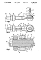
- FIG. 1 is a side view of a joint constructed in accordance with the invention
- FIG. 1A is a bottom view of the joint of FIG. 1;
- FIG. 2 is a sectional view taken on line 2--2 of FIG. 1A;
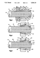
- FIG. 3 is a view of the joint of FIG. 2, showing parts in different positions;
- FIG. 4 is a partial sectional view of a portion of a joint constructed in accordance with an alternate embodiment of the invention.
- FIG. 5 is a partial sectional view of a portion of a joint constructed in accordance with another alternate embodiment of the invention.
- a joint 10 constructed in accordance with a preferred embodiment of the present invention comprises a housing 12 and a ball stud 14.
- a tie rod 16 is clamped securely in the housing 12 by a clamping member 18 and a nut 20.
- the housing 12 is formed from a metal blank which is shaped in a stamping process.
- the housing 12 has a first end portion including a socket 22, and has a second end portion including a sleeve 24.
- the housing 12 also has a longitudinally extending seam 26 which is defined by adjoining edge surfaces 28 and 30 of the metal blank from which the housing 12 is formed. The seam 26 enables the sleeve 24 to flex slightly with movement of the edge surfaces 28 and 30 relative to each other.
- the housing 12 is preferably formed of SAE grade 950 steel supplied by Worthington Steel Co. with the trademark "Maxi-form 50".
- the housing 12 can alternately be formed of any SAE/ASTM grade of stamping material suitable to meet the strength, ductility and formability requirements of the process and the final product application. Additionally, the housing 12 can be formed and assembled in accordance with the invention set forth in co-pending patent application Ser. No. 652,434 filed Feb. 8, 1991, entitled “Ball Joint and Method of Assembly", now U.S. Pat. No. 5,061,110.
- the ball stud 14 has a shank 32 with a thread 33 for connecting the ball stud 14 to another member (not shown) in the vehicle steering linkage, such as a steering arm.
- the ball stud 14 also has a ball end 34 encapsulated in a bearing 35 in the socket 22.
- the bearing 35 supports the ball stud 14 for limited pivotal movement about horizontal and vertical axes 36 and 38.
- the ball stud 14 is preferably formed of SAE 8115, 8615, 8640 or similar grade steel which is cold-formed or machined, carburized or carbonitrided to a 20-30 Rc core hardness and a 0.006-0.015 inch case depth, and may be supplied by Republic Steel Corp.
- the bearing 35 is preferably formed of an elastomeric material, and is most preferably formed of natural rubber (poly-isoprene) which is Banbury mixed and insert molded by injection and/or compression molding, and supplied by Yale-South Haven Inc. of South Haven, Mich.
- the ball stud 14 and the bearing 35 also can be formed and assembled as disclosed in co-pending patent application Ser. No. 652,434, now U.S. Pat. No. 5,061,110.
- the sleeve 24 has an annular end surface 40, a cylindrical outer surface 42, and an enlarged clamping portion 44 which is spaced axially from the end surface 40 by the cylindrical outer surface 42.
- the clamping portion 44 includes a first clamping surface 46.
- the first clamping surface 46 is a frusto-conical outer surface of the sleeve 24 extending circumferentially around the sleeve 24 from one edge surface 28 to the other edge surface 30. The first clamping surface 46 is thus inclined with respect to the horizontal axis 36 of the sleeve 24.
- the sleeve 24 also has an inner surface 50 with an internal thread 52.
- the internal thread 52 is interrupted by an unthreaded region 54 of the inner surface 50 which is deformed radially outward upon formation of the enlarged clamping portion 44 of the sleeve 24.
- the tie rod 16 has a circumferential screw thread 56 engaged with the internal thread 52 in the sleeve 24, and is thus movable axially and rotationally relative to the sleeve 24 upon rotation of the tie rod 16 in the sleeve 24.
- the tie rod 16 is preferably formed of SAE 8115 steel, and may be supplied by Republic Steel Corp.
- the nut 20 has an internal thread 60 engaged with the thread 56 on the tie rod 16.
- the nut 20 is thus movable axially and rotationally relative to the tie rod 16 and the sleeve 24 upon rotation of the nut 20 on the tie rod 16.
- the nut 20 also has an annular end surface 64 facing the annular end surface 40 on the sleeve 24.
- the nut 20 is formed of SAE 1033 steel, and may be supplied by R.B.& W. Manufacturing.
- the clamping member 18 is received axially over the sleeve 24, and is rotatable relative to the sleeve 24, the tie rod 16 and the nut 20.
- the clamping member 18 has a first annular end surface 68 defining a first open end of the clamping member 18, and has a second annular end surface 70 defining a second open end of the clamping member 18.
- a cylindrical inner surface 72 of the clamping member 18 extends axially from the first open end, and is receivable coaxially over the cylindrical outer surface 42 of the sleeve 24.
- a second clamping surface 74 extends axially from the second open end of the clamping member 18 to the cylindrical inner surface 72.
- the second clamping surface 74 is a frusto-conical inner surface extending circumferentially around the inside of the clamping member 18, and has a contour complementary to the contour of the first clamping surface 46 on the sleeve 24.
- the clamping member 18 is also preferably formed of SAE 1033 steel, and may be supplied by R.B.& W. Manufacturing.
- the nut 20 and the clamping member 18 are moved from the positions shown in FIG. 2 to the positions shown in FIG. 3.
- the nut 20 is moved axially on the tie rod 16 toward the sleeve 24, and contacts and pushes the clamping member 18 axially onto the sleeve 24.
- the annular end surface 64 on the nut 20 rotates in sliding contact with the first annular end surface 68 on the clamping member 18. Friction between those surfaces may cause the clamping member 18 to rotate about the sleeve 24 as it moves axially onto the sleeve 24.
- a clamping force begins to develop between the first clamping surface 46 on the sleeve 24 and the second clamping surface 74 on the clamping member 18 and when the second clamping surface 74 is moved into contact with the first clamping surface 46.
- the clamping force increases as the clamping member 18 is pushed by the nut 20 so as to advance axially onto the clamping portion 44 of the sleeve 24.
- the clamping force moves the edge surfaces 28 and 30 of the sleeve 24 toward each other. The sleeve 24 is thus flexed and clamped against the tie rod 16.
- the clamping member 18 is not threaded on the tie rod 16 and is not constrained to rotate with the nut 20.
- the clamping member 18 can therefore move axially over the clamping portion 44 of the sleeve 24 without necessarily rotating about the sleeve 24.
- the clamping member 18 moves onto the sleeve 24 more easily than it would if the second clamping surface 74 were constrained to rotate in sliding contact with the first clamping surface 46, because eccentricity between the first and second clamping surfaces 46 and 74, which could inhibit rotational sliding movement of those surfaces, will not inhibit axial sliding movement of those surfaces.
- the clamping member 18 will securely remain in its clamping position because it will not be urged to rotate out of its clamping position by torsional forces which act on and urge the sleeve 24 and the tie rod 16 to rotate relative to each other.
- an alternate embodiment of the invention comprises a sleeve 100 and a clamping member 102 which are preferably formed of the same materials as the sleeve 24 and the clamping member 18 described above, but which differ in shape from the sleeve 24 and the clamping member 18.
- the sleeve 100 is also formed from a metal blank which is shaped in a stamping process, and has a longitudinal seam which is defined in part by an edge surface 104.
- the sleeve 100 has an annular end surface 106, and a clamping portion 108 which extends axially inward and radially outward from the end surface 106.
- the clamping portion 108 has a frusto-conical outer clamping surface 110 with a tapered external thread 112.
- the sleeve 100 also has an inner surface 114 with an internal thread 116 which is interrupted at the clamping portion 108.
- the clamping member 102 is an annular member having a frusto-conical inner clamping surface 120 with a tapered internal thread 122. Like the clamping member 18 described above, the clamping member 102 is not threaded on the tie rod 16.
- the clamping member 102 is advanced axially onto the clamping portion 108 of the sleeve 100, with the internal thread 122 on the clamping member 102 engaged with the external thread 112 on the sleeve 100, a clamping force is developed between the inner and outer clamping surfaces 120 and 110. The sleeve 100 is thus clamped against the tie rod 16.
- another alternate embodiment of the invention comprises a sleeve 140 and a clamping member 142 which clamps the tie rod 16 in the sleeve 140.
- the sleeve 140 and the clamping member 142 are also preferably formed of the same materials as the sleeve 24 and the clamping member 18 described above.
- the sleeve 140 has an annular end surface 144, a cylindrical outer surface 146, and an enlarged clamping portion 148 which is spaced axially from the annular end surface 144 by the cylindrical outer surface 146.
- the clamping portion 148 has a frusto-conical outer clamping surface 150 with a tapered external thread 152.
- the sleeve 140 also has an inner surface 154 with an internal thread 156 which is interrupted at the clamping portion 148, and has a longitudinal seam which is defined in part by an edge surface 158.
- the clamping member 142 is an annular member having a first inner surface 160 extending axially from a first open end of the clamping member 142, and having a second inner surface 162 extending axially from a second open end of the clamping member 142.
- the first inner surface 160 is a cylindrical inner surface receivable coaxially over the cylindrical outer surface 146 on the sleeve 140, as shown in FIG. 5.
- the second inner surface 162 of the clamping member 142 is a frusto-conical inner clamping surface having a tapered thread 164. Like the clamping members 18 and 102 described above, the clamping member 142 is not threaded on the tie rod 16.
Landscapes
- Engineering & Computer Science (AREA)
- Chemical & Material Sciences (AREA)
- Combustion & Propulsion (AREA)
- Transportation (AREA)
- Mechanical Engineering (AREA)
- Steering-Linkage Mechanisms And Four-Wheel Steering (AREA)
Abstract
Description
Claims (10)
Priority Applications (1)
| Application Number | Priority Date | Filing Date | Title |
|---|---|---|---|
| US07/745,523 US5286133A (en) | 1991-08-15 | 1991-08-15 | Joint for vehicle steering linkage |
Applications Claiming Priority (1)
| Application Number | Priority Date | Filing Date | Title |
|---|---|---|---|
| US07/745,523 US5286133A (en) | 1991-08-15 | 1991-08-15 | Joint for vehicle steering linkage |
Publications (1)
| Publication Number | Publication Date |
|---|---|
| US5286133A true US5286133A (en) | 1994-02-15 |
Family
ID=24997043
Family Applications (1)
| Application Number | Title | Priority Date | Filing Date |
|---|---|---|---|
| US07/745,523 Expired - Lifetime US5286133A (en) | 1991-08-15 | 1991-08-15 | Joint for vehicle steering linkage |
Country Status (1)
| Country | Link |
|---|---|
| US (1) | US5286133A (en) |
Cited By (7)
| Publication number | Priority date | Publication date | Assignee | Title |
|---|---|---|---|---|
| US5484222A (en) * | 1993-10-08 | 1996-01-16 | Weatherford/Lamb, Inc. | Apparatus for gripping a pipe |
| US6604887B2 (en) * | 2000-02-28 | 2003-08-12 | Dana Corporation | Adjustable steering tie rod |
| US20050184266A1 (en) * | 2004-02-21 | 2005-08-25 | Enston Robert P. | Apparatus and method for the freeing of seized valves |
| US20050201821A1 (en) * | 2004-03-10 | 2005-09-15 | Trw Automotive U.S. Llc | Trunbuckle assembly |
| US20080302547A1 (en) * | 2004-07-03 | 2008-12-11 | Daniel Vergara | Handle, Lifting Spindle Arrangement, and Method for the Production of a Handle |
| US20110038665A1 (en) * | 2008-04-25 | 2011-02-17 | Zf Friedrichshafen Ag | Structural unit |
| DE102010040419A1 (en) * | 2010-09-08 | 2012-03-08 | Zf Friedrichshafen Ag | Clamp-free clamping bandage |
Citations (16)
| Publication number | Priority date | Publication date | Assignee | Title |
|---|---|---|---|---|
| US1016835A (en) * | 1911-01-30 | 1912-02-06 | Jules Levy-Maurice | Stretcher. |
| US1418298A (en) * | 1919-12-29 | 1922-06-06 | Thomas J Gorman | Longitudinal rod adjustment |
| US1421866A (en) * | 1921-10-08 | 1922-07-04 | Veeder Mfg Co | Turnbuckle |
| GB343297A (en) * | 1930-02-04 | 1931-02-19 | Thomas Arthur Stevens | Improvements in ball and socket joints particularly for the controls of motor cars, motor cycles and the like |
| US2451062A (en) * | 1945-12-21 | 1948-10-12 | Thompson Prod Inc | Clamp assembly |
| US2696367A (en) * | 1949-05-13 | 1954-12-07 | A 1 Bit & Tool Company | Apparatus for stabilizing well drills |
| US2703723A (en) * | 1952-12-01 | 1955-03-08 | William M E Hess | Turnbuckle |
| US2885234A (en) * | 1954-07-08 | 1959-05-05 | Charles O Larson | Turnbuckle |
| US3349662A (en) * | 1965-06-23 | 1967-10-31 | Chester I Williams | Rotatively-set anchor assembly for a mine bolt |
| US3498652A (en) * | 1968-07-26 | 1970-03-03 | Trw Inc | Clamping device |
| GB1290109A (en) * | 1970-03-03 | 1972-09-20 | ||
| US3801207A (en) * | 1972-02-10 | 1974-04-02 | Trw Inc | Fail-safe turnbuckle |
| US4172676A (en) * | 1978-09-11 | 1979-10-30 | Eaton Corporation | Turnbuckle assembly |
| DE8602266U1 (en) * | 1986-01-30 | 1986-03-13 | Daimler-Benz Aktiengesellschaft, 70567 Stuttgart | Secured screw connection |
| US4657424A (en) * | 1985-12-24 | 1987-04-14 | Ford Motor Company | Nonrotatable clamp for automotive steering linkage |
| US5004367A (en) * | 1989-12-01 | 1991-04-02 | Trw Inc. | Turnbuckle assembly |
-
1991
- 1991-08-15 US US07/745,523 patent/US5286133A/en not_active Expired - Lifetime
Patent Citations (16)
| Publication number | Priority date | Publication date | Assignee | Title |
|---|---|---|---|---|
| US1016835A (en) * | 1911-01-30 | 1912-02-06 | Jules Levy-Maurice | Stretcher. |
| US1418298A (en) * | 1919-12-29 | 1922-06-06 | Thomas J Gorman | Longitudinal rod adjustment |
| US1421866A (en) * | 1921-10-08 | 1922-07-04 | Veeder Mfg Co | Turnbuckle |
| GB343297A (en) * | 1930-02-04 | 1931-02-19 | Thomas Arthur Stevens | Improvements in ball and socket joints particularly for the controls of motor cars, motor cycles and the like |
| US2451062A (en) * | 1945-12-21 | 1948-10-12 | Thompson Prod Inc | Clamp assembly |
| US2696367A (en) * | 1949-05-13 | 1954-12-07 | A 1 Bit & Tool Company | Apparatus for stabilizing well drills |
| US2703723A (en) * | 1952-12-01 | 1955-03-08 | William M E Hess | Turnbuckle |
| US2885234A (en) * | 1954-07-08 | 1959-05-05 | Charles O Larson | Turnbuckle |
| US3349662A (en) * | 1965-06-23 | 1967-10-31 | Chester I Williams | Rotatively-set anchor assembly for a mine bolt |
| US3498652A (en) * | 1968-07-26 | 1970-03-03 | Trw Inc | Clamping device |
| GB1290109A (en) * | 1970-03-03 | 1972-09-20 | ||
| US3801207A (en) * | 1972-02-10 | 1974-04-02 | Trw Inc | Fail-safe turnbuckle |
| US4172676A (en) * | 1978-09-11 | 1979-10-30 | Eaton Corporation | Turnbuckle assembly |
| US4657424A (en) * | 1985-12-24 | 1987-04-14 | Ford Motor Company | Nonrotatable clamp for automotive steering linkage |
| DE8602266U1 (en) * | 1986-01-30 | 1986-03-13 | Daimler-Benz Aktiengesellschaft, 70567 Stuttgart | Secured screw connection |
| US5004367A (en) * | 1989-12-01 | 1991-04-02 | Trw Inc. | Turnbuckle assembly |
Cited By (10)
| Publication number | Priority date | Publication date | Assignee | Title |
|---|---|---|---|---|
| US5484222A (en) * | 1993-10-08 | 1996-01-16 | Weatherford/Lamb, Inc. | Apparatus for gripping a pipe |
| US6604887B2 (en) * | 2000-02-28 | 2003-08-12 | Dana Corporation | Adjustable steering tie rod |
| US20050184266A1 (en) * | 2004-02-21 | 2005-08-25 | Enston Robert P. | Apparatus and method for the freeing of seized valves |
| US20050201821A1 (en) * | 2004-03-10 | 2005-09-15 | Trw Automotive U.S. Llc | Trunbuckle assembly |
| US7182544B2 (en) | 2004-03-10 | 2007-02-27 | Trw Automotive U.S. Llc | Turnbuckle assembly |
| US20080302547A1 (en) * | 2004-07-03 | 2008-12-11 | Daniel Vergara | Handle, Lifting Spindle Arrangement, and Method for the Production of a Handle |
| US20110038665A1 (en) * | 2008-04-25 | 2011-02-17 | Zf Friedrichshafen Ag | Structural unit |
| US8696232B2 (en) * | 2008-04-25 | 2014-04-15 | Zf Friedrichshafen | Structural unit with axial adjustment limiting elements |
| DE102010040419A1 (en) * | 2010-09-08 | 2012-03-08 | Zf Friedrichshafen Ag | Clamp-free clamping bandage |
| US9328749B2 (en) | 2010-09-08 | 2016-05-03 | Zf Friedrichshafen Ag | Bracket-less clamping assembly |
Similar Documents
| Publication | Publication Date | Title |
|---|---|---|
| US5066160A (en) | Ball joint | |
| US3389927A (en) | Joint assembly | |
| US5154530A (en) | Ball joint | |
| US5286133A (en) | Joint for vehicle steering linkage | |
| US5380114A (en) | Ball joint assembly and method of mounting | |
| US7484772B2 (en) | End connection for pipes and a method for its manufacture | |
| US11466727B2 (en) | Ball socket assembly, dust boot therefor and method of construction thereof | |
| US5346262A (en) | Tube connection | |
| US5143457A (en) | Elastic pivoting slide bearing | |
| US4685707A (en) | Superfine finish piping joint | |
| EP1179154A2 (en) | Pipe connector and method for production thereof | |
| US4765661A (en) | Union joint assembly | |
| US20090250837A1 (en) | Method of manufacture of a nut and tail assembly | |
| GB1601091A (en) | Structure and method for mounting ball joint | |
| US5997208A (en) | Adjustment for a ball joint assembly | |
| CN1155776C (en) | Jointing of joint body with rotatable connecting piece | |
| US5678934A (en) | Bearing housing with a protective cap | |
| EP0952362B1 (en) | Collet and method | |
| US4902158A (en) | Assembly of a ball joint shank and a tube | |
| US20040105722A1 (en) | Ball and socket joint | |
| WO1999055543A3 (en) | Rubber-cushioned ball joint with a bearing geometry which is optimized with regard to tension | |
| US5061110A (en) | Ball joint and method of assembly | |
| US5163772A (en) | Ball joint | |
| RU2080497C1 (en) | Method of manufacture of ball joint | |
| JP3468575B2 (en) | Manufacturing method of sliding bush |
Legal Events
| Date | Code | Title | Description |
|---|---|---|---|
| AS | Assignment |
Owner name: TRW INC., OHIO Free format text: ASSIGNMENT OF ASSIGNORS INTEREST.;ASSIGNOR:WOOD, RUEY E.;REEL/FRAME:005833/0635 Effective date: 19910820 |
|
| STCF | Information on status: patent grant |
Free format text: PATENTED CASE |
|
| FEPP | Fee payment procedure |
Free format text: PAYOR NUMBER ASSIGNED (ORIGINAL EVENT CODE: ASPN); ENTITY STATUS OF PATENT OWNER: LARGE ENTITY |
|
| FPAY | Fee payment |
Year of fee payment: 4 |
|
| FPAY | Fee payment |
Year of fee payment: 8 |
|
| AS | Assignment |
Owner name: JPMORGAN CHASE BANK, NEW YORK Free format text: THE US GUARANTEE AND COLLATERAL AGREEMENT;ASSIGNOR:TRW AUTOMOTIVE U.S. LLC;REEL/FRAME:014022/0720 Effective date: 20030228 |
|
| FPAY | Fee payment |
Year of fee payment: 12 |