US5285922A - Dual compartment storage tank - Google Patents
Dual compartment storage tank Download PDFInfo
- Publication number
- US5285922A US5285922A US08/038,890 US3889093A US5285922A US 5285922 A US5285922 A US 5285922A US 3889093 A US3889093 A US 3889093A US 5285922 A US5285922 A US 5285922A
- Authority
- US
- United States
- Prior art keywords
- bulkhead
- top cover
- compartments
- bottom wall
- side wall
- Prior art date
- Legal status (The legal status is an assumption and is not a legal conclusion. Google has not performed a legal analysis and makes no representation as to the accuracy of the status listed.)
- Expired - Fee Related
Links
- 230000009977 dual effect Effects 0.000 title claims abstract description 6
- 239000007788 liquid Substances 0.000 abstract description 17
- 230000005540 biological transmission Effects 0.000 abstract 1
- 238000010276 construction Methods 0.000 description 3
- 229910000831 Steel Inorganic materials 0.000 description 1
- 230000004888 barrier function Effects 0.000 description 1
- 239000002283 diesel fuel Substances 0.000 description 1
- 238000004519 manufacturing process Methods 0.000 description 1
- 239000000463 material Substances 0.000 description 1
- 125000006850 spacer group Chemical group 0.000 description 1
- 239000010959 steel Substances 0.000 description 1
- 238000013022 venting Methods 0.000 description 1
Images
Classifications
-
- B—PERFORMING OPERATIONS; TRANSPORTING
- B60—VEHICLES IN GENERAL
- B60P—VEHICLES ADAPTED FOR LOAD TRANSPORTATION OR TO TRANSPORT, TO CARRY, OR TO COMPRISE SPECIAL LOADS OR OBJECTS
- B60P3/00—Vehicles adapted to transport, to carry or to comprise special loads or objects
- B60P3/22—Tank vehicles
- B60P3/24—Tank vehicles compartmented
- B60P3/243—Tank vehicles compartmented divided by rigid walls
-
- B—PERFORMING OPERATIONS; TRANSPORTING
- B65—CONVEYING; PACKING; STORING; HANDLING THIN OR FILAMENTARY MATERIAL
- B65D—CONTAINERS FOR STORAGE OR TRANSPORT OF ARTICLES OR MATERIALS, e.g. BAGS, BARRELS, BOTTLES, BOXES, CANS, CARTONS, CRATES, DRUMS, JARS, TANKS, HOPPERS, FORWARDING CONTAINERS; ACCESSORIES, CLOSURES, OR FITTINGS THEREFOR; PACKAGING ELEMENTS; PACKAGES
- B65D88/00—Large containers
- B65D88/02—Large containers rigid
- B65D88/06—Large containers rigid cylindrical
- B65D88/08—Large containers rigid cylindrical with a vertical axis
-
- B—PERFORMING OPERATIONS; TRANSPORTING
- B65—CONVEYING; PACKING; STORING; HANDLING THIN OR FILAMENTARY MATERIAL
- B65D—CONTAINERS FOR STORAGE OR TRANSPORT OF ARTICLES OR MATERIALS, e.g. BAGS, BARRELS, BOTTLES, BOXES, CANS, CARTONS, CRATES, DRUMS, JARS, TANKS, HOPPERS, FORWARDING CONTAINERS; ACCESSORIES, CLOSURES, OR FITTINGS THEREFOR; PACKAGING ELEMENTS; PACKAGES
- B65D90/00—Component parts, details or accessories for large containers
- B65D90/004—Contents retaining means
Definitions
- This invention relates generally to storage tanks and refers more particularly to a tank with two separate liquid storage compartments.
- One object of this invention is to provide a dual compartment storage tank which overcomes the problems associated with prior tanks of this type.
- the bulkhead is curved in an arc rather than flat and is therefore much more resistant to unequal pressures.
- Another object is to provide a dual storage tank which is composed of a relatively few simple parts, is rugged and durable in use, and is easy to manufacture, maintain and assemble.
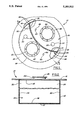
- FIG. 1 is a top plan view of a dual storage tank, with parts broken away, constructed in accordance with this invention.
- FIG. 2 is a sectional view taken on the line 2--2 in FIG. 1.
- the tank 10 has a bottom wall 12 and a side wall 14.
- the bottom wall and side wall are formed integrally with each other.
- the bottom wall is circular and the side wall is cylindrical and extends vertically upwardly from the outer edge of the bottom wall.
- a top cover 16 extends over the top of the tank and is sealed to the side wall as by a continuous weld along the full extent of the upper edge of the side wall.
- the bottom wall, side wall and top cover define a completely closed and sealed interior space 20 which is divided into two separate liquid compartments 22 and 24 by a bulkhead 26.
- the two liquid compartments usually hold different liquids, such as gasoline and diesel fuel.
- the bulkhead is disposed in an upright, vertical position within the tank and is arcuately curved about a vertical axis on a radius which is substantially larger than the radius of the side wall of the tank.
- the bulkhead is made up of two substantially identical plates 28 and 30 which are coextensive and overlie one another in laterally spaced apart relation.
- the plates may be separated by spacers (not shown), if desired, so that there is a small gap or space 31 of uniform width between the plates.
- the plates may, for example, be 1/4" plates and the space between the plates may be 1/4" in width. These dimensions may vary, as desired.
- the entire tank, including the bottom wall, side wall, top cover and bulkhead are made of a strong material such as steel.
- the entire peripheries of the plates 28 and 30 are sealed to the interior of the tank so that the two compartments are completely separated and isolated from one another, preventing liquid transfer from one compartment to the other.
- the top edges of the plates of the bulkhead are secured to the top cover as by a weld 32.
- the opposite side edges of the bulkhead plates are secured to the side wall of the tank as by welds 34 and 36, and the bottom edges of the plates of the bulkhead are secured to the bottom wall of the tank as by a weld 38.
- Manholes 42 and 44 in the top cover 16 provide access to the two compartments. These manholes are closed by removable lids 46 and gaskets (not shown) to seal the manhole openings. The manholes permit a workman to enter both compartments in order to properly and completely weld the bulkhead in place and perform other necessary or desirable work on the tank.
- Fill openings 50 and 52 in the cover 16 are closed by removable plugs 54 and 56 and are provided for filling the compartments with liquid and for withdrawing liquid therefrom.
- Vent openings 58 and 60 in the cover have removable caps 62 and 64 for venting the two compartments as may be necessary.
- a curved bulkhead of the construction herein described is much more resistant to unequal pressures in the tank which may occur when the liquids in the two compartments are at different levels, as when liquid is withdrawn from one compartment but not the other.
- the curved bulkhead is also more resistant to unequal or differential pressures in the compartments 22 and 24 when one of the compartments is leak tested by the introduction of air under pressure.
- the double plate construction of the bulkhead 26 provides added protection against leakage from one compartment to the other. Also, the bulkhead may be tested for leaks by cutting through the top cover 16 and introducing air under pressure into the space between the bulkhead plates. The two liquid compartments 22 and 24 may be leak tested by introducing air under pressure through the fill openings 50, 52 or vents 58, 60.
Landscapes
- Engineering & Computer Science (AREA)
- Mechanical Engineering (AREA)
- Health & Medical Sciences (AREA)
- Public Health (AREA)
- Transportation (AREA)
- Filling Or Discharging Of Gas Storage Vessels (AREA)
Abstract
A dual compartment liquid storage tank has a bottom wall, an annular side wall extending upwardly from the bottom wall and a top cover, to define an interior space. A bulkhead extends across the interior space to divide it into two separate compartments completely isolated from one another. The bulkhead is arcuately curved about a vertical axis and is marginally sealed to the bottom and side walls and top cover to prevent transmission of liquid from one compartment to the other. The curved configuration of the bulkhead withstands pressure differentials due to unequally filled compartments without buckling or distortion or failure of the seals, more effectively than a flat bulkhead.
Description
This invention relates generally to storage tanks and refers more particularly to a tank with two separate liquid storage compartments.
In the past, storage tanks for two different liquids have been constructed with a flat barrier wall or bulkhead to divide the interior of the tank into two separate compartments. This construction is usually satisfactory when the liquid volume in both compartments is the same. However, a problem occurs when the liquid levels are substantially different. For example, after liquid is withdrawn or partially withdrawn from one compartment but not the other, the liquid pressure on the two sides of the flat bulkhead will be unequal and as a result the bulkhead may bulge or become warped or distorted, sometimes causing a failure of the weld between the bulkhead and the tank wall. The problem of unequal pressures also is present when one compartment or the other is tested for leaks by the introduction of air under pressure.
One object of this invention is to provide a dual compartment storage tank which overcomes the problems associated with prior tanks of this type. In accordance with a specific embodiment to be described, the bulkhead is curved in an arc rather than flat and is therefore much more resistant to unequal pressures.
Another object is to provide a dual storage tank which is composed of a relatively few simple parts, is rugged and durable in use, and is easy to manufacture, maintain and assemble.
Other objects, features and advantages of the invention will become more apparent as the following description proceeds, especially when considered with the accompanying drawings.
FIG. 1 is a top plan view of a dual storage tank, with parts broken away, constructed in accordance with this invention.
FIG. 2 is a sectional view taken on the line 2--2 in FIG. 1.
Referring now more particularly to the drawings, the tank 10 has a bottom wall 12 and a side wall 14. Preferably the bottom wall and side wall are formed integrally with each other. The bottom wall is circular and the side wall is cylindrical and extends vertically upwardly from the outer edge of the bottom wall.
A top cover 16 extends over the top of the tank and is sealed to the side wall as by a continuous weld along the full extent of the upper edge of the side wall.
The bottom wall, side wall and top cover define a completely closed and sealed interior space 20 which is divided into two separate liquid compartments 22 and 24 by a bulkhead 26. The two liquid compartments usually hold different liquids, such as gasoline and diesel fuel. The bulkhead is disposed in an upright, vertical position within the tank and is arcuately curved about a vertical axis on a radius which is substantially larger than the radius of the side wall of the tank.
The bulkhead is made up of two substantially identical plates 28 and 30 which are coextensive and overlie one another in laterally spaced apart relation. The plates may be separated by spacers (not shown), if desired, so that there is a small gap or space 31 of uniform width between the plates. The plates may, for example, be 1/4" plates and the space between the plates may be 1/4" in width. These dimensions may vary, as desired.
The entire tank, including the bottom wall, side wall, top cover and bulkhead are made of a strong material such as steel.
The entire peripheries of the plates 28 and 30 are sealed to the interior of the tank so that the two compartments are completely separated and isolated from one another, preventing liquid transfer from one compartment to the other. As seen in FIG. 2, the top edges of the plates of the bulkhead are secured to the top cover as by a weld 32. The opposite side edges of the bulkhead plates are secured to the side wall of the tank as by welds 34 and 36, and the bottom edges of the plates of the bulkhead are secured to the bottom wall of the tank as by a weld 38. These welds are continuous so that, as already stated, the two compartments are completely sealed from one another.
As stated above, it has been found that a curved bulkhead of the construction herein described, rather than a flat bulkhead, is much more resistant to unequal pressures in the tank which may occur when the liquids in the two compartments are at different levels, as when liquid is withdrawn from one compartment but not the other. The curved bulkhead is also more resistant to unequal or differential pressures in the compartments 22 and 24 when one of the compartments is leak tested by the introduction of air under pressure.
The double plate construction of the bulkhead 26 provides added protection against leakage from one compartment to the other. Also, the bulkhead may be tested for leaks by cutting through the top cover 16 and introducing air under pressure into the space between the bulkhead plates. The two liquid compartments 22 and 24 may be leak tested by introducing air under pressure through the fill openings 50, 52 or vents 58, 60.
Claims (1)
1. A dual compartment storage tank having a bottom wall, an annular side wall extending upwardly from said bottom wall, and a top cover, said bottom all, annular side wall and top cover defining a closed interior space, and a vertical bulkhead extending across said interior space and dividing it into two compartments, said bulkhead comprising a pair of substantially identical vertical arcuate plates which are curved about a common vertical axis throughout their entire lateral extent and are coextensive and overlie one another in closely laterally spaced apart relation, the bottom, side and upper edges of said plates being sealed to said bottom wall, side wall and top cover, respectively, along their entire peripheries so that said compartments are completely sealed and isolated from each other.
Priority Applications (1)
| Application Number | Priority Date | Filing Date | Title |
|---|---|---|---|
| US08/038,890 US5285922A (en) | 1993-03-29 | 1993-03-29 | Dual compartment storage tank |
Applications Claiming Priority (1)
| Application Number | Priority Date | Filing Date | Title |
|---|---|---|---|
| US08/038,890 US5285922A (en) | 1993-03-29 | 1993-03-29 | Dual compartment storage tank |
Publications (1)
| Publication Number | Publication Date |
|---|---|
| US5285922A true US5285922A (en) | 1994-02-15 |
Family
ID=21902488
Family Applications (1)
| Application Number | Title | Priority Date | Filing Date |
|---|---|---|---|
| US08/038,890 Expired - Fee Related US5285922A (en) | 1993-03-29 | 1993-03-29 | Dual compartment storage tank |
Country Status (1)
| Country | Link |
|---|---|
| US (1) | US5285922A (en) |
Cited By (9)
| Publication number | Priority date | Publication date | Assignee | Title |
|---|---|---|---|---|
| US5832575A (en) * | 1997-09-15 | 1998-11-10 | Sturino; David P. | Crematory urn |
| US6318581B1 (en) | 2000-03-06 | 2001-11-20 | Snyder Industries, Inc. | Discharge outlet for double wall containment tank assembly |
| US6474496B1 (en) | 2000-03-06 | 2002-11-05 | Snyder Industries, Inc. | Containment tank assembly |
| WO2004060776A1 (en) * | 2003-01-06 | 2004-07-22 | Gilbarco Inc. | Dual chambered dedicated underground storage tank |
| US20040177885A1 (en) * | 2003-03-14 | 2004-09-16 | Shepard Robert S. | Underground storage tank metering system in a service station environment |
| WO2008015668A2 (en) * | 2006-08-02 | 2008-02-07 | Keter Plastic Ltd. | Play device |
| US20080035649A1 (en) * | 2002-07-19 | 2008-02-14 | Volvo Lastvagnar Ab | Fuel tank |
| US20090166365A1 (en) * | 2007-12-31 | 2009-07-02 | Paccar Inc | Pressure vessel |
| US20130341333A1 (en) * | 2012-06-26 | 2013-12-26 | Steel Tank Institute | Storage tank with internal floor |
Citations (6)
| Publication number | Priority date | Publication date | Assignee | Title |
|---|---|---|---|---|
| US1595633A (en) * | 1924-12-19 | 1926-08-10 | Heil Co | Compartment-tank construction |
| US1808427A (en) * | 1929-12-07 | 1931-06-02 | Walter C Mcgaffic | Compartment tank construction |
| US2092392A (en) * | 1934-01-23 | 1937-09-07 | Westinghouse Air Brake Co | Multiple compartment reservoir |
| US2211239A (en) * | 1938-05-03 | 1940-08-13 | Earl C Liston | Tank construction for trailers and trucks |
| DE1088826B (en) * | 1956-11-12 | 1960-09-08 | Paul Brendel | Tank truck |
| US3310070A (en) * | 1961-04-21 | 1967-03-21 | Pullman Inc | Selective valve actuating mechanism for vessels |
-
1993
- 1993-03-29 US US08/038,890 patent/US5285922A/en not_active Expired - Fee Related
Patent Citations (6)
| Publication number | Priority date | Publication date | Assignee | Title |
|---|---|---|---|---|
| US1595633A (en) * | 1924-12-19 | 1926-08-10 | Heil Co | Compartment-tank construction |
| US1808427A (en) * | 1929-12-07 | 1931-06-02 | Walter C Mcgaffic | Compartment tank construction |
| US2092392A (en) * | 1934-01-23 | 1937-09-07 | Westinghouse Air Brake Co | Multiple compartment reservoir |
| US2211239A (en) * | 1938-05-03 | 1940-08-13 | Earl C Liston | Tank construction for trailers and trucks |
| DE1088826B (en) * | 1956-11-12 | 1960-09-08 | Paul Brendel | Tank truck |
| US3310070A (en) * | 1961-04-21 | 1967-03-21 | Pullman Inc | Selective valve actuating mechanism for vessels |
Cited By (14)
| Publication number | Priority date | Publication date | Assignee | Title |
|---|---|---|---|---|
| US5832575A (en) * | 1997-09-15 | 1998-11-10 | Sturino; David P. | Crematory urn |
| US6318581B1 (en) | 2000-03-06 | 2001-11-20 | Snyder Industries, Inc. | Discharge outlet for double wall containment tank assembly |
| US6474496B1 (en) | 2000-03-06 | 2002-11-05 | Snyder Industries, Inc. | Containment tank assembly |
| USRE39721E1 (en) | 2000-03-06 | 2007-07-10 | Snyder Industries, Inc. | Discharge outlet for double wall containment tank assembly |
| US20080035649A1 (en) * | 2002-07-19 | 2008-02-14 | Volvo Lastvagnar Ab | Fuel tank |
| WO2004060776A1 (en) * | 2003-01-06 | 2004-07-22 | Gilbarco Inc. | Dual chambered dedicated underground storage tank |
| US6929018B2 (en) | 2003-03-14 | 2005-08-16 | Gilbarco Inc. | Underground storage tank metering system in a service station environment |
| US6935356B2 (en) | 2003-03-14 | 2005-08-30 | Gilbarco Inc. | Underground storage tank metering system in a service station environment |
| US20040187933A1 (en) * | 2003-03-14 | 2004-09-30 | Shepard Robert S | Underground storage tank metering system in a service station environment |
| US20040177885A1 (en) * | 2003-03-14 | 2004-09-16 | Shepard Robert S. | Underground storage tank metering system in a service station environment |
| WO2008015668A2 (en) * | 2006-08-02 | 2008-02-07 | Keter Plastic Ltd. | Play device |
| WO2008015668A3 (en) * | 2006-08-02 | 2009-04-16 | Keter Plastic Ltd | Play device |
| US20090166365A1 (en) * | 2007-12-31 | 2009-07-02 | Paccar Inc | Pressure vessel |
| US20130341333A1 (en) * | 2012-06-26 | 2013-12-26 | Steel Tank Institute | Storage tank with internal floor |
Similar Documents
| Publication | Publication Date | Title |
|---|---|---|
| US5285922A (en) | Dual compartment storage tank | |
| US5582310A (en) | Above-grade storage vault | |
| US5076456A (en) | Containment sump with stackable extensions | |
| US4278892A (en) | Radioactivity-shielding transport or storage receptacle for radioactive wastes | |
| US4706718A (en) | Containment manhole having spillage sealing means | |
| US3924773A (en) | Fuel tank | |
| US8328040B2 (en) | Multiple-walled storage tank | |
| JPH0253245B2 (en) | ||
| US5593060A (en) | Plastic drum lid | |
| US5505327A (en) | Flexible lined tank with vacuum in the manway | |
| US5111955A (en) | Non-metallic acid hatch | |
| CA2059445C (en) | Double wall underground storage tank | |
| US5595319A (en) | Reusable container unit having spaced protective housings | |
| US3138173A (en) | Automatic pressure and vacuum cap | |
| US2219659A (en) | Heat exchanger | |
| US4168350A (en) | Explosion resistant battery cover design | |
| KR101506405B1 (en) | An LPG fuel tank with a ease of makingleaked gas airtight | |
| US8646478B2 (en) | Tank valve system | |
| US5893479A (en) | Storage tank vault | |
| US20190002195A1 (en) | Baffled fluid container assembly | |
| US7191792B2 (en) | Compressor assembly | |
| US8550104B2 (en) | Pressure control and relief system | |
| US2743841A (en) | Vent for metal housing for electrolytic | |
| US5454544A (en) | Storage vault cover casting assembly | |
| CA1109337A (en) | Railroad tank car |
Legal Events
| Date | Code | Title | Description |
|---|---|---|---|
| AS | Assignment |
Owner name: CLAWSON TANK COMPANY, MICHIGAN Free format text: ASSIGNMENT OF ASSIGNORS INTEREST.;ASSIGNOR:HARDING, CHARLES W.;REEL/FRAME:006500/0869 Effective date: 19930303 |
|
| FPAY | Fee payment |
Year of fee payment: 4 |
|
| REMI | Maintenance fee reminder mailed | ||
| LAPS | Lapse for failure to pay maintenance fees | ||
| STCH | Information on status: patent discontinuation |
Free format text: PATENT EXPIRED DUE TO NONPAYMENT OF MAINTENANCE FEES UNDER 37 CFR 1.362 |
|
| FP | Lapsed due to failure to pay maintenance fee |
Effective date: 20020215 |