US5269458A - Furnace monitoring and thermostat cycling system for recreational vehicles and marine vessels - Google Patents
Furnace monitoring and thermostat cycling system for recreational vehicles and marine vessels Download PDFInfo
- Publication number
- US5269458A US5269458A US08/004,268 US426893A US5269458A US 5269458 A US5269458 A US 5269458A US 426893 A US426893 A US 426893A US 5269458 A US5269458 A US 5269458A
- Authority
- US
- United States
- Prior art keywords
- signal
- furnace
- thermostat
- circuit
- generating
- Prior art date
- Legal status (The legal status is an assumption and is not a legal conclusion. Google has not performed a legal analysis and makes no representation as to the accuracy of the status listed.)
- Expired - Fee Related
Links
Images


Classifications
-
- B—PERFORMING OPERATIONS; TRANSPORTING
- B60—VEHICLES IN GENERAL
- B60H—ARRANGEMENTS OF HEATING, COOLING, VENTILATING OR OTHER AIR-TREATING DEVICES SPECIALLY ADAPTED FOR PASSENGER OR GOODS SPACES OF VEHICLES
- B60H1/00—Heating, cooling or ventilating [HVAC] devices
- B60H1/22—Heating, cooling or ventilating [HVAC] devices the heat being derived otherwise than from the propulsion plant
- B60H1/2203—Heating, cooling or ventilating [HVAC] devices the heat being derived otherwise than from the propulsion plant the heat being derived from burners
- B60H1/2206—Heating, cooling or ventilating [HVAC] devices the heat being derived otherwise than from the propulsion plant the heat being derived from burners controlling the operation of burners
-
- B—PERFORMING OPERATIONS; TRANSPORTING
- B60—VEHICLES IN GENERAL
- B60H—ARRANGEMENTS OF HEATING, COOLING, VENTILATING OR OTHER AIR-TREATING DEVICES SPECIALLY ADAPTED FOR PASSENGER OR GOODS SPACES OF VEHICLES
- B60H1/00—Heating, cooling or ventilating [HVAC] devices
- B60H1/00357—Air-conditioning arrangements specially adapted for particular vehicles
- B60H1/00364—Air-conditioning arrangements specially adapted for particular vehicles for caravans or trailers
-
- F—MECHANICAL ENGINEERING; LIGHTING; HEATING; WEAPONS; BLASTING
- F23—COMBUSTION APPARATUS; COMBUSTION PROCESSES
- F23N—REGULATING OR CONTROLLING COMBUSTION
- F23N5/00—Systems for controlling combustion
- F23N5/24—Preventing development of abnormal or undesired conditions, i.e. safety arrangements
- F23N5/242—Preventing development of abnormal or undesired conditions, i.e. safety arrangements using electronic means
-
- B—PERFORMING OPERATIONS; TRANSPORTING
- B60—VEHICLES IN GENERAL
- B60H—ARRANGEMENTS OF HEATING, COOLING, VENTILATING OR OTHER AIR-TREATING DEVICES SPECIALLY ADAPTED FOR PASSENGER OR GOODS SPACES OF VEHICLES
- B60H1/00—Heating, cooling or ventilating [HVAC] devices
- B60H1/22—Heating, cooling or ventilating [HVAC] devices the heat being derived otherwise than from the propulsion plant
- B60H2001/2228—Heating, cooling or ventilating [HVAC] devices the heat being derived otherwise than from the propulsion plant controlling the operation of heaters
- B60H2001/224—Heating, cooling or ventilating [HVAC] devices the heat being derived otherwise than from the propulsion plant controlling the operation of heaters automatic operation, e.g. control circuits or methods
-
- B—PERFORMING OPERATIONS; TRANSPORTING
- B60—VEHICLES IN GENERAL
- B60H—ARRANGEMENTS OF HEATING, COOLING, VENTILATING OR OTHER AIR-TREATING DEVICES SPECIALLY ADAPTED FOR PASSENGER OR GOODS SPACES OF VEHICLES
- B60H1/00—Heating, cooling or ventilating [HVAC] devices
- B60H1/22—Heating, cooling or ventilating [HVAC] devices the heat being derived otherwise than from the propulsion plant
- B60H2001/2246—Heating, cooling or ventilating [HVAC] devices the heat being derived otherwise than from the propulsion plant obtaining information from a variable, e.g. by means of a sensor
- B60H2001/2256—Heating, cooling or ventilating [HVAC] devices the heat being derived otherwise than from the propulsion plant obtaining information from a variable, e.g. by means of a sensor related to the operation of the heater itself, e.g. flame detection or overheating
-
- B—PERFORMING OPERATIONS; TRANSPORTING
- B60—VEHICLES IN GENERAL
- B60H—ARRANGEMENTS OF HEATING, COOLING, VENTILATING OR OTHER AIR-TREATING DEVICES SPECIALLY ADAPTED FOR PASSENGER OR GOODS SPACES OF VEHICLES
- B60H1/00—Heating, cooling or ventilating [HVAC] devices
- B60H1/22—Heating, cooling or ventilating [HVAC] devices the heat being derived otherwise than from the propulsion plant
- B60H2001/2268—Constructional features
- B60H2001/2293—Integration into other parts of a vehicle
-
- F—MECHANICAL ENGINEERING; LIGHTING; HEATING; WEAPONS; BLASTING
- F23—COMBUSTION APPARATUS; COMBUSTION PROCESSES
- F23N—REGULATING OR CONTROLLING COMBUSTION
- F23N2225/00—Measuring
- F23N2225/04—Measuring pressure
-
- F—MECHANICAL ENGINEERING; LIGHTING; HEATING; WEAPONS; BLASTING
- F23—COMBUSTION APPARATUS; COMBUSTION PROCESSES
- F23N—REGULATING OR CONTROLLING COMBUSTION
- F23N2225/00—Measuring
- F23N2225/08—Measuring temperature
-
- F—MECHANICAL ENGINEERING; LIGHTING; HEATING; WEAPONS; BLASTING
- F23—COMBUSTION APPARATUS; COMBUSTION PROCESSES
- F23N—REGULATING OR CONTROLLING COMBUSTION
- F23N2227/00—Ignition or checking
- F23N2227/12—Burner simulation or checking
- F23N2227/16—Checking components, e.g. electronic
-
- F—MECHANICAL ENGINEERING; LIGHTING; HEATING; WEAPONS; BLASTING
- F23—COMBUSTION APPARATUS; COMBUSTION PROCESSES
- F23N—REGULATING OR CONTROLLING COMBUSTION
- F23N2227/00—Ignition or checking
- F23N2227/32—Igniting for a predetermined number of cycles
-
- F—MECHANICAL ENGINEERING; LIGHTING; HEATING; WEAPONS; BLASTING
- F23—COMBUSTION APPARATUS; COMBUSTION PROCESSES
- F23N—REGULATING OR CONTROLLING COMBUSTION
- F23N2231/00—Fail safe
- F23N2231/12—Fail safe for ignition failures
-
- F—MECHANICAL ENGINEERING; LIGHTING; HEATING; WEAPONS; BLASTING
- F23—COMBUSTION APPARATUS; COMBUSTION PROCESSES
- F23N—REGULATING OR CONTROLLING COMBUSTION
- F23N2231/00—Fail safe
- F23N2231/20—Warning devices
-
- F—MECHANICAL ENGINEERING; LIGHTING; HEATING; WEAPONS; BLASTING
- F23—COMBUSTION APPARATUS; COMBUSTION PROCESSES
- F23N—REGULATING OR CONTROLLING COMBUSTION
- F23N2233/00—Ventilators
- F23N2233/06—Ventilators at the air intake
-
- F—MECHANICAL ENGINEERING; LIGHTING; HEATING; WEAPONS; BLASTING
- F23—COMBUSTION APPARATUS; COMBUSTION PROCESSES
- F23N—REGULATING OR CONTROLLING COMBUSTION
- F23N2239/00—Fuels
- F23N2239/04—Gaseous fuels
-
- F—MECHANICAL ENGINEERING; LIGHTING; HEATING; WEAPONS; BLASTING
- F23—COMBUSTION APPARATUS; COMBUSTION PROCESSES
- F23N—REGULATING OR CONTROLLING COMBUSTION
- F23N2241/00—Applications
- F23N2241/14—Vehicle heating, the heat being derived otherwise than from the propulsion plant
Definitions
- the present invention relates generally to a device for use in mobile recreational vehicles, marine vessels, and other such mobile self-contained living environments.
- the device monitors ga furnace heater operation and cabin environment temperature and if the furnace fails to light automatically cycles the thermostat to retry for furnace ignition.
- Typical mobile recreational vehicles RV's
- houseboats marine vessels
- other such mobile self-contained environments provide for cabin environment heating by a thermostatically controlled furnace which is typically fueled by combusting a portable supply of liquefied petroleum gas (LPG), also known as propane.
- LPG liquefied petroleum gas
- the furnace is typically powered by an on board battery for electrical demands such as blower or fan operation, opening and closing burner valves, and spark ignition functions.
- a thermostat mounted in the RV or the like acts like a thermal switch, closing when sensing the ambient temperature has fallen below a desired setpoint temperature. The furnace senses the closed switch through the electrical connections and turns on to provide heat and raise the temperature.
- Another common problem relating to the ignition failures of typical RV furnaces also relates to the propane system.
- the liquified petroleum gas is stored in a liquid form under relatively high pressure in the LPG supply tank.
- Gas pressure regulators are normally installed at or near the propane tank and regulate the gas pressure in the lines, providing the propane gas at their outlets at a relatively low pressure.
- the gas pressure regulators often fail to regulate the pressure in the lines within the range suitable for ignition at the furnace. Further, even with a good pressure regulator the gas pressure delivered to the furnace may be low due to excessive flow to other propane fueled appliances simultaneously demanding flow of propane.
- occupant cooking, water heater turn-on, and absorption refrigerator burner turn-on may all occur simultaneously, increasing the propane gas flow demand and possibly causing a low propane gas pressure to exist downstream of the pressure regulator.
- a low gas pressure supplied to the heating furnace may lead to ignition failure, as well as inoperability of other propane fueled appliances in the RV.
- thermostat design Various examples of the prior art exist for thermostat design, but these are not central to the present invention nor its autonomous operation which only interfaces with such various devices as thermostats in an RV and is not concerned with the internal operation or detailed design of same.
- U.S. Pat. No. 3,621,434 of Gerich provides for a detailed mechanism internal to the workings of a trip-free manual reset thermostat but does not address the need in the art discussed herein.
- U.S. Pat. No. 3,861,589 of Carlson provides for an electronic thermostat accepting either AC or DC current and provides for a clean circuit opening when the applied circuit voltage is low. These are advantageous in the case of controlling the winding of a solenoid valve to supply gas to a furnace, but does not meet the need in the art for autonomous detection of RV furnace ignition failure due to gas depletion or low voltage or marginal operating conditions.
- U.S. Pat. No. 4,338,891 of Blitz controls the temperature in automotive storage compartments integral with the fluid cooled internal transport system of the internal combustion engine of the self-powered vehicle by circulating engine coolant fluid through a heat exchanger.
- a gas furnace heating unit controlled by a thermostat in an RV or similar environment the heating systems of which are independent from the transport engine, if one even exists in the RV (such as for example would not be the case with a towable trailer).
- U.S. Pat. No. 4,420,033 of Franz controls the temperature in vehicle passenger compartments through a vacuum operated servoactuator which cycles the cooling refrigerant compressor and modulates the heater core water valve of the vehicle.
- a vacuum operated servoactuator which cycles the cooling refrigerant compressor and modulates the heater core water valve of the vehicle.
- U.S. Pat No. 4,750,671 of Heinle et al provides a regulating device for a heating system of a motor vehicle by regulating air flow so as to balance the air temperatures of driver and passenger sides through throttle valve regulation and so does not meet the need in the art to address the ignition shortcomings of a gas furnace heating unit controlled by a thermostat in an RV or similar environment.
- U.S. Pat. No. 4,543,795 of Ward et al provides for regulating the temperature within the cabin of a vehicle such as a truck tractor or an agricultural vehicle with a power circuit which applies electrical power to a heating/cooling device and so does not meet the need in the art to address the ignition shortcomings of a gas furnace heating unit controlled by a thermostat in an RV or similar environment.
- U.S. Pat. No. 4,514,976 of Christoff relates to environmental control units for aircraft and the like through an improved integration with the compressor turbomachinery of such vehicles as large passenger planes and so does not meet the need in the art to address the ignition shortcomings of a gas furnace heating unit controlled by a thermostat in an RV or similar environment, the heating systems of which are independent from turbomachinery, which do not exist in an RV.
- U.S. Pat. No. 4,308,993 of Buss is also a heating system for aircraft cabins which uses engine bleed air or compressor air for heating the passenger space and so similarly does not meet the need in the art to address the ignition shortcomings of a gas furnace heating unit controlled by a thermostat in an RV or similar environment.
- U.S. Pat. No. 4,784,214 of Penson et al relates to a secondary remote control system for an RV's air conditioning unit, typically roof mounted and possibly including an auxiliary heating unit.
- the auxiliary heating unit is a resistive electrical strip and so does not meet the need in the art to address the ignition shortcomings of a gas furnace heating unit controlled by a thermostat in an RV or similar environment.
- the prior art provides for displaying the level of propane in the supply tank as it exists stored under high pressure in its liquid form, the art does not provide for monitoring the gas pressure in an RV as delivered to the furnace and other appliances, downstream of the pressure regulator.
- Commercially available dial gages are available and can be utilized for diagnostic purposes on the propane system of an RV, but being a portable tool by nature are designed only for temporary use and can only be read locally at the point of mechanical connection.
- the prior art provide for the indication or alarm of too low or too high a gas pressure being supplied to the propane fueled furnace or other appliances of an RV.
- the prior art does not satisfy the need for a system which detects the failure of a typical RV furnace to ignite and cycles or resets the thermostat until ignition occurs, thereby preventing the blowing of cold air and battery depletion.
- the prior art satisfy the need for autonomous operation such that when the propane tank is depleted or conditions arise which cause repeated attempts to ignite the furnace to fail the relighting attempts are recognized as fruitless and counterproductive and the thermostat is autonomously disabled.
- the prior art satisfy the need for a permanently installed remote monitoring and alarming capability in an RV of the gas pressure as delivered to the furnace to assist in determination of the cause of ignition failure.
- the present invention meets these needs by, along with other functions, monitoring the ambient temperature in the cabin of an RV or marine vessel or the like.
- the device provides for displaying this temperature at centrally located panel in the cabin.
- the temperature signal is converted to digital form and a temperature gradient with respect to time is computed. If the gradient is negative, then the ambient temperature is decreasing.
- the device monitors the current drawn by the furnace and senses from the current drawn if the blower motor is on. If the blower motor is sensed on and the ambient temperature is computed to be decreasing three successive times then it is determined the furnace is not heating the cabin space due to ignition failure.
- the device then performs a cycling action on the thermostat.
- the electrical connections of the thermostat to the furnace are broken so as to present an open switch to the furnace, initiating furnace shutdown.
- the electrical connections of the thermostat to the furnace are then closed so as to present a closed switch to the furnace, initiating turn-on and a retrial of the furnace.
- the temperature monitoring and fan or blower sensing resume as before should the attempt have been unsuccessful or the furnace later fail to ignite, or later fail to function due to fuel depletion or other condition.
- the device will perform a maximum of three cycle attempts since a user reset, and then disable the thermostat in a lock-out condition.
- Indication is provided at the centrally located panel for the current cycle and lockout status so the occupant can determine how many ignition failures occurred. Provision to reset the device is also provided at the central panel.
- Also displayed at the centrally located panel is the gas pressure as delivered to the gas furnace, enabling the occupant to immediately determine if the ignition failures were due to low, high or marginal gas pressure, or depletion of the gas supply as would be indicated by zero pressure.
- an alarm indicator also preferably located at the central panel is energized. A second alarm indicator can be energized when the gas pressure rises above the recommended maximum.
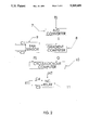
- FIG. 1 is a diagram showing the invention and its electrical connections to the heating components of a recreational vehicle or the like;
- FIG. 2 is a block diagram of the invention shown in FIG. 1;
- FIG. 3 is a segmented circuit diagram of the Fan Sensor shown in FIG. 2;
- FIG. 4 is a block diagram of the Gradient Computer shown in FIG. 2;
- FIG. 5 is a block diagram of the Cycle/Lockout computer shown in FIG. 2.
- FIG. 6 is a diagram showing a typical RV propane supply system and its interface with the pressure sensor, furnace, and central panel shown in FIG. 1.
- FIG. 1 the preferred embodiment of the invention is shown electrically connected to the typical heating components of a recreational vehicle or marine vessel or the like.
- the details of the internal operation of the furnace and its components is not central to the invention and as such the furnace will not be described beyond characterization of its interface to the invention. What will be described first is the manner in which the electrical connections of the invention, the Central Instrumentation and Control Panel 3 of FIG. 1, are made so as to present the invention in series between the power supply or battery and the furnace and simultaneously in series between the furnace and thermostat.
- the battery or battery system is represented by Power Supply 4.
- the furnace 1 is normally electrically powered by direct connection to the power supply, with the electrical contact F- of the furnace connected directly to the negative terminal of the power supply, as shown in FIG. 1.
- the electrical contact F+ of the furnace which is normally connected to the positive terminal of the power supply is instead, in the preferred embodiment of the invention, connected to the electrical contact C1 of said central instrumentation and control panel 3 in the figure.
- the positive terminal of the power supply 4 is then connected to the electrical contact C2 of the invention as shown in the figure. In this manner the current which normally flows from power supply 4 to the furnace 1 passes through the preferred embodiment of the invention. In this way, flow of current to the furnace can be sensed by the invention, the details of which will be described later.
- the thermostat presents an open circuit of infinite resistance when the cabin environment temperature of the recreational vehicle is greater than the demanded temperature setting of the thermostat, or a closed circuit of zero resistance when the cabin environment temperature is less than the demanded temperature setting of the thermostat. In this manner, the thermostat signals to the furnace or calls for heat by presenting an open or short circuit.
- the thermostat 2 which is normally connected across the electrical contacts T1 and T2 of the furnace 1, is instead in the preferred embodiment of the invention connected in series with said central panel 3 by connecting one end of the thermostat 2 to electrical contact T1 of the furnace and the other to electrical contact C4 of the central panel. Electrical contact C3 of the central panel is connected to the contact T2 of the furnace 1. In this way, a short circuit presented to the furnace by the thermostat can be opened or interrupted, the details of which will be described later, thereby turning off the furnace.
- the thermal sensor 5 of the preferred embodiment of the invention provides an analog voltage first signal TS indicative of vehicle cabin temperature to the central panel.
- a temperature transmitter can be used which provides a small current, typically 4 to 20 milliamperes in many commercially available transmitters.
- a shunt resistor could then be suitably employed to provide an analog voltage signal indicative of the vehicle cabin temperature.
- a commercially available IC integrated circuit
- the pressure sensor 6 of the preferred embodiment of the invention provides an analog voltage signal PS indicative of the propane gas pressure as delivered to the gas furnace of the RV. Details of the pressure sensor and the propane supply system will be described later.
- the signal PS is displayed at the centrally located panel to provide remote indication and diagnostic capability. When the signal falls below a setpoint, an alarm is energized to provide indication to the RV occupants of low propane gas pressure. A second setpoint can also be used such that when the signal rises above it, a second alarm is energized providing indication of high gas pressure.
- a pressure transmitter can be used which provides a small current, typically 4 to 20 milliamperes in many commercially available transmitters.
- a shunt resistor could then be suitably employed to provide an analog voltage signal indicative of the propane gas pressure.
- Alarm setpoint operations are included in such commercially available transmitters, as well as various indication meters in the art.
- a commercially available analog to digital (A/D) IC integrated circuit
- A/D analog to digital
- IC integrated circuit
- the analog signal TS from the temperature sensor previously described is applied to an analog to digital (A/D) converter 7 to produce the digital signal T indicative of temperature.
- the signal T is then input to the Gradient Computer 8 which computes a second signal, the thermal gradient with respect to time, the details of which are described later. If the temperature is decreasing over time, the gradient third signal G is output ON or high from the gradient computer and applied to the Cycle/Lockout Computer 10.
- the Fan Sensor 9 detects the operation of the fan or blower motor in the furnace from the current being drawn by the furnace through terminals C2 and C1, and outputs the fan sensor fourth signal FS high or ON if fan operation is detected, the details of which are described later.
- the fan sensor signal FS as well as the gradient signal GS are both input to said Cycle/Lockout Computer 10. If the gradient signal G and the fan sensor signal FS are both high, indicating the furnace fan is on yet the temperature is decreasing, the cycle/lockout computer performs actions to correct the probable scenario that the furnace has failed to ignite and is blowing cold air. If the corrective actions have not been effective three times since a reset then the assumption is made the furnace will not fire due to lack of fuel or low voltage from the battery or some other malfunction and will lock out the furnace from attempting to ignite again, the details of which are to be described later. If the recycle/lockout computer determines the furnace has not ignited and is blowing cold air, it outputs the pulsed interrupt signal INT which is applied to the coil of normally closed (NC) relay 11.
- NC normally closed
- the cycle/lockout computer can cycle the furnace if the thermostat is on (i.e., calling for heat) by opening and reclosing the circuit by pulsing the interrupt signal INT. If the furnace fails to ignite after three such cycling actions, it can be turned off or locked out by the cycle/lockout computer by setting the interrupt signal INT high or ON. Details of the cycle/lockout computer will be described later.
- fan sensor referenced previously in prior FIG. 2 will be described.
- the current drawn by the furnace when in operation and powered by vehicle voltages of twelve volts is typically about five to ten amperes, most of the current being supplied to the fan or blower of the furnace.
- the method of sensing this fan current will now be described.
- the current to be sensed fan current IF flows from terminal C2 to terminal C1 in the figure.
- the current flows through sense resistor RS, producing a sensed voltage drop VS across it.
- the sensed voltage VS due to furnace current is then applied to a buffer amplifier formed by operational amplifier 15 with input resistor R1 connected to its non-inverting input and feedback resistor RF connected from the output at node 14 to its non-inverting input as shown in the figure. Power supply connections are understood and not shown.
- the sensed voltage VS is then applied across nodes 12 and 13, producing an output voltage VO at the output node 14. If no current is drawn by the furnace, the sense voltage VS is zero and the output voltage VO of said operational amplifier 15 will then be equal to the cabin power supply voltage supplied to the furnace at C2, normally twelve volts.
- the output VO will be equal to the cabin power supply voltage plus the sense voltage multiplied by the gain of the amplifier stage which in the preferred embodiment here is RF/R1.
- This output voltage is applied to the non-inverting input at node 14 of comparator 17, and a reference voltage VREF is applied to the inverting input at node 16 of the comparator.
- the reference voltage VREF may be preferably set to the cabin power supply voltage supplied to the furnace at C2.
- the comparator output, signal FS will then swing to the positive supply voltage +VCC, which is preferably a digital logic level in the preferred embodiment. In this manner, the digital fan sensor signal FS is output high when the furnace fan is on and drawing current.
- VCC positive supply voltage
- Other similar means of detecting the current draw may be employed, such as utilizing transistors or Darlington transistor pairs instead of operational amplifiers, employing commercially available integrated circuit Schmitt triggers instead of comparators, or augmenting the circuit described here in the preferred embodiment with hysteresis feedback paths and such.
- Various other methods of sensing current alternative to the preferred embodiment will no doubt occur to those skilled in the art, for example utilizing a commercially available current sensor known as a Hall sensor which is responsive to the magnetic field associated with current flow.
- the digital signal T previously described as the output from the analog to digital converter of prior FIG. 2 is used to detect a decrease in the vehicle's cabin environment temperature in the embodiment by digital logic.
- the signal T is delayed by delay block 18 and stored in a buffer register as signal T1.
- the signal T1 is delayed by delay block 19 and the result stored in a buffer register as the twice delayed signal T2
- the signal T2 is delayed by delay block 20 and the result stored in a buffer register as the thrice delayed signal T3.
- the signal T and the delayed signal T1 are input to a subtractor 21 so as to form the differential signal G1 such that the value of G1 is equal to the value of T minus the value of T1, making the value of G1 positive if the temperature signal is decreasing over time in decrements at least as large as the least significant bit (LSB) of the A/D converter.
- the differential signal G2 is formed by the subtraction of T2 from T1 and the differential signal G3 is formed by the subtraction of T3 from T2.
- the outputs Y1, Y2, and Y3 are therefore set one or high if the temperature differential signals G1, G2, and G3 are positive which indicates a decreasing temperature, indicative of the cabin environment becoming colder.
- the carry bit from the prior subtraction could be output directly or passed through a buffer or flip-flop, or the temperature signals fed to the inverting and non-inverting inputs of a comparator to produce the appropriate signals at the comparator outputs.
- various arrangements of J-K, R-S, and other flip-flops can be utilized to produce the signals Y1, Y2, and Y3.
- the signals Y1, Y2, and Y3 are all input to AND gate 23 to produce the output signal G which will energized to high when a decrease in temperature is detected.
- the gradient signal G thus requires three successive decreases in temperature to indicate a negative thermal gradient, so as to average out spurious noise effects in the measurement of the temperature signal.
- the fan sensor signal FS and the gradient signal G are both input to the AND gate 24 which produces the output logic fifth signal CA. If the gradient signal G and the fan sensor signal FS are both high or ON, indicating the furnace fan is on yet the temperature is decreasing meaning that the furnace has failed to ignite and is blowing cold air, said AND gate 24 outputs the corrective action signal CA high or ON.
- the signal CA is applied to counter block 25 to increment the counter signal NCA representing the number of times corrective action has been necessary. Counter signal NCA is resettable to zero as shown by block 26.
- momentary switch 27 preferably located on the central control panel of the preferred embodiment, resets counter signal NCA by setting a clear line of the counter logically high to the appropriate logic level voltage supply +VS.
- the counter signal NCA is applied to NCA display array 28 which is preferably an array of three indicators such as light emitting diodes (LEDs), thereby informing the user how many times corrective action was required.
- the counter signal NCA is also applied to decision block 29. If counter signal NCA is not greater than three, the cycle timer 30 is turned on which provides at its output a pulsed cycle signal C which goes high or ON for a preset length of time before returning to low or OFF. Said cycle signal C is also applied to the cycle display 31, preferably an LED, providing indication of the cycling action in progress.
- the lockout sixth signal LO is set high or ON and applied to the lockout display 32, preferably an LED, providing indication of such lockout condition.
- the lockout signal LO is applied to the input of OR gate 33, along with the cycle signal C.
- the output of said OR gate, interrupt signal INT, is high or ON when either lockout signal LO is ON or cycle signal C is ON.
- the interrupt signal INT effectively turns the furnace off when it is high, and therefore the furnace--thermostat circuit is subject to the corrective action when necessary of being cycled off and then on by the pulsed cycle signal C or ultimately being turned off by lockout signal LO.
- An LPG supply tank 34 stores the LPG in a liquid form under high pressure.
- a valve 35 often referred to in the art as a POL valve, is installed in the tank to allow shutoff of the LPG flow. Details of safety valves, overfill valves and other such normally installed devices are not central to the operation described herein and are therefore not shown in the figure.
- a pressure regulator 36 is typically installed at or near the supply tank an is in pneumatic communication with the outlet of said valve 35 by fittings or line 41. Said regulator provides at its outlet propane gas at a relatively low pressure and is in pneumatic communication with one end of supply line 42, normally copper tubing.
- the other end of supply line 42 is in pneumatic communication with one port of pressure sensor 6, previously shown in prior FIG. 1 with regard to electrical signal communication.
- the other port of said pressure sensor is in pneumatic communication with supply line 40 such that propane gas flows from the pressure regulator through the pressure sensor to Tee-fitting 37.
- a second port of said Tee-fitting is in pneumatic communication with supply line 38 and allows propane gas flow to the Furnace 1, previously shown in prior FIG. 1 with regard to electrical signal communication.
- a third port of said Tee-fitting is in pneumatic communication with supply line 39 and allows propane gas flow to all other RV propane fueled appliances, not shown but understood to be downstream of port A in the figure. Other details and variations of RV propane installations not central to the invention and its preferred embodiment are not shown. As previously described in FIG.
- the pressure sensor 6 provides the electrical signal P$ responsive to the propane pressure to the central panel.
- the signal PS is input to instrumentation amplifier 43 which outputs the signal P conditioned to drive display meter 44, providing visual indication of the propane gas pressure as delivered to the furnace and other RV appliances.
- An alarm setpoint output signal AL from said meter 44 is used to energize alarm 45, a visual indicator such as an LED, preferably located at the central panel. Said alarm output is generated by a low setpoint function when the signal P falls below a reference value corresponding to the minimum recommended gas pressure.
- a second high setpoint function can also be similarly used to energized a second alarm to indicate high gas pressure.
- the instrumentation amplifier can be replaced by an analog to digital (A/D) converter and its output used to drive a digital panel meter (DPM), such DPM's being commercially available with and without the alarm setpoint functions described above.
- DPM digital panel meter
- the alarm setpoint functions described can be implemented by comparison to reference voltages and the alarm signal AL generated at the output of a comparator.
Abstract
Description
Claims (8)
Priority Applications (1)
| Application Number | Priority Date | Filing Date | Title |
|---|---|---|---|
| US08/004,268 US5269458A (en) | 1993-01-14 | 1993-01-14 | Furnace monitoring and thermostat cycling system for recreational vehicles and marine vessels |
Applications Claiming Priority (1)
| Application Number | Priority Date | Filing Date | Title |
|---|---|---|---|
| US08/004,268 US5269458A (en) | 1993-01-14 | 1993-01-14 | Furnace monitoring and thermostat cycling system for recreational vehicles and marine vessels |
Publications (1)
| Publication Number | Publication Date |
|---|---|
| US5269458A true US5269458A (en) | 1993-12-14 |
Family
ID=21709970
Family Applications (1)
| Application Number | Title | Priority Date | Filing Date |
|---|---|---|---|
| US08/004,268 Expired - Fee Related US5269458A (en) | 1993-01-14 | 1993-01-14 | Furnace monitoring and thermostat cycling system for recreational vehicles and marine vessels |
Country Status (1)
| Country | Link |
|---|---|
| US (1) | US5269458A (en) |
Cited By (27)
| Publication number | Priority date | Publication date | Assignee | Title |
|---|---|---|---|---|
| US6535838B2 (en) | 2000-01-28 | 2003-03-18 | Robertshaw Controls Company | Furnace diagnostic system |
| US20030085021A1 (en) * | 2001-08-17 | 2003-05-08 | Dykes Ronald M. | Energy optimizer |
| US20040007196A1 (en) * | 2002-07-15 | 2004-01-15 | Jonathan Young | Vehicle heater and controls therefor |
| US20040145324A1 (en) * | 2003-01-28 | 2004-07-29 | Ross Christian E. | Integrated control device for environmental systems |
| EP1610062A3 (en) * | 2004-06-25 | 2008-03-26 | J. Eberspächer GmbH Co. KG | Heating device for a vehicle and method to operate said device |
| US20080304199A1 (en) * | 2007-06-07 | 2008-12-11 | Black & Decker Inc. | Software-implemented overcurrent protection embedded in a battery pack |
| US20090039070A1 (en) * | 2007-08-06 | 2009-02-12 | Jung-Wen Tseng | Semiconductor equipment and breakdown precautionary system and method thereof |
| US7784705B2 (en) | 2006-02-27 | 2010-08-31 | Honeywell International Inc. | Controller with dynamic temperature compensation |
| US8949066B2 (en) | 2007-12-04 | 2015-02-03 | Honeywell International Inc. | System for determining ambient temperature |
| US8964338B2 (en) | 2012-01-11 | 2015-02-24 | Emerson Climate Technologies, Inc. | System and method for compressor motor protection |
| US8974573B2 (en) | 2004-08-11 | 2015-03-10 | Emerson Climate Technologies, Inc. | Method and apparatus for monitoring a refrigeration-cycle system |
| US9121407B2 (en) | 2004-04-27 | 2015-09-01 | Emerson Climate Technologies, Inc. | Compressor diagnostic and protection system and method |
| US9140728B2 (en) | 2007-11-02 | 2015-09-22 | Emerson Climate Technologies, Inc. | Compressor sensor module |
| CN104950864A (en) * | 2014-03-26 | 2015-09-30 | 成都凯天电子股份有限公司 | Method for performing online detection on characteristic of ice-preventing system of aircraft engine |
| US9285802B2 (en) | 2011-02-28 | 2016-03-15 | Emerson Electric Co. | Residential solutions HVAC monitoring and diagnosis |
| US9310439B2 (en) | 2012-09-25 | 2016-04-12 | Emerson Climate Technologies, Inc. | Compressor having a control and diagnostic module |
| US9310094B2 (en) | 2007-07-30 | 2016-04-12 | Emerson Climate Technologies, Inc. | Portable method and apparatus for monitoring refrigerant-cycle systems |
| US9335769B2 (en) | 2007-12-04 | 2016-05-10 | Honeywell International Inc. | System for determining ambient temperature |
| US9534782B2 (en) | 2014-10-30 | 2017-01-03 | Falcon Road Maintenance Equipment | Burner unit having a low voltage sensor |
| US9551504B2 (en) | 2013-03-15 | 2017-01-24 | Emerson Electric Co. | HVAC system remote monitoring and diagnosis |
| US9638436B2 (en) | 2013-03-15 | 2017-05-02 | Emerson Electric Co. | HVAC system remote monitoring and diagnosis |
| US9765979B2 (en) | 2013-04-05 | 2017-09-19 | Emerson Climate Technologies, Inc. | Heat-pump system with refrigerant charge diagnostics |
| US9797619B2 (en) | 2013-03-15 | 2017-10-24 | Honeywell International Inc. | Temperature compensation system for an electronic device |
| US9803902B2 (en) | 2013-03-15 | 2017-10-31 | Emerson Climate Technologies, Inc. | System for refrigerant charge verification using two condenser coil temperatures |
| US9823632B2 (en) | 2006-09-07 | 2017-11-21 | Emerson Climate Technologies, Inc. | Compressor data module |
| US9885507B2 (en) | 2006-07-19 | 2018-02-06 | Emerson Climate Technologies, Inc. | Protection and diagnostic module for a refrigeration system |
| US20220348056A1 (en) * | 2021-04-30 | 2022-11-03 | Haier Us Appliance Solutions, Inc. | Universal control for recreational vehicle air conditioner |
Citations (2)
| Publication number | Priority date | Publication date | Assignee | Title |
|---|---|---|---|---|
| US4951870A (en) * | 1990-02-21 | 1990-08-28 | Carrier Corporation | Overtemperature control |
| US4978292A (en) * | 1989-02-27 | 1990-12-18 | Emerson Electric Co. | Fuel burner control system with hot surface ignition |
-
1993
- 1993-01-14 US US08/004,268 patent/US5269458A/en not_active Expired - Fee Related
Patent Citations (2)
| Publication number | Priority date | Publication date | Assignee | Title |
|---|---|---|---|---|
| US4978292A (en) * | 1989-02-27 | 1990-12-18 | Emerson Electric Co. | Fuel burner control system with hot surface ignition |
| US4951870A (en) * | 1990-02-21 | 1990-08-28 | Carrier Corporation | Overtemperature control |
Cited By (69)
| Publication number | Priority date | Publication date | Assignee | Title |
|---|---|---|---|---|
| US6535838B2 (en) | 2000-01-28 | 2003-03-18 | Robertshaw Controls Company | Furnace diagnostic system |
| US6658372B2 (en) | 2000-01-28 | 2003-12-02 | Robertshaw Controls Company | Furnace diagnostic system |
| US20030085021A1 (en) * | 2001-08-17 | 2003-05-08 | Dykes Ronald M. | Energy optimizer |
| US20050039715A1 (en) * | 2002-07-15 | 2005-02-24 | Jonathan Young | Vehicle heater and controls therefor |
| US20050039716A1 (en) * | 2002-07-15 | 2005-02-24 | Jonathan Young | Vehicle heater and controls therefor |
| US20060191498A1 (en) * | 2002-07-15 | 2006-08-31 | Teleflex Canada Limited Partnership | Vehicle heater and controls therefor |
| US7270098B2 (en) * | 2002-07-15 | 2007-09-18 | Teleflex Canada Inc. | Vehicle heater and controls therefor |
| US9428036B2 (en) | 2002-07-15 | 2016-08-30 | Teleflex Canada Limited Partnership | Vehicle heaters and controls therefor |
| US20040007196A1 (en) * | 2002-07-15 | 2004-01-15 | Jonathan Young | Vehicle heater and controls therefor |
| US7597552B2 (en) | 2002-07-15 | 2009-10-06 | Teleflex Canada Inc. | Vehicle heater and controls therefor |
| US20100170954A1 (en) * | 2002-07-15 | 2010-07-08 | Jonathan Young | Vehicle heaters and controls therefor |
| US20040145324A1 (en) * | 2003-01-28 | 2004-07-29 | Ross Christian E. | Integrated control device for environmental systems |
| US9121407B2 (en) | 2004-04-27 | 2015-09-01 | Emerson Climate Technologies, Inc. | Compressor diagnostic and protection system and method |
| US9669498B2 (en) | 2004-04-27 | 2017-06-06 | Emerson Climate Technologies, Inc. | Compressor diagnostic and protection system and method |
| US10335906B2 (en) | 2004-04-27 | 2019-07-02 | Emerson Climate Technologies, Inc. | Compressor diagnostic and protection system and method |
| EP1610062A3 (en) * | 2004-06-25 | 2008-03-26 | J. Eberspächer GmbH Co. KG | Heating device for a vehicle and method to operate said device |
| US9690307B2 (en) | 2004-08-11 | 2017-06-27 | Emerson Climate Technologies, Inc. | Method and apparatus for monitoring refrigeration-cycle systems |
| US8974573B2 (en) | 2004-08-11 | 2015-03-10 | Emerson Climate Technologies, Inc. | Method and apparatus for monitoring a refrigeration-cycle system |
| US9017461B2 (en) | 2004-08-11 | 2015-04-28 | Emerson Climate Technologies, Inc. | Method and apparatus for monitoring a refrigeration-cycle system |
| US9023136B2 (en) | 2004-08-11 | 2015-05-05 | Emerson Climate Technologies, Inc. | Method and apparatus for monitoring a refrigeration-cycle system |
| US9021819B2 (en) | 2004-08-11 | 2015-05-05 | Emerson Climate Technologies, Inc. | Method and apparatus for monitoring a refrigeration-cycle system |
| US9046900B2 (en) | 2004-08-11 | 2015-06-02 | Emerson Climate Technologies, Inc. | Method and apparatus for monitoring refrigeration-cycle systems |
| US9081394B2 (en) | 2004-08-11 | 2015-07-14 | Emerson Climate Technologies, Inc. | Method and apparatus for monitoring a refrigeration-cycle system |
| US9086704B2 (en) | 2004-08-11 | 2015-07-21 | Emerson Climate Technologies, Inc. | Method and apparatus for monitoring a refrigeration-cycle system |
| US10558229B2 (en) | 2004-08-11 | 2020-02-11 | Emerson Climate Technologies Inc. | Method and apparatus for monitoring refrigeration-cycle systems |
| US9304521B2 (en) | 2004-08-11 | 2016-04-05 | Emerson Climate Technologies, Inc. | Air filter monitoring system |
| US7784705B2 (en) | 2006-02-27 | 2010-08-31 | Honeywell International Inc. | Controller with dynamic temperature compensation |
| US9885507B2 (en) | 2006-07-19 | 2018-02-06 | Emerson Climate Technologies, Inc. | Protection and diagnostic module for a refrigeration system |
| US9823632B2 (en) | 2006-09-07 | 2017-11-21 | Emerson Climate Technologies, Inc. | Compressor data module |
| US20080304199A1 (en) * | 2007-06-07 | 2008-12-11 | Black & Decker Inc. | Software-implemented overcurrent protection embedded in a battery pack |
| US9310094B2 (en) | 2007-07-30 | 2016-04-12 | Emerson Climate Technologies, Inc. | Portable method and apparatus for monitoring refrigerant-cycle systems |
| US10352602B2 (en) | 2007-07-30 | 2019-07-16 | Emerson Climate Technologies, Inc. | Portable method and apparatus for monitoring refrigerant-cycle systems |
| US20090039070A1 (en) * | 2007-08-06 | 2009-02-12 | Jung-Wen Tseng | Semiconductor equipment and breakdown precautionary system and method thereof |
| US9194894B2 (en) | 2007-11-02 | 2015-11-24 | Emerson Climate Technologies, Inc. | Compressor sensor module |
| US9140728B2 (en) | 2007-11-02 | 2015-09-22 | Emerson Climate Technologies, Inc. | Compressor sensor module |
| US10458404B2 (en) | 2007-11-02 | 2019-10-29 | Emerson Climate Technologies, Inc. | Compressor sensor module |
| US9335769B2 (en) | 2007-12-04 | 2016-05-10 | Honeywell International Inc. | System for determining ambient temperature |
| US8949066B2 (en) | 2007-12-04 | 2015-02-03 | Honeywell International Inc. | System for determining ambient temperature |
| US10154541B2 (en) | 2007-12-04 | 2018-12-11 | Honeywell International Inc. | System for determining ambient temperature |
| US10805987B2 (en) | 2007-12-04 | 2020-10-13 | Ademco Inc. | System for determining ambient temperature |
| US8954288B2 (en) | 2007-12-04 | 2015-02-10 | Honeywell International Inc. | System for determining ambient temperature |
| US9345066B2 (en) | 2007-12-04 | 2016-05-17 | Honeywell International Inc. | System for determining ambient temperature |
| US9326323B2 (en) | 2007-12-04 | 2016-04-26 | Honeywell International Inc. | System for determining ambient temperature |
| US10222271B2 (en) | 2007-12-04 | 2019-03-05 | Ademco Inc. | System for determining ambient temperature |
| US10884403B2 (en) | 2011-02-28 | 2021-01-05 | Emerson Electric Co. | Remote HVAC monitoring and diagnosis |
| US9703287B2 (en) | 2011-02-28 | 2017-07-11 | Emerson Electric Co. | Remote HVAC monitoring and diagnosis |
| US10234854B2 (en) | 2011-02-28 | 2019-03-19 | Emerson Electric Co. | Remote HVAC monitoring and diagnosis |
| US9285802B2 (en) | 2011-02-28 | 2016-03-15 | Emerson Electric Co. | Residential solutions HVAC monitoring and diagnosis |
| US9876346B2 (en) | 2012-01-11 | 2018-01-23 | Emerson Climate Technologies, Inc. | System and method for compressor motor protection |
| US9590413B2 (en) | 2012-01-11 | 2017-03-07 | Emerson Climate Technologies, Inc. | System and method for compressor motor protection |
| US8964338B2 (en) | 2012-01-11 | 2015-02-24 | Emerson Climate Technologies, Inc. | System and method for compressor motor protection |
| US9762168B2 (en) | 2012-09-25 | 2017-09-12 | Emerson Climate Technologies, Inc. | Compressor having a control and diagnostic module |
| US9310439B2 (en) | 2012-09-25 | 2016-04-12 | Emerson Climate Technologies, Inc. | Compressor having a control and diagnostic module |
| US9803902B2 (en) | 2013-03-15 | 2017-10-31 | Emerson Climate Technologies, Inc. | System for refrigerant charge verification using two condenser coil temperatures |
| US10775084B2 (en) | 2013-03-15 | 2020-09-15 | Emerson Climate Technologies, Inc. | System for refrigerant charge verification |
| US9797619B2 (en) | 2013-03-15 | 2017-10-24 | Honeywell International Inc. | Temperature compensation system for an electronic device |
| US9638436B2 (en) | 2013-03-15 | 2017-05-02 | Emerson Electric Co. | HVAC system remote monitoring and diagnosis |
| US10274945B2 (en) | 2013-03-15 | 2019-04-30 | Emerson Electric Co. | HVAC system remote monitoring and diagnosis |
| US10488090B2 (en) | 2013-03-15 | 2019-11-26 | Emerson Climate Technologies, Inc. | System for refrigerant charge verification |
| US9551504B2 (en) | 2013-03-15 | 2017-01-24 | Emerson Electric Co. | HVAC system remote monitoring and diagnosis |
| US9765979B2 (en) | 2013-04-05 | 2017-09-19 | Emerson Climate Technologies, Inc. | Heat-pump system with refrigerant charge diagnostics |
| US10443863B2 (en) | 2013-04-05 | 2019-10-15 | Emerson Climate Technologies, Inc. | Method of monitoring charge condition of heat pump system |
| US10060636B2 (en) | 2013-04-05 | 2018-08-28 | Emerson Climate Technologies, Inc. | Heat pump system with refrigerant charge diagnostics |
| CN104950864A (en) * | 2014-03-26 | 2015-09-30 | 成都凯天电子股份有限公司 | Method for performing online detection on characteristic of ice-preventing system of aircraft engine |
| CN104950864B (en) * | 2014-03-26 | 2018-06-05 | 成都凯天电子股份有限公司 | The method of on-line checking aircraft engine anti-icing system characteristic |
| US10041214B2 (en) | 2014-10-30 | 2018-08-07 | Falcon Road Maintenance Equipment | Burner unit having a low voltage sensor |
| US9534782B2 (en) | 2014-10-30 | 2017-01-03 | Falcon Road Maintenance Equipment | Burner unit having a low voltage sensor |
| US20220348056A1 (en) * | 2021-04-30 | 2022-11-03 | Haier Us Appliance Solutions, Inc. | Universal control for recreational vehicle air conditioner |
| US11691475B2 (en) * | 2021-04-30 | 2023-07-04 | Haier Us Appliance Solutions, Inc. | Universal control for recreational vehicle air conditioner |
Similar Documents
| Publication | Publication Date | Title |
|---|---|---|
| US5269458A (en) | Furnace monitoring and thermostat cycling system for recreational vehicles and marine vessels | |
| US8740101B2 (en) | Backup control for HVAC system | |
| US6728600B1 (en) | Distributed appliance control system having fault isolation | |
| US4381549A (en) | Automatic fault diagnostic apparatus for a heat pump air conditioning system | |
| US4352349A (en) | Control circuit for air conditioning systems | |
| US7089088B2 (en) | Integrated HVACR control and protection system | |
| US5557938A (en) | Transport refrigeration unit and method of operating same | |
| US4449375A (en) | Method and apparatus for controlling the operation of an indoor fan associated with an air conditioning unit | |
| US8485137B2 (en) | Combustion control device | |
| US8333584B2 (en) | Burner control | |
| KR950023929A (en) | How the heat pump system works and how to deal with detector errors | |
| US5419358A (en) | Gas monitoring system for a boiler | |
| US5490556A (en) | Off-road air conditioning control | |
| CA2182240C (en) | Transit vehicle heater | |
| US6731098B1 (en) | Method and apparatus for sensing variable currents within the alternator of a genset that employs an amplifier and a switched feedback resistance | |
| US11549708B2 (en) | Systems and methods for checking status of a pressure transducer | |
| US20210268871A1 (en) | Control system for hydronic heater and method of operating same | |
| US4851822A (en) | Electronic monitoring system | |
| US4493194A (en) | Apparatus for controlling the operation of an indoor fan associated with an air conditioning unit | |
| US5648722A (en) | Apparatus and method for determining the state of an electrical switch within an HVAC system | |
| EP3957503B1 (en) | Closed loop feedback control and diagnostics of a transport climate control system | |
| US11635220B2 (en) | Systems and methods for checking status of a pressure transducer | |
| US5863194A (en) | Interrogation of multiple switch conditions | |
| US4757693A (en) | Air conditioning system for a motor vehicle | |
| US10352588B2 (en) | Systems and methods for controlling gas powered appliances |
Legal Events
| Date | Code | Title | Description |
|---|---|---|---|
| REMI | Maintenance fee reminder mailed | ||
| LAPS | Lapse for failure to pay maintenance fees | ||
| FP | Expired due to failure to pay maintenance fee |
Effective date: 19971217 |
|
| AS | Assignment |
Owner name: DCI HOLDINGS, INC., OHIO Free format text: ASSIGNMENT OF ASSIGNORS INTEREST;ASSIGNOR:LACH, ROBERT L.;REEL/FRAME:010609/0793 Effective date: 20000114 Owner name: LACH, ROBERT L., MASSACHUSETTS Free format text: ASSIGNMENT OF ASSIGNORS INTEREST;ASSIGNOR:NEW CREATIVE ENTERPRISES, INC.;REEL/FRAME:010609/0795 Effective date: 19980415 |
|
| AS | Assignment |
Owner name: DCI HOLDINGS, INC., OHIO Free format text: ASSIGNMENT OF ASSIGNORS INTEREST;ASSIGNOR:LACH, ROBERT L.;REEL/FRAME:011485/0924 Effective date: 20000114 |
|
| STCH | Information on status: patent discontinuation |
Free format text: PATENT EXPIRED DUE TO NONPAYMENT OF MAINTENANCE FEES UNDER 37 CFR 1.362 |