US525977A - darrach - Google Patents
darrach Download PDFInfo
- Publication number
- US525977A US525977A US525977DA US525977A US 525977 A US525977 A US 525977A US 525977D A US525977D A US 525977DA US 525977 A US525977 A US 525977A
- Authority
- US
- United States
- Prior art keywords
- fender
- springs
- car
- scoop
- spring
- Prior art date
- Legal status (The legal status is an assumption and is not a legal conclusion. Google has not performed a legal analysis and makes no representation as to the accuracy of the status listed.)
- Expired - Lifetime
Links
- 230000000994 depressogenic effect Effects 0.000 description 3
- 238000010276 construction Methods 0.000 description 1
- 230000004048 modification Effects 0.000 description 1
- 238000012986 modification Methods 0.000 description 1
- 238000005096 rolling process Methods 0.000 description 1
Images

Classifications
-
- B—PERFORMING OPERATIONS; TRANSPORTING
- B61—RAILWAYS
- B61F—RAIL VEHICLE SUSPENSIONS, e.g. UNDERFRAMES, BOGIES OR ARRANGEMENTS OF WHEEL AXLES; RAIL VEHICLES FOR USE ON TRACKS OF DIFFERENT WIDTH; PREVENTING DERAILING OF RAIL VEHICLES; WHEEL GUARDS, OBSTRUCTION REMOVERS OR THE LIKE FOR RAIL VEHICLES
- B61F19/00—Wheel guards; Bumpers; Obstruction removers or the like
- B61F19/06—Nets, catchers, or the like for catching obstacles or removing them from the track
Definitions
- This invention relates to an improvement in car fenders and the object of the invention is to take up persons on the fender, and also prevent persons who may have fallen or slipped under the fender from being injured by the car body or the car wheels.
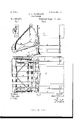
- FIG. 1 is a side elevation of the fender.
- Fig. 2 is a plan view of Fig. 1.
- Fig. 3 isa sect on along a;
- Fig. 4 is a side elevation of a modification.
- Fig. 5 is an inverted plan view of Fig. 4.
- Fig. 6 is a section along y y Fig. 4.
- the letter A indicates a car platform; B, the dash board, and C the From the dash board extend hangers D strengthened by braces E and hangers F.
- the hangers D have pockets or attachments G for the engagement of arms H carrying a pivot or barI supporting the swinging spring strips or bands K to which at L are jointed the spring strips or bands M.
- the spring set M at its outer or free end has a spring strip or connection N and the springs or yielding guards 0 extending from strip Nto bar I form an additional protection for a person while allowing the free end of spring set M to be raised or pushed up by any object or body falling or rolling underneath the springs M.
- the spring set M is provided with a cross bar Pto which are secured braces Q, said braces being jointed to bar R.
- the bar R is shown connected to hangers S extending from arms H and steadied by a suitable fastening on hanger D, such as an eye and pin connection T U.
- a suitable fastening on hanger D such as an eye and pin connection T U.
- the bar R is shown secured to hangers D and the brace Q has hooks X slipping or sitting onto bar R and held in place by a suitable fastening or attachment such as a spring pressed hook V engaging a shoulder W.
- the brace Q will prevent the free end or portion of spring set M from being forced backward by an impact, while the spring sets M K with the spring connection N will cause the victim when struck by the fender to receive ayielding blow, and to have his fall eased when landing on the spring sets M K.
- a scoop composed of arms Y carrying spring fingers or strips Z.
- the arms Y are provided with a cross piece a at their rear portion said rear portion being intended to rest on a ledge or shoulder b on hanger D so that while the car is running the springs Z will be kept clear of the ground as seen in dotted lines in Figs. 1 and 4.
- the springs Z at their free ends have a rope the scoop with its springs or fingers Z to the ground.
- the pawl 6 being released by hand the scoop Y Z can be lifted and its free portion replaced on ledge 19.
- the cord or rope c forming a flexible connection for the free ends of springs Z will allow said springs severally to follow the inequalities of the ground, and by placing flexible rollers or coiled spring sections g (Fig. 2 on the cord 0 between the fingers or springs Z the fingers will be enabled to ride easily over the ground.
- the rollers g formed of coiled spring sections as in Fig. 2,
- rubber tube sections g as seen in Fig. 5 can be made to form the elastic rollers on the cord or connection a.
- a car fender composed of two sections as K M jointed together and provided with a scoop jointed to one of the sections and adapted to be depressed or dipped by the swinging of said last named. section substantially as described.
- a car fender provided with a scoop jointed to the fender and adapted to be de' pressed or dipped by the swinging of the fender, and a detent or look as e for holding the scoop depressed substantially as described.
- a car fender provided with a scoop jointed to the fender and adapted to be depressed or dipped by the swinging of the fender, said scoop being provided with spring fingers as Z having their free ends joined by a flexible connection as c substantially as de scribed.
- a car fender provided with a scoop, said scoop being provided with spring fingers as
Landscapes
- Engineering & Computer Science (AREA)
- Mechanical Engineering (AREA)
- Body Structure For Vehicles (AREA)
Description
(No Model.) 2 Sheets-Sheet 1.
S. A. DARRAUH.
GAB. FENDER.
No. 525,977. Patented Sept. 11, 1894.
WPY% A1. ATTORNEYS.
(No Model.) 2 SIIGGiZSw-Shfl 2.
s. A. DARRACH.
GAR FENDER.
No. 525,977. Patented Sept. 11. 1894.
WH NESSES: NVENTOR:
5 (s mmlflflarmd ATTORNEYS.
- SAMUEL ADGER DARRAOl-I, OF NEWARK, NEW JERSEY, ASSIGN OR TO steps.
UNITED STATES P TENT OFFICE.
' DARRACH OAR-FENDER COMPANY, OF SAME PLACE.
CAR-FENDER.
SPECIFICATION forming part of Letters Iatent No. 525,977, dated September 11, 1894.
Application filed January 11, 1894. Serial No. 496,491. (No model.)
To alt whom it may concern:
Be 1t known that I, SAMUEL ADGER DAB- RAOH, a cltizen of the United States, residing at Newark, in the county of Essex andState of,
New Jersey, have invented new and useful Improvements in Oar-Fenders, of which the following is a specification.
This invention relates to an improvement in car fenders and the object of the invention is to take up persons on the fender, and also prevent persons who may have fallen or slipped under the fender from being injured by the car body or the car wheels.
To accomplish this obj ect my invention consists in the features of construction and the eombination'or arrangement of parts herenafter described and claimed, reference being made to the accompanying drawings, in which i Figure 1 is a side elevation of the fender. Fig. 2 is a plan view of Fig. 1. Fig. 3 isa sect on along a; Fig. 1. Fig. 4 is a side elevation of a modification. Fig. 5 is an inverted plan view of Fig. 4. Fig. 6 is a section along y y Fig. 4.
In the drawings the letter A indicates a car platform; B, the dash board, and C the From the dash board extend hangers D strengthened by braces E and hangers F. The hangers D have pockets or attachments G for the engagement of arms H carrying a pivot or barI supporting the swinging spring strips or bands K to which at L are jointed the spring strips or bands M.
The spring set M at its outer or free end has a spring strip or connection N and the springs or yielding guards 0 extending from strip Nto bar I form an additional protection for a person while allowing the free end of spring set M to be raised or pushed up by any object or body falling or rolling underneath the springs M. The spring set M is provided with a cross bar Pto which are secured braces Q, said braces being jointed to bar R. In Fig. 1 the bar R is shown connected to hangers S extending from arms H and steadied by a suitable fastening on hanger D, such as an eye and pin connection T U. In Fig. 4. the bar R is shown secured to hangers D and the brace Q has hooks X slipping or sitting onto bar R and held in place bya suitable fastening or attachment such as a spring pressed hook V engaging a shoulder W. The brace Q will prevent the free end or portion of spring set M from being forced backward by an impact, while the spring sets M K with the spring connection N will cause the victim when struck by the fender to receive ayielding blow, and to have his fall eased when landing on the spring sets M K.
To the bar P is jointed a scoop composed of arms Y carrying spring fingers or strips Z. The arms Y are provided with a cross piece a at their rear portion said rear portion being intended to rest on a ledge or shoulder b on hanger D so that while the car is running the springs Z will be kept clear of the ground as seen in dotted lines in Figs. 1 and 4.
Should a person or object roll under the springs M said springs will be raised or swung up about joint L the brace Q swinging up about bar R thus drawing the cross piece or bar 01. off the ledge b and allowing the springs Z to drop onto the ground so asto catch or take up the person who might otherwise be injured by the body or wheels of the car.
The springs Z at their free ends have a rope the scoop with its springs or fingers Z to the ground. The pawl 6 being released by hand the scoop Y Z can be lifted and its free portion replaced on ledge 19. r The cord or rope c forming a flexible connection for the free ends of springs Z will allow said springs severally to follow the inequalities of the ground, and by placing flexible rollers or coiled spring sections g (Fig. 2 on the cord 0 between the fingers or springs Z the fingers will be enabled to ride easily over the ground. In place of the rollers g formed of coiled spring sections as in Fig. 2,
rubber tube sections g as seen in Fig. 5 can be made to form the elastic rollers on the cord or connection a.
What I claim as new, and desire to secure by Letters Patent, is
l. A car fender composed of two sections as K M jointed together and provided with a scoop jointed to one of the sections and adapted to be depressed or dipped by the swinging of said last named. section substantially as described.
2. The combination with a car fender composed of two sets of springs jointed together, of a swinging brace for keeping one set of the springs distended, and a scoop hinged to said fender substantially as described.
3. The combination with a car fender composed of two sets of springs jointed together, of a swinging brace for keeping one set of the springs distended, and a scoop jointed at one portion to said fender, and a ledge or rest secured to the car for the free portion of the scoop substantially as described.
4. The combination with a car fender composed of two sets of springs jointed together, of a swinging brace for keeping one set of the springs distended, yielding or spring guards as O, and a scoop hinged to said fender substantially as described.
5. A car fender provided with a scoop jointed to the fender and adapted to be de' pressed or dipped by the swinging of the fender, and a detent or look as e for holding the scoop depressed substantially as described.
6. A car fender provided with a scoop jointed to the fender and adapted to be depressed or dipped by the swinging of the fender, said scoop being provided with spring fingers as Z having their free ends joined by a flexible connection as c substantially as de scribed.
7. A car fender provided with a scoop, said scoop being provided with spring fingers as
Publications (1)
| Publication Number | Publication Date |
|---|---|
| US525977A true US525977A (en) | 1894-09-11 |
Family
ID=2594767
Family Applications (1)
| Application Number | Title | Priority Date | Filing Date |
|---|---|---|---|
| US525977D Expired - Lifetime US525977A (en) | darrach |
Country Status (1)
| Country | Link |
|---|---|
| US (1) | US525977A (en) |
-
0
- US US525977D patent/US525977A/en not_active Expired - Lifetime
Similar Documents
| Publication | Publication Date | Title |
|---|---|---|
| US525977A (en) | darrach | |
| US524841A (en) | Car-fender | |
| US488386A (en) | Car-fender | |
| US548974A (en) | George l | |
| US575023A (en) | Car-fender | |
| US574898A (en) | Safety-guard for street-cars | |
| US544565A (en) | Samuel a | |
| US546798A (en) | Bridge | |
| US673361A (en) | Car-fender. | |
| US944267A (en) | Street-car fender. | |
| US538963A (en) | Automatic car-fender | |
| US590187A (en) | Car-fender | |
| US530223A (en) | Fender for trolley-cars | |
| US919046A (en) | Street-car fender. | |
| US551805A (en) | Car-fender | |
| US785840A (en) | Car-fender. | |
| US542778A (en) | Car-fender | |
| US525592A (en) | Henry w | |
| US538940A (en) | Car-fender | |
| US601155A (en) | Car-fender | |
| US521294A (en) | Safety-guard for street-cars | |
| US513702A (en) | Wheel-fender for cars | |
| US560849A (en) | Car-fender | |
| US568302A (en) | Car-fender | |
| US706041A (en) | Car-fender. |