US525957A - Harvester - Google Patents
Harvester Download PDFInfo
- Publication number
- US525957A US525957A US525957DA US525957A US 525957 A US525957 A US 525957A US 525957D A US525957D A US 525957DA US 525957 A US525957 A US 525957A
- Authority
- US
- United States
- Prior art keywords
- apron
- board
- guides
- grain
- harvester
- Prior art date
- Legal status (The legal status is an assumption and is not a legal conclusion. Google has not performed a legal analysis and makes no representation as to the accuracy of the status listed.)
- Expired - Lifetime
Links
- 241001125879 Gobio Species 0.000 description 4
- 241001124569 Lycaenidae Species 0.000 description 2
- 238000010276 construction Methods 0.000 description 2
- 241000507564 Aplanes Species 0.000 description 1
- 101100177165 Caenorhabditis elegans har-1 gene Proteins 0.000 description 1
- 244000025254 Cannabis sativa Species 0.000 description 1
- 239000011230 binding agent Substances 0.000 description 1
- 235000014121 butter Nutrition 0.000 description 1
- 238000005266 casting Methods 0.000 description 1
- 230000006835 compression Effects 0.000 description 1
- 238000007906 compression Methods 0.000 description 1
- 238000006073 displacement reaction Methods 0.000 description 1
- 239000002184 metal Substances 0.000 description 1
- 229940037201 oris Drugs 0.000 description 1
- 230000000284 resting effect Effects 0.000 description 1
- 230000000630 rising effect Effects 0.000 description 1
- 238000004804 winding Methods 0.000 description 1
Images

Classifications
-
- B—PERFORMING OPERATIONS; TRANSPORTING
- B65—CONVEYING; PACKING; STORING; HANDLING THIN OR FILAMENTARY MATERIAL
- B65G—TRANSPORT OR STORAGE DEVICES, e.g. CONVEYORS FOR LOADING OR TIPPING, SHOP CONVEYOR SYSTEMS OR PNEUMATIC TUBE CONVEYORS
- B65G23/00—Driving gear for endless conveyors; Belt- or chain-tensioning arrangements
- B65G23/44—Belt or chain tensioning arrangements
Definitions
- My invention relates in part to the construction and arrangement of the apron guides and sliding boxes for the movable apron roll, relatively to the apron itself.
- Figure 1 is a grain end elevation, ora view from the grain side, of the above mentioned harvester.
- the divider is partly cut away.
- Fig. 2 is a plan or top view of the same with the divider entirely removed and all'the harvester cut away except a section of the platform next to the grain wheel.
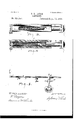
- Fig.3 is a side view of my device for keeping the apron taut; and
- Fig.4 is a longitudinal vertical section of the same.
- Fig.5 is aplan or top view showing the rear board attached to the rear girt, the seat attached to the wheel girt and a section of the divider girt.
- A represents the divider girt; A and E, portions of the divider; B, the rear girt of the platform; B, the forward girt or finger bar; 0, the canvasor belt carrier commonly called the lower apron or horizontal apron, D, the rear board; F, the grain wheel; G, the apron guides; H, a rear portion of the Wheel girt extended back for a support to the seat, and I the seat for the driver or operator of the harvester.
- this barrel of cast metal of the form shown, both ends being alike and the hole passing clear through it, so that the front and rear barrels are interchangeable.
- These sleeve or barrel sections of the apron guides butt against the ends of the wooden part, G, so as to close and retain the spring, g, therein.
- This spring pressing against the end of the stem or piston part of the sliding box, f, crowds or tends to crowd the latter out of the sleeve.
- This stop also serves to bound the movement of the sliding box and keeps it within the effective working range of its spring.
- These sleeves may form an integral part of the apron guides. As shown they are sections or continuations of the guides, and, together with the sliding box that bears the roll gudgeons, lie wholly Within the folds of the apron that shields and effectually protects them all from entanglement with the grain.
- the roll 0 may be either the drive or driven roll of the apron or belt. It is better ordinarily that it should be the idler or driven one. It is evident that it may be an elevator roll.
- the rear board D as heretofore shown in Letters Patent No. 422,601, granted me on the 4th day of March, 1890, has had the cleats Z and the hinge brackets is.
- the cleats serve not only to stiflen the board but as a means of attachment to the brackets to which they are secured by pivot bolts as shown.
- This rear board is swung on these pivot bolts and is secured in a horizontal, inclined or vertical position, with reference to the platform, by tightening up the nuts of the bolts.
- I extend the hinge bracket nearest thereto back so as to form a foot rest or step
- This form of the hinge bracket, provided with the stop and step, is very serviceable as an aid to the driver when, on a side hill, he desires to prevent the machine from overbalancing and the platform tipping up.
- the main wheel, or drive wheel is placed underneaththe elevator with the platform on one side and the binder on the other in such a position as to carry, for greater traction, most of the entire weight of the machine.
- the driver may prevent the platform from rising and the machine from tipping up or over by resting a foot and a part of, or his entire, weight upon the step, 70', if the rear board be up orin a vertical position, or by stepping directly upon the board if the latter be down or in a horizontal position.
- the rear board, D should be constructed to close up vertically and to be locked in that position, so in eifect forming a closed platform, when cutting short grain in a heavy wind; that it should be adjustable to any desired inclination and secured in that adj ustment to retard the tops of long grain that would otherwise run faster or in advance of the butter; that it should be constructed to open flat down orin a horizontal position to secure the full advantage of an open throatway for the passage of long grain and to support the tops of the grain in its passage; and that it should be stopped and positively held from passing beyond these working positions into unsafe and possibly fatal positions.
- hinge brackets, 7c have horizontal pivots on which the rear board freely turns in its adjustment, while they have vertical clamping plates centrally disposed around the pivots, and that pivot pins or other special pivots are avoided, the bolts that hold the board at any adjustment by clamping its cleats against the clamping plates, being themselves made the pivots on which the board turns in its adjustment.
- the apron guides having chambers, boxes for the roller bearings having plungers extending into the chambers and curved at their ends to conform with the roll to form guide surfaces for the edges of the belt Within the folds of which both guides and boxes lie, and springs within the chambers bearing against the boxes to carry them outto keep the belt taut.
- the apron guides having chambers and longitudinal slots into the chambers, sliding boxes carrying one of said rolls, moving in said chambers and curved at their ends to conform with the roll to form guide surfaces for the belt within the folds of which both guides and boxes lie, springs bearing against the boxes to carry them out to keep the belt taut, and stops working in said slots to limit the compression of the springs and hold the boxes in the chambers.
Landscapes
- Engineering & Computer Science (AREA)
- Mechanical Engineering (AREA)
- Spinning Or Twisting Of Yarns (AREA)
Description
(No Model.) 2 Sheets-Sheet 1.
S. D. LOGKE. HARVESTER. No. 525,957. Patented Sept. 11,1894.
WITNESSES INVENTEIR zam/a 94% (No Model.) S D LOCKE 2 Sheets-Sheet 2 HARVESTER. No. 525,957. Patented Sept. 11,1894.
WITNEEEEE= INVENTUR Nrrn STATES Fries.
ATEN'I HARVESTER.
- SPECIFICATION forming part of Letters Patent No. 52 5,957, dated September 11, 1894. Application filed March 23, 1885. Serial No. 159,873- (No model-l To all whom it may" concern:
Be it known that I, SYLVANUS D. LOOKE, of Hoosick Falls, in the county of Rensselaer, in the State of New York, have invented certain new and useful Improvements in Har 1\Jresters, of which the following is a specificalon.
My invention relates in part to the construction and arrangement of the apron guides and sliding boxes for the movable apron roll, relatively to the apron itself.
My .invention in some of its features is applicable to all harvesters.
To enable others skilled in the art to make and use my-invention, I will proceed to describe its construction and operation.
Figure 1 is a grain end elevation, ora view from the grain side, of the above mentioned harvester. The divider is partly cut away. Fig. 2 is a plan or top view of the same with the divider entirely removed and all'the harvester cut away except a section of the platform next to the grain wheel. Fig.3 isa side view of my device for keeping the apron taut; and Fig.4 is a longitudinal vertical section of the same. Fig.5 is aplan or top view showing the rear board attached to the rear girt, the seat attached to the wheel girt and a section of the divider girt.
In the drawings, A represents the divider girt; A and E, portions of the divider; B, the rear girt of the platform; B, the forward girt or finger bar; 0, the canvasor belt carrier commonly called the lower apron or horizontal apron, D, the rear board; F, the grain wheel; G, the apron guides; H, a rear portion of the Wheel girt extended back for a support to the seat, and I the seat for the driver or operator of the harvester.
In all harvesters using the common canvas apron or belt carrier a very serious and annoying difficulty is constantly met in the inability to keep the aprons or belts uniformly taut. This difficulty is due to the shrinking and expansion of the aprons by change of temperature or degree of moisture and results in much loss of time and great wear of the aprons. 'I avoid the difficulty by mounting the roll G of the apron C with its gudgeons, taking bearing in the cylindrical ends, f of the sliding boxes, f. Each of these boxes has lts stem or piston end sliding freely and longitudinally in a sleeve support or barrel, 6, that terminates and forms part of the apron guide G. I prefer to make this barrel of cast metal of the form shown, both ends being alike and the hole passing clear through it, so that the front and rear barrels are interchangeable. These sleeve or barrel sections of the apron guides butt against the ends of the wooden part, G, so as to close and retain the spring, g, therein. This spring, pressing against the end of the stem or piston part of the sliding box, f, crowds or tends to crowd the latter out of the sleeve.
A stop or set screw, h, on the piston end of the box, playing in a slot in the sleeve, prevents the box from being entirely crowded on t. This stop also serves to bound the movement of the sliding box and keeps it within the effective working range of its spring. These sleeves may form an integral part of the apron guides. As shown they are sections or continuations of the guides, and, together with the sliding box that bears the roll gudgeons, lie wholly Within the folds of the apron that shields and effectually protects them all from entanglement with the grain. The roll 0 may be either the drive or driven roll of the apron or belt. It is better ordinarily that it should be the idler or driven one. It is evident that it may be an elevator roll.
The rear board D, as heretofore shown in Letters Patent No. 422,601, granted me on the 4th day of March, 1890, has had the cleats Z and the hinge brackets is. The cleats serve not only to stiflen the board but as a means of attachment to the brackets to which they are secured by pivot bolts as shown. This rear board is swung on these pivot bolts and is secured in a horizontal, inclined or vertical position, with reference to the platform, by tightening up the nuts of the bolts. It is found, however, that when adjusted and the harvester is in operation, the rear board is liable to accidental displacement, and, if it falls back upon the ground oris adjusted too low it is liable to be broken when the harvester is backed, as in turning around at the corners. To prevent this result and provide a limit to the adjustment of the board, Icast a stop on the hinge bracket, one form of which stop is shown by k in Fig. 5, against which the cleat Z strikes and on which it rests IOC when the board D reaches, or nearly reaches, a horizontal position or adjustment.
To aid the driver in mounting the seat, I, I extend the hinge bracket nearest thereto back so as to form a foot rest or step, This form of the hinge bracket, provided with the stop and step, is very serviceable as an aid to the driver when, on a side hill, he desires to prevent the machine from overbalancing and the platform tipping up. In machines of this character the main wheel, or drive wheel, is placed underneaththe elevator with the platform on one side and the binder on the other in such a position as to carry, for greater traction, most of the entire weight of the machine. In my machine it is so placed and is located immediately to the right of the wheel girt, H, and between the rear girt B and the finger bar B, the wheel girt being extended back in the rear of the machine to serve as a seat girt or as a support for the seat standard I.
When the drive wheel is on the lower side of a steep side-hill the driver may prevent the platform from rising and the machine from tipping up or over by resting a foot and a part of, or his entire, weight upon the step, 70', if the rear board be up orin a vertical position, or by stepping directly upon the board if the latter be down or in a horizontal position.
To one skilled in the art, it is known that grain and particularly grass in the grain, is liable to enter between the folds of the canvas carrier or apron and end by winding tightly around the carrying rolls or their gudgeons, so enlarging the rolls a portion of their length and unduly stretching the apron out of proper shape or stopping it entirely. By placing the apron guides, into the ends of which the gudgeons of the apron rolls are journaled, wholly within the folds of the apron and widening them to say one and onehalf inches, reducing the length of the roller accordingly, this difficulty is greatly lessened or overcome. In practice, I have found it best not to make these guides so large as to crowd against the apron but to make them at their ends a very little smaller than the carrying rolls lest the edges of the apron, by rubbing hard upon the guides, be unnecessarily worn. The outer ends of the boxes, f, are rounded to conform to, but a little less than the face of the rolls, and so form the completion of the guides throughout substantially the whole extent of the apron.
To one skilled in the art, it is also apparent the rear board, D, should be constructed to close up vertically and to be locked in that position, so in eifect forming a closed platform, when cutting short grain in a heavy wind; that it should be adjustable to any desired inclination and secured in that adj ustment to retard the tops of long grain that would otherwise run faster or in advance of the butter; that it should be constructed to open flat down orin a horizontal position to secure the full advantage of an open throatway for the passage of long grain and to support the tops of the grain in its passage; and that it should be stopped and positively held from passing beyond these working positions into unsafe and possibly fatal positions. N ot unfrequently, the operator in manipulating or tightening the canvas or removing the gra n therefrom, accidentally rests a portion of h s weight on the board, thereby displacing it from its safe position and requiring its replacement at some expenditure of time. I prefer to make my rear board safe and secure and therefore provide the hinge bracket casting, 70, with a stop, 70 that bounds the movements of the board and on which it rests in its horizontal adjustment. These parts are made sufficiently strong and rigid to enable the operator, if occasion requires, to step d1- rectly and confidently upon the board.
It will be seen that the hinge brackets, 7c, have horizontal pivots on which the rear board freely turns in its adjustment, while they have vertical clamping plates centrally disposed around the pivots, and that pivot pins or other special pivots are avoided, the bolts that hold the board at any adjustment by clamping its cleats against the clamping plates, being themselves made the pivots on which the board turns in its adjustment.
I do not herein make any claim to the mechanism for adjustment of the grain wheel, having made that the subject-matter of an application filed by me on the 23d day of December, 1885, Serial No. 186,507, but
WhatI do claim herein,'and desire to secure by Letters Patent, is:-
1. The combination substantially as hereinbefore set forth, of the apron or carrier belt and the rolls therefor, the apron guides having chambers, boxes for the roller bearings having plungers extending into the chambers and curved at their ends to conform with the roll to form guide surfaces for the edges of the belt Within the folds of which both guides and boxes lie, and springs within the chambers bearing against the boxes to carry them outto keep the belt taut.
2. The combination substantially as hereinbefore set forth, of the apron or carrier belt and the rolls therefor, the apron guides having chambers and longitudinal slots into the chambers, sliding boxes carrying one of said rolls, moving in said chambers and curved at their ends to conform with the roll to form guide surfaces for the belt within the folds of which both guides and boxes lie, springs bearing against the boxes to carry them out to keep the belt taut, and stops working in said slots to limit the compression of the springs and hold the boxes in the chambers.
In witness whereof I have hereunto set my hand this 11th day of March, A. D. 1895.
SYLVANUS D. LOCKE.
Witnesses:
N. W. LOCKE, ADDISON GETTY.
ICC
Publications (1)
| Publication Number | Publication Date |
|---|---|
| US525957A true US525957A (en) | 1894-09-11 |
Family
ID=2594747
Family Applications (1)
| Application Number | Title | Priority Date | Filing Date |
|---|---|---|---|
| US525957D Expired - Lifetime US525957A (en) | Harvester |
Country Status (1)
| Country | Link |
|---|---|
| US (1) | US525957A (en) |
-
0
- US US525957D patent/US525957A/en not_active Expired - Lifetime
Similar Documents
| Publication | Publication Date | Title |
|---|---|---|
| US20140041354A1 (en) | Draper Header With Pivoting Side Draper Conveyors | |
| US525957A (en) | Harvester | |
| JP7116533B2 (en) | combine | |
| US591606A (en) | Endless-chain cutter | |
| US677127A (en) | Grinding-machine. | |
| US121005A (en) | Improvement in harvesters | |
| US1270285A (en) | Band-saw mill. | |
| US473300A (en) | Harvester | |
| US540313A (en) | Conveyer for grain-binders | |
| US107126A (en) | Improvement in binding attachment for harvesters | |
| US174755A (en) | Improvement in harvesters | |
| US611776A (en) | dennis | |
| US1240028A (en) | Grain harvester and binder. | |
| US2358548A (en) | Thresher | |
| US1188725A (en) | Manure-spreader. | |
| US658080A (en) | Belt-tightener for grain-carriers. | |
| US78710A (en) | of cobby | |
| US435522A (en) | Henry e | |
| US64523A (en) | Improvement in harvester-reels | |
| US770292A (en) | Harvester-elevator. | |
| US742489A (en) | Grain-divider. | |
| US609166A (en) | Charles e | |
| US1197808A (en) | Harvester-adjusting mechanism. | |
| US1000550A (en) | Attachment for harvesters. | |
| US1212427A (en) | Mowing-machine. |