US5259446A - Pressure pulse cleaning for adsorption tower distributors - Google Patents
Pressure pulse cleaning for adsorption tower distributors Download PDFInfo
- Publication number
- US5259446A US5259446A US07/809,377 US80937791A US5259446A US 5259446 A US5259446 A US 5259446A US 80937791 A US80937791 A US 80937791A US 5259446 A US5259446 A US 5259446A
- Authority
- US
- United States
- Prior art keywords
- distributor
- valve
- recited
- fluid
- accumulator
- Prior art date
- Legal status (The legal status is an assumption and is not a legal conclusion. Google has not performed a legal analysis and makes no representation as to the accuracy of the status listed.)
- Expired - Lifetime
Links
Images


Classifications
-
- C—CHEMISTRY; METALLURGY
- C01—INORGANIC CHEMISTRY
- C01B—NON-METALLIC ELEMENTS; COMPOUNDS THEREOF; METALLOIDS OR COMPOUNDS THEREOF NOT COVERED BY SUBCLASS C01C
- C01B5/00—Water
- C01B5/02—Heavy water; Preparation by chemical reaction of hydrogen isotopes or their compounds, e.g. 4ND3 + 7O2 ---> 4NO2 + 6D2O, 2D2 + O2 ---> 2D2O
-
- B—PERFORMING OPERATIONS; TRANSPORTING
- B08—CLEANING
- B08B—CLEANING IN GENERAL; PREVENTION OF FOULING IN GENERAL
- B08B3/00—Cleaning by methods involving the use or presence of liquid or steam
- B08B3/02—Cleaning by the force of jets or sprays
-
- B—PERFORMING OPERATIONS; TRANSPORTING
- B08—CLEANING
- B08B—CLEANING IN GENERAL; PREVENTION OF FOULING IN GENERAL
- B08B7/00—Cleaning by methods not provided for in a single other subclass or a single group in this subclass
-
- B—PERFORMING OPERATIONS; TRANSPORTING
- B08—CLEANING
- B08B—CLEANING IN GENERAL; PREVENTION OF FOULING IN GENERAL
- B08B2230/00—Other cleaning aspects applicable to all B08B range
- B08B2230/01—Cleaning with steam
Definitions
- the present invention relates in general to cleaning an adsorption tower, and more particularly to pressure pulse cleaning an adsorption tower to dislodge deposits from the distributors.
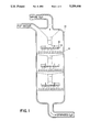
- FIG. 1 is a schematic diagram of a sectional view of such an adsorption tower.
- the tower (10) contains a plurality of distributors (12) oriented in a vertical arrangement.
- Each distributor (12) is essentially a large sprinkler with as many as four hundred 1/16 inch holes or openings (14) located on the bottom of tubes (16) extending out of the distributor (12), as best seen in FIG. 2.
- the heavy water descends through the tower (10) passing through each distributor (12) via the openings (14).
- a packing or heating coil (15) is ordinarily positioned under the distributor for filtering or heating in a known manner. Normally a liquid vapor such as H 2 O vapor in the example also enters the tower (10).
- shut downs may occur twice a year for a duration of six to eight weeks for cleaning the distributors.
- the shut downs are costly and cause radiation exposure to the workers as well as the environment.
- U.S. Pat. No. 5,006,304 discloses a method for loosening and removing sludge and debris from a nuclear steam generator by submerging a lower portion in water and then generating a succession of shock waves in the water by means of pulses of a pressurized gas. The disclosed method requires the operation to be shut down during cleaning.
- Related patents disclosing similar subject matter include U.S. Pat. No. 5,019,329, U.S. Pat. No. 4,899,697 and U.S. Pat. No. 4,921,662.
- U.S. Pat. No. 4,773,357 describes a method of cleaning the tube sheet of a heat exchanger by utilizing a water cannon for explosively discharging a quantity of water from the muzzle to dislodge sludge from the tube sheet of the heat exchanger.
- U.S. Pat. No. 4,905,900 describes a similar method.
- the present invention solves the aforementioned problems with the prior art as well as others by providing a method and apparatus for on-line cleaning of an adsorption tower having a plurality of distributors positioned therein.
- a regulated supply of a high pressure fluid is employed to generate a pressure pulse into the distributor for dislodging deposits blocking the openings therein.
- an accumulator is filled with the fluid to a predetermined pressure, and then the fluid is released into the distributor through a pressure conduit to cause the surge.
- the surge in pressure dislodges the deposits blocking the openings of the distributor.
- the distributors may either be cleaned singly in a sequential manner or simultaneously.
- An object of the present invention is to provide an on-line cleaning method and apparatus for dislodging deposits in the distributors of an adsorption tower.
- Another object of the present invention is to provide a method and apparatus for a sequential on-line cleaning of the distributors in an adsorption tower.
- a further object of the present invention is to provide such a device that is simple in design, rugged in construction, and economical to manufacture.
- FIG. 1 is a sectional schematic representation of an adsorption tower used in upgrading D 2 O for a nuclear power plant
- FIG. 2 is an elevational perspective view of the distributor
- FIG. 3 is a sectional schematic representation of an embodiment of the present invention.
- FIG. 4 is a sectional schematic representation of an alternate embodiment of the present invention.
- FIG. 5 is a sectional schematic representation of still another embodiment of the present invention attached to a single distributor.
- FIG. 1 depicts only one application for an adsorption tower which is the upgrading of heavy water.
- the distributors (12) are devices similar to a large sprinkler having a plurality of holes or openings (14) situated on the bottom of tubes (16) which extend on both sides of the distributor as shown in FIG. 2. Deposits are carried by the liquid entering the distributor (12) in the direction of the arrow causing a blockage of the openings (14) and the tube (16) of the distributor (12). The flow of the liquid through openings (14) are shown in dashed lines.
- FIG. 3 there is shown one embodiment of the present invention attached to the distributors (12) of the adsorption tower (10).
- a regulated supply of a high pressure fluid (18) such as nitrogen fills an accumulator (20) to a predetermined pressure.
- Valve switch (24) actuates a high speed valve (22) either manually or automatically to cause a surge of nitrogen through a common manifold (28) into the pressure conduits or lines (26) into the distributors (12).
- the nitrogen rapidly expands in the liquid in the distributors (12) which causes a pressure rise for dislodging any deposits blocking the openings (14).
- FIG. 3 shows a common manifold (28) with only one valve (22), it is apparent that each distributor can have its own valve (22) for a more selective control with the use of a computer or microprocessor (not shown). This allows the distributors to be cleaned invididually when necessary, sequentially, or simultaneously on-line without disrupting the process underway in the tower.
- An alternate embodiment includes the distributors (12) being connected individually to a single flexible line (28') as shown in FIG. 4.
- the valve switch (24) controls valve (22) either manually or automatically with the assistance of an optional computer.
- quick connect couplers (34) are employed and positioned outside the adsorption tower (10) to provide a means for quick connection to each distributor (12). After all of the distributors are cleaned, the device may be moved on to the next adsorption tower or away from the surrounding area.
- a single device may be used to quickly clean several towers with little exposure to the hostile environment.
- Quick connect couplers (34) are readily available for high pressure fluids. Those employed for compressed air are suitable for the present invention. Either of the embodiments shown in FIGS. 3 and 4 can use these quick connect couplers.
- the pressure conduits (26) may be fastened to the distributors in any of several different manners to provide a pressure tight seal.
- FIG. 5 depicts still another embodiment of the present invention which utilizes the injection of a liquid at high velocity into the distributor (12).
- An external force indicated by the arrow may be used either manually or automatically to drive a piston (30) of a pump (32) having a cavity of a predetermined volume and connected to a supply of fluid for injecting the liquid through the pressure conduit (26) into the distributor (12) at a very fast rate. This causes a pressure rise throughout the distributor of sufficient magnitude to clear the blocked openings.
- Either of the emobdiments in FIGS. 3 or 4 may be modified to use the injection of a liquid as shown in FIG. 5 rather than a gas.
- a further embodiment of the present invention utilizes ultrasonic transducers positioned in each of the distributors.
- the ultrasonic transducers are then actuated by a microprocessor or computer periodically to keep the holes clear.
Landscapes
- Chemical & Material Sciences (AREA)
- Organic Chemistry (AREA)
- Chemical Kinetics & Catalysis (AREA)
- Inorganic Chemistry (AREA)
- Separation Of Gases By Adsorption (AREA)
- Cleaning In General (AREA)
- Feeding, Discharge, Calcimining, Fusing, And Gas-Generation Devices (AREA)
Abstract
Description
Claims (13)
Priority Applications (3)
| Application Number | Priority Date | Filing Date | Title |
|---|---|---|---|
| US07/809,377 US5259446A (en) | 1991-12-18 | 1991-12-18 | Pressure pulse cleaning for adsorption tower distributors |
| US07/940,087 US5273590A (en) | 1991-12-18 | 1992-09-03 | Pressure pulse cleaning for adsorption tower distributors |
| CA002085569A CA2085569C (en) | 1991-12-18 | 1992-12-16 | Pressure pulse cleaning for adsorption tower distributors |
Applications Claiming Priority (1)
| Application Number | Priority Date | Filing Date | Title |
|---|---|---|---|
| US07/809,377 US5259446A (en) | 1991-12-18 | 1991-12-18 | Pressure pulse cleaning for adsorption tower distributors |
Related Child Applications (1)
| Application Number | Title | Priority Date | Filing Date |
|---|---|---|---|
| US07/940,087 Division US5273590A (en) | 1991-12-18 | 1992-09-03 | Pressure pulse cleaning for adsorption tower distributors |
Publications (1)
| Publication Number | Publication Date |
|---|---|
| US5259446A true US5259446A (en) | 1993-11-09 |
Family
ID=25201202
Family Applications (1)
| Application Number | Title | Priority Date | Filing Date |
|---|---|---|---|
| US07/809,377 Expired - Lifetime US5259446A (en) | 1991-12-18 | 1991-12-18 | Pressure pulse cleaning for adsorption tower distributors |
Country Status (2)
| Country | Link |
|---|---|
| US (1) | US5259446A (en) |
| CA (1) | CA2085569C (en) |
Cited By (3)
| Publication number | Priority date | Publication date | Assignee | Title |
|---|---|---|---|---|
| US5429077A (en) * | 1994-07-15 | 1995-07-04 | The Babcock & Wilcox Company | Water hammer rapper method and apparatus |
| US20140238643A1 (en) * | 2013-02-22 | 2014-08-28 | General Electric Company | System and method for cleaning heat exchangers |
| CN107537835A (en) * | 2017-10-19 | 2018-01-05 | 江西福事特液压有限公司 | Piston type washing steel pipes device |
Citations (4)
| Publication number | Priority date | Publication date | Assignee | Title |
|---|---|---|---|---|
| US3807960A (en) * | 1969-08-04 | 1974-04-30 | V Thayer | Apparatus for enrichment of deuterium between water and hydrogen sulfide by countercurrent mass transfer |
| US3894364A (en) * | 1972-12-04 | 1975-07-15 | Siemens Ag | Method of cleaning nuclear power plants |
| US3981977A (en) * | 1968-10-12 | 1976-09-21 | Rheinisch-Westfalisches-Elektrizitatswert Aktiengesellschaft | Method of producing deuterium-oxide-enriched water |
| US4562885A (en) * | 1983-08-29 | 1986-01-07 | General Resource Corporation | Plate heat exchanger and pressure blast cleaner |
-
1991
- 1991-12-18 US US07/809,377 patent/US5259446A/en not_active Expired - Lifetime
-
1992
- 1992-12-16 CA CA002085569A patent/CA2085569C/en not_active Expired - Lifetime
Patent Citations (4)
| Publication number | Priority date | Publication date | Assignee | Title |
|---|---|---|---|---|
| US3981977A (en) * | 1968-10-12 | 1976-09-21 | Rheinisch-Westfalisches-Elektrizitatswert Aktiengesellschaft | Method of producing deuterium-oxide-enriched water |
| US3807960A (en) * | 1969-08-04 | 1974-04-30 | V Thayer | Apparatus for enrichment of deuterium between water and hydrogen sulfide by countercurrent mass transfer |
| US3894364A (en) * | 1972-12-04 | 1975-07-15 | Siemens Ag | Method of cleaning nuclear power plants |
| US4562885A (en) * | 1983-08-29 | 1986-01-07 | General Resource Corporation | Plate heat exchanger and pressure blast cleaner |
Cited By (3)
| Publication number | Priority date | Publication date | Assignee | Title |
|---|---|---|---|---|
| US5429077A (en) * | 1994-07-15 | 1995-07-04 | The Babcock & Wilcox Company | Water hammer rapper method and apparatus |
| US20140238643A1 (en) * | 2013-02-22 | 2014-08-28 | General Electric Company | System and method for cleaning heat exchangers |
| CN107537835A (en) * | 2017-10-19 | 2018-01-05 | 江西福事特液压有限公司 | Piston type washing steel pipes device |
Also Published As
| Publication number | Publication date |
|---|---|
| CA2085569A1 (en) | 1993-06-19 |
| CA2085569C (en) | 2000-05-09 |
Similar Documents
| Publication | Publication Date | Title |
|---|---|---|
| US4566406A (en) | Sludge removing apparatus for a steam generator | |
| US6572709B1 (en) | Ultrasonic cleaning method | |
| KR860001448A (en) | Method and apparatus for removing residual sludge from nuclear steam generator | |
| US4699665A (en) | Method of pressure pulse cleaning heat exchanger tubes, upper tube support plates and other areas in a nuclear steam generator and other tube bundle heat exchangers | |
| US5078760A (en) | Separation of particulate from gases produced by combustion of fossil material | |
| CA2378932C (en) | An ultrasonic cleaning method | |
| RU2436026C2 (en) | Method and device for cleaning water-sprinkled surfaces of air-to-water heat exchanger | |
| JPS6051001B2 (en) | Steam generator sludge removal method | |
| US4498427A (en) | Sludge lance with multiple nozzle jet head | |
| MXPA03006050A (en) | Prevention of unwanted material accumulations. | |
| CA2091357A1 (en) | Method and apparatus for converting pressurized low continuous flow to high flow in pulses | |
| EP0440465A1 (en) | Method and apparatus for removing foreign matter from heat exchanger tubesheets | |
| EP0147577B1 (en) | Multiple jet backflushed air filter | |
| JPH0217390A (en) | Method of separating and removing sludge and foreign matter from inside of heat exchanger | |
| US5259446A (en) | Pressure pulse cleaning for adsorption tower distributors | |
| US5273590A (en) | Pressure pulse cleaning for adsorption tower distributors | |
| US4848278A (en) | Nuclear steam generator sludge lancing method and apparatus | |
| DE2725045A1 (en) | Engine exhaust gas heat exchanger cleaning system - injects water at intervals into heat exchanger while engine is working | |
| KR20030079954A (en) | A method and apparatus for radioactive decontamination of a surface situated inside a hollow body | |
| CA1237349A (en) | Sludge removal device for cleaning the tubular plate of a steam generator | |
| US4556486A (en) | Circulating water filtering system and method of operation | |
| US5301424A (en) | Method for hydraulically expanding tubular members | |
| US4601885A (en) | Sterilization system | |
| US4529516A (en) | Self-flushing magnetic separtor | |
| JP3831876B2 (en) | Apparatus and method for cleaning filter elements |
Legal Events
| Date | Code | Title | Description |
|---|---|---|---|
| AS | Assignment |
Owner name: BABCOCK & WILCOX COMPANY, THE A CORPORATION OF Free format text: ASSIGNMENT OF ASSIGNORS INTEREST.;ASSIGNOR:ST. LOUIS, DANIEL M.;REEL/FRAME:005967/0237 Effective date: 19911217 Owner name: BABCOCK & WILCOX COMPANY, THE, LOUISIANA Free format text: ASSIGNMENT OF ASSIGNORS INTEREST;ASSIGNOR:ST. LOUIS, DANIEL M.;REEL/FRAME:005967/0237 Effective date: 19911217 |
|
| STCF | Information on status: patent grant |
Free format text: PATENTED CASE |
|
| FEPP | Fee payment procedure |
Free format text: PAYOR NUMBER ASSIGNED (ORIGINAL EVENT CODE: ASPN); ENTITY STATUS OF PATENT OWNER: LARGE ENTITY |
|
| FPAY | Fee payment |
Year of fee payment: 4 |
|
| FPAY | Fee payment |
Year of fee payment: 8 |
|
| FPAY | Fee payment |
Year of fee payment: 12 |
|
| AS | Assignment |
Owner name: CREDIT SUISSE, CAYMAN ISLANDS BRANCH, AS COLLATERA Free format text: SECURITY AGREEMENT;ASSIGNOR:THE BABCOCK & WILCOX COMPANY;REEL/FRAME:017344/0565 Effective date: 20060222 |
|
| AS | Assignment |
Owner name: THE BABCOCK & WILCOX POWER GENERATION GROUP, INC., Free format text: CHANGE OF NAME;ASSIGNOR:THE BABCOCK & WILCOX COMPANY;REEL/FRAME:021998/0870 Effective date: 20071120 |
|
| AS | Assignment |
Owner name: POWER SYSTEMS OPERATIONS, INC., OHIO Free format text: RELEASE BY SECURED PARTY;ASSIGNOR:CREDIT SUISSE AG, CAYMAN ISLANDS BRANCH;REEL/FRAME:024776/0693 Effective date: 20100503 Owner name: BABCOCK & WILCOX CONSTRUCTION CO., INC., OHIO Free format text: RELEASE BY SECURED PARTY;ASSIGNOR:CREDIT SUISSE AG, CAYMAN ISLANDS BRANCH;REEL/FRAME:024776/0693 Effective date: 20100503 Owner name: PALM BEACH RESOURCE RECOVERY CORPORATION, FLORIDA Free format text: RELEASE BY SECURED PARTY;ASSIGNOR:CREDIT SUISSE AG, CAYMAN ISLANDS BRANCH;REEL/FRAME:024776/0693 Effective date: 20100503 Owner name: DIAMOND POWER CHINA HOLDINGS, INC., OHIO Free format text: RELEASE BY SECURED PARTY;ASSIGNOR:CREDIT SUISSE AG, CAYMAN ISLANDS BRANCH;REEL/FRAME:024776/0693 Effective date: 20100503 Owner name: BABCOCK & WILCOX CHINA HOLDINGS, INC., OHIO Free format text: RELEASE BY SECURED PARTY;ASSIGNOR:CREDIT SUISSE AG, CAYMAN ISLANDS BRANCH;REEL/FRAME:024776/0693 Effective date: 20100503 Owner name: BABCOCK & WILCOX EBENSBURG POWER, INC., OHIO Free format text: RELEASE BY SECURED PARTY;ASSIGNOR:CREDIT SUISSE AG, CAYMAN ISLANDS BRANCH;REEL/FRAME:024776/0693 Effective date: 20100503 Owner name: AMERICON EQUIPMENT SERVICES, INC., OHIO Free format text: RELEASE BY SECURED PARTY;ASSIGNOR:CREDIT SUISSE AG, CAYMAN ISLANDS BRANCH;REEL/FRAME:024776/0693 Effective date: 20100503 Owner name: BABCOCK & WILCOX DENMARK HOLDINGS, INC., OHIO Free format text: RELEASE BY SECURED PARTY;ASSIGNOR:CREDIT SUISSE AG, CAYMAN ISLANDS BRANCH;REEL/FRAME:024776/0693 Effective date: 20100503 Owner name: REVLOC RECLAMATION SERVICE, INC., OHIO Free format text: RELEASE BY SECURED PARTY;ASSIGNOR:CREDIT SUISSE AG, CAYMAN ISLANDS BRANCH;REEL/FRAME:024776/0693 Effective date: 20100503 Owner name: DIAMOND POWER EQUITY INVESTMENTS, INC., OHIO Free format text: RELEASE BY SECURED PARTY;ASSIGNOR:CREDIT SUISSE AG, CAYMAN ISLANDS BRANCH;REEL/FRAME:024776/0693 Effective date: 20100503 Owner name: BABCOCK & WILCOX EQUITY INVESTMENTS, INC., OHIO Free format text: RELEASE BY SECURED PARTY;ASSIGNOR:CREDIT SUISSE AG, CAYMAN ISLANDS BRANCH;REEL/FRAME:024776/0693 Effective date: 20100503 Owner name: DIAMOND OPERATING CO., INC., PENNSYLVANIA Free format text: RELEASE BY SECURED PARTY;ASSIGNOR:CREDIT SUISSE AG, CAYMAN ISLANDS BRANCH;REEL/FRAME:024776/0693 Effective date: 20100503 Owner name: AMERICON, INC., OHIO Free format text: RELEASE BY SECURED PARTY;ASSIGNOR:CREDIT SUISSE AG, CAYMAN ISLANDS BRANCH;REEL/FRAME:024776/0693 Effective date: 20100503 Owner name: THE BABCOCK & WILCOX COMPANY, NORTH CAROLINA Free format text: RELEASE BY SECURED PARTY;ASSIGNOR:CREDIT SUISSE AG, CAYMAN ISLANDS BRANCH;REEL/FRAME:024776/0693 Effective date: 20100503 Owner name: NORTH COUNTY RECYCLING, INC., NORTH CAROLINA Free format text: RELEASE BY SECURED PARTY;ASSIGNOR:CREDIT SUISSE AG, CAYMAN ISLANDS BRANCH;REEL/FRAME:024776/0693 Effective date: 20100503 Owner name: APPLIED SYNERGISTICS, INC., VIRGINIA Free format text: RELEASE BY SECURED PARTY;ASSIGNOR:CREDIT SUISSE AG, CAYMAN ISLANDS BRANCH;REEL/FRAME:024776/0693 Effective date: 20100503 Owner name: B & W SERVICE COMPANY, NORTH CAROLINA Free format text: RELEASE BY SECURED PARTY;ASSIGNOR:CREDIT SUISSE AG, CAYMAN ISLANDS BRANCH;REEL/FRAME:024776/0693 Effective date: 20100503 Owner name: NATIONAL ECOLOGY COMPANY, OHIO Free format text: RELEASE BY SECURED PARTY;ASSIGNOR:CREDIT SUISSE AG, CAYMAN ISLANDS BRANCH;REEL/FRAME:024776/0693 Effective date: 20100503 Owner name: DIAMOND POWER AUSTRALIA HOLDINGS, INC., OHIO Free format text: RELEASE BY SECURED PARTY;ASSIGNOR:CREDIT SUISSE AG, CAYMAN ISLANDS BRANCH;REEL/FRAME:024776/0693 Effective date: 20100503 Owner name: BABCOCK & WILCOX INTERNATIONAL SALES AND SERVICE C Free format text: RELEASE BY SECURED PARTY;ASSIGNOR:CREDIT SUISSE AG, CAYMAN ISLANDS BRANCH;REEL/FRAME:024776/0693 Effective date: 20100503 Owner name: DIAMOND POWER INTERNATIONAL, INC., OHIO Free format text: RELEASE BY SECURED PARTY;ASSIGNOR:CREDIT SUISSE AG, CAYMAN ISLANDS BRANCH;REEL/FRAME:024776/0693 Effective date: 20100503 Owner name: BABCOCK & WILCOX INTERNATIONAL, INC., OHIO Free format text: RELEASE BY SECURED PARTY;ASSIGNOR:CREDIT SUISSE AG, CAYMAN ISLANDS BRANCH;REEL/FRAME:024776/0693 Effective date: 20100503 |