US525927A - Metallic railway-tie - Google Patents
Metallic railway-tie Download PDFInfo
- Publication number
- US525927A US525927A US525927DA US525927A US 525927 A US525927 A US 525927A US 525927D A US525927D A US 525927DA US 525927 A US525927 A US 525927A
- Authority
- US
- United States
- Prior art keywords
- tie
- rails
- sleepers
- limbs
- stretchers
- Prior art date
- Legal status (The legal status is an assumption and is not a legal conclusion. Google has not performed a legal analysis and makes no representation as to the accuracy of the status listed.)
- Expired - Lifetime
Links
- 210000003414 extremity Anatomy 0.000 description 11
- 241001669679 Eleotris Species 0.000 description 7
- 210000003141 lower extremity Anatomy 0.000 description 4
- 235000000396 iron Nutrition 0.000 description 2
- 230000008602 contraction Effects 0.000 description 1
- 238000006073 displacement reaction Methods 0.000 description 1
- 239000002184 metal Substances 0.000 description 1
- 230000002459 sustained effect Effects 0.000 description 1
Images

Classifications
-
- B—PERFORMING OPERATIONS; TRANSPORTING
- B61—RAILWAYS
- B61C—LOCOMOTIVES; MOTOR RAILCARS
- B61C13/00—Locomotives or motor railcars characterised by their application to special systems or purposes
- B61C13/04—Locomotives or motor railcars characterised by their application to special systems or purposes for elevated railways with rigid rails
Definitions
- My invention consists of a sleeper having an inverted T shaped slot therein, and provided with the cheek pieces extending upwardly and a tie of inverted T form having both of its limbs occupying said slot, the lower limb of said tie being locked in the lower limb of the slot, so that the tie is prevented from an upward movement in the event of wash-outs or other accident, when said tie is subjected to upwardstrain or pressure from below.
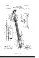
- Figures 1 and 4 represent perspective views of railway ties, embodying my invention.
- Fig. 2 represents a vertical section on line x, 00, Fig. 1.
- Fig. 3 represents a vertical section on line y, y, Fig. 2.
- Fig. 5 represents a vertical section on line 2', .2, Fig. at.
- Fig. 6 represents a vertical section on line a, a, Fig. 5.
- A designates a metallic tie and support for a railroad rail
- inverted channel plates or sleepers B on which the rails are placed, and the stretchers or connecting ties O which extend transversely from opposite end pieces, said stretchers being formed of inverted T- irons or bars which pass through similarlyshaped slots D in the vertical limbs or portions of the ties B.
- the upper faces of the sleepers B which form the supports or beds for the rails are provided with cheek pieces E, which are bent upwardly from the same, and the portions of the vertical limbs of the stretchers which are beneath the rails are cut away or recessed'as at F, the bottom wall of the recess being flush with the tops of the sleepers B, and serving to have the contiguous part of the base of the rail superimposed sides of the flanges of the rails, it being seen that the rails are supported on both the plates B and the stretchers O, and that said plates are braced and stifiened by said stretchers, whereby strong structures are provided, and the rails are firmly sustained and fastened, and. prevented from spreading, as the cheek pieces G are opposed to each other and resist such spreading or lateral strain, due to the outward strain of the rails againstsaid cheek pieces G, when the rails are occupied.
- Figs. 4., 5, and 6, I show two stretchers H, each of angle irons or bars passed through the sleepers B on opposite sides of thejoints J, H, of the rails, thus increasing the strength of the sleepers B, and sustaining the ends of adjacent rails on said sleepers.
- the sides of the inner limbs of the sleepers are cut away as at K, so as to taper said sides, and thus provide convenient means for tamping, it being noticed that the limbs of the sleepers flare downwardly so as to provide wide bases, and enlarge the spaces for ballasting.
- the sleepers and stretchers are made of wrought metal, and that the ties are elastic in their nature, avoiding deadness and rigidity in the support of the rails.
- the sleepersand stretchers may expand and contract without loosening the rails, as the latter will move with such expansion and contraction, thus preventing rattling or loosening of the rails, it being also noticed that keys, wedges, pins or other fastenings are dispensed with for connecting the stretchers and the ties, and vice-versa.
- a metallic sleeper of inverted channel 15 form having its limbs cutaway at the sides thereof, substantially as and for the purpose described.
Landscapes
- Engineering & Computer Science (AREA)
- Transportation (AREA)
- Mechanical Engineering (AREA)
- Machines For Laying And Maintaining Railways (AREA)
Description
(No Model.) 2 Sheets-Sheet l. E. L. TAYLOR.
METALLIC RAILWAY TIE. No. 525,927. Patented Sept. 11, 1894.
A TTOR/VE Y.
(No Model.) 2 Sheets-Shed; 2.
EL. TAYLOR,
UNITED STATES PATENT OFFICE.
EN OOH 'LEWIS TAYLOR, OFPHILADELPHIA, PENNSYLVANIA.
M ETALLIC RAlLWAY-Tl E.
SPECIFICATION forming part of Letters-Patent No. 525,927, dated September 11, 1894.
Application filed August 26, 1893. Serial. No. 484.108- (No modem To all whom it may concern: f
Be it known'that I, ENOCH LEWIS TAYLOR, a citizen of the United States, residing in the city and county of Philadelphia, State of Pennsylvania, have invented a new and useful Improvement in Metallic Railway-Ties, which improvement is fully set forth in the following specification and accompanying drawings.
My invention consists of a sleeper having an inverted T shaped slot therein, and provided with the cheek pieces extending upwardly and a tie of inverted T form having both of its limbs occupying said slot, the lower limb of said tie being locked in the lower limb of the slot, so that the tie is prevented from an upward movement in the event of wash-outs or other accident, when said tie is subjected to upwardstrain or pressure from below.
It also consists in so constructing the sides of the sleepers as to provide convenient means for tamping, as will be hereinafter set forth.
Figures 1 and 4 represent perspective views of railway ties, embodying my invention. Fig. 2 represents a vertical section on line x, 00, Fig. 1. Fig. 3 represents a vertical section on line y, y, Fig. 2. Fig. 5 represents a vertical section on line 2', .2, Fig. at. Fig. 6 represents a vertical section on line a, a, Fig. 5.
Similar letters of reference indicate corresponding parts in the several figures.
Referring to the drawings: A designates a metallic tie and support for a railroad rail,
the same consisting of inverted channel plates or sleepers B, on which the rails are placed, and the stretchers or connecting ties O which extend transversely from opposite end pieces, said stretchers being formed of inverted T- irons or bars which pass through similarlyshaped slots D in the vertical limbs or portions of the ties B. The upper faces of the sleepers B which form the supports or beds for the rails, are provided with cheek pieces E, which are bent upwardly from the same, and the portions of the vertical limbs of the stretchers which are beneath the rails are cut away or recessed'as at F, the bottom wall of the recess being flush with the tops of the sleepers B, and serving to have the contiguous part of the base of the rail superimposed sides of the flanges of the rails, it being seen that the rails are supported on both the plates B and the stretchers O, and that said plates are braced and stifiened by said stretchers, whereby strong structures are provided, and the rails are firmly sustained and fastened, and. prevented from spreading, as the cheek pieces G are opposed to each other and resist such spreading or lateral strain, due to the outward strain of the rails againstsaid cheek pieces G, when the rails are occupied.
In Figs. 4., 5, and 6, I show two stretchers H, each of angle irons or bars passed through the sleepers B on opposite sides of thejoints J, H, of the rails, thus increasing the strength of the sleepers B, and sustaining the ends of adjacent rails on said sleepers. The sides of the inner limbs of the sleepers are cut away as at K, so as to taper said sides, and thus provide convenient means for tamping, it being noticed that the limbs of the sleepers flare downwardly so as to provide wide bases, and enlarge the spaces for ballasting. It will also be seen that the sleepers and stretchers are made of wrought metal, and that the ties are elastic in their nature, avoiding deadness and rigidity in the support of the rails. Furthermore, the sleepersand stretchers may expand and contract without loosening the rails, as the latter will move with such expansion and contraction, thus preventing rattling or loosening of the rails, it being also noticed that keys, wedges, pins or other fastenings are dispensed with for connecting the stretchers and the ties, and vice-versa.
By having the stretcher or tie proper of angle or shape, and the lower limb or limbs thereof supported on the wall of the similarly shaped slots in the sleepers, the same is more firmly secured in place, and greater resistance to horizontal pressure thereon is afforded.
Having thus described my invention, what I claim as new, and desire tosecure by Letters Patent, is
1. The combination of a metallic sleeper 5 formed with an inverted T shaped slot,in its limbs, and provided with cheek pieces bent upwardly from the same and a tie of inverted T shaped. form having its limbs freely occupying said slot, the horizontal limbs of said to slot of said tie being below, whereby the tie is locked in the sleeper and prevented from upward displacement therefrom, substantially as described.
2. A metallic sleeper of inverted channel 15 form having its limbs cutaway at the sides thereof, substantially as and for the purpose described.
3. The combination with a tie of inverted T shape, of a metallic sleeper having an inverted T shapeslot which freely receives both verted T-shape, having a recess in its vertical limb, to receive the base of a rail, witha sleeper having depending limbs with an in- 1 verted T shaped slot in each of the same, to receive said tie, and cheek pieces on said sleeper to embrace one side of the base of the rail, the tie having a cheek piece to embrace the other side of the base of the rail, substantially as described.
ENOCH LEWIS TAYLOR. Witnesses:
J OHN A. WIEDE'RSHEIM, A. P. JENNINGS.
Publications (1)
| Publication Number | Publication Date |
|---|---|
| US525927A true US525927A (en) | 1894-09-11 |
Family
ID=2594717
Family Applications (1)
| Application Number | Title | Priority Date | Filing Date |
|---|---|---|---|
| US525927D Expired - Lifetime US525927A (en) | Metallic railway-tie |
Country Status (1)
| Country | Link |
|---|---|
| US (1) | US525927A (en) |
-
0
- US US525927D patent/US525927A/en not_active Expired - Lifetime
Similar Documents
| Publication | Publication Date | Title |
|---|---|---|
| RU184004U1 (en) | RAIL ANCHOR ANCHOR | |
| US317988A (en) | Thomas h | |
| US525927A (en) | Metallic railway-tie | |
| US1024065A (en) | Metal rail-tie. | |
| US333015A (en) | James howaed and edwaed tenney bousfield | |
| US469392A (en) | Street railway or tramway | |
| US744285A (en) | Metallic railway-tie. | |
| US524999A (en) | Railroad-tie | |
| US216846A (en) | Improvement in rail tie and joint | |
| US361330A (en) | Metallic cross tie and means for attaching the rails thereto | |
| US1143442A (en) | Railway-tie. | |
| US365511A (en) | geoeget | |
| US510391A (en) | Railroad-rail | |
| US1170351A (en) | Base-plate. | |
| US823828A (en) | Means for securing rails. | |
| US464054A (en) | Jacob c | |
| US923370A (en) | Metal railway-tie and rail-fastening means. | |
| US1177103A (en) | Metallic railroad-tie. | |
| US441926A (en) | Metallic cross-tie | |
| US706788A (en) | Metallic railway-tie. | |
| US320869A (en) | Construction of railway-tracks | |
| US505020A (en) | Railway-tie | |
| US765603A (en) | Metal railway-tie. | |
| US471582A (en) | Metallic railway-tie | |
| US342987A (en) | Railway-tie |