US5259185A - Fuel drainage connector system for aircraft gas turbine - Google Patents
Fuel drainage connector system for aircraft gas turbine Download PDFInfo
- Publication number
- US5259185A US5259185A US07/894,673 US89467392A US5259185A US 5259185 A US5259185 A US 5259185A US 89467392 A US89467392 A US 89467392A US 5259185 A US5259185 A US 5259185A
- Authority
- US
- United States
- Prior art keywords
- fuel
- drain
- flange
- fingers
- detachable
- Prior art date
- Legal status (The legal status is an assumption and is not a legal conclusion. Google has not performed a legal analysis and makes no representation as to the accuracy of the status listed.)
- Expired - Fee Related
Links
- 239000000446 fuel Substances 0.000 title claims abstract description 75
- 230000000452 restraining effect Effects 0.000 claims 1
- 238000002485 combustion reaction Methods 0.000 description 6
- 230000013011 mating Effects 0.000 description 3
- 230000000712 assembly Effects 0.000 description 2
- 238000000429 assembly Methods 0.000 description 2
- 238000010276 construction Methods 0.000 description 2
- 230000008878 coupling Effects 0.000 description 2
- 238000010168 coupling process Methods 0.000 description 2
- 238000005859 coupling reaction Methods 0.000 description 2
- 238000003763 carbonization Methods 0.000 description 1
- 238000009434 installation Methods 0.000 description 1
- 239000000463 material Substances 0.000 description 1
- 230000002265 prevention Effects 0.000 description 1
- 239000007921 spray Substances 0.000 description 1
Images


Classifications
-
- F—MECHANICAL ENGINEERING; LIGHTING; HEATING; WEAPONS; BLASTING
- F02—COMBUSTION ENGINES; HOT-GAS OR COMBUSTION-PRODUCT ENGINE PLANTS
- F02C—GAS-TURBINE PLANTS; AIR INTAKES FOR JET-PROPULSION PLANTS; CONTROLLING FUEL SUPPLY IN AIR-BREATHING JET-PROPULSION PLANTS
- F02C7/00—Features, components parts, details or accessories, not provided for in, or of interest apart form groups F02C1/00 - F02C6/00; Air intakes for jet-propulsion plants
- F02C7/22—Fuel supply systems
- F02C7/222—Fuel flow conduits, e.g. manifolds
-
- F—MECHANICAL ENGINEERING; LIGHTING; HEATING; WEAPONS; BLASTING
- F02—COMBUSTION ENGINES; HOT-GAS OR COMBUSTION-PRODUCT ENGINE PLANTS
- F02C—GAS-TURBINE PLANTS; AIR INTAKES FOR JET-PROPULSION PLANTS; CONTROLLING FUEL SUPPLY IN AIR-BREATHING JET-PROPULSION PLANTS
- F02C7/00—Features, components parts, details or accessories, not provided for in, or of interest apart form groups F02C1/00 - F02C6/00; Air intakes for jet-propulsion plants
- F02C7/22—Fuel supply systems
- F02C7/232—Fuel valves; Draining valves or systems
-
- F—MECHANICAL ENGINEERING; LIGHTING; HEATING; WEAPONS; BLASTING
- F05—INDEXING SCHEMES RELATING TO ENGINES OR PUMPS IN VARIOUS SUBCLASSES OF CLASSES F01-F04
- F05D—INDEXING SCHEME FOR ASPECTS RELATING TO NON-POSITIVE-DISPLACEMENT MACHINES OR ENGINES, GAS-TURBINES OR JET-PROPULSION PLANTS
- F05D2260/00—Function
- F05D2260/60—Fluid transfer
- F05D2260/602—Drainage
Definitions
- This invention relates to a detachable drain system for the multiple fuel segments which provide fuel to fuel nozzles projecting into an aircraft gas turbine combustion chamber.
- Unburnt fuel drainage is of vital importance when aircraft gas turbines are shut down, either after a period of operation or where the starting cycle is not completed because combustion did not begin.
- Combustion chamber drain arrangements are shown, for example, in U.S. Pat. No. 2,846,845, issued Aug. 12, 1958 and assigned to the same assignee as the present invention.
- a typical fuel drain manifold system may include multiple connectors which employ nuts with lockwires, requiring special tools to install and remove with such operations being relatively difficult and time consuming. It is important to prevent fuel in the fuel supply lines from leaking through the nozzles into the combustion chamber when the gas turbine is shut down because of the tendency for the fuel inlets to clog due to the carbonization of the fuel as it issues slowly from the heated nozzles.
- Another object of this invention is to provide an improved fuel drain manifold system which requires no special tools to install or detach.
- a further object of this invention is to provide an improved fuel drain manifold system which facilitates the proper positioning and securing of the manifold system on the aircraft gas turbine and prevention or containment of fuel leakage in the region of the turbine fire zone.
- the fuel manifold drain cans on an aircraft gas turbine include connector assemblies having a first connector with a pair of diametrically opposed and radially inwardly extending fingers which are integral with the drain shroud which are guided into mating slots in a second connector comprising a locking ring fastened to the fuel nozzle, whereupon the drain shroud is rotated to lock the connectors together.
- the locking ring In the locked position, the locking ring is surrounded by an annulus and a resilient washer within the annulus is compressed between a shoulder on the rotatable annulus and an axially facing surface on the locking ring providing a leak-proof seal.
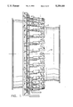
- FIG. 1 shows a fuel manifold system for an aircraft gas turbine incorporating the present invention.
- FIG. 2 is an enlarged portion of FIG. 1 showing details of the invention.
- FIG. 3 is a cross section of a portion of FIG. 2 taken in the direction of the arrows 3--3 in FIG. 2.
- FIG. 4 is a side view in cross section of a portion of FIG. 3 taken in the direction shown by the arrows 4--4 in FIG. 3.
- a fuel manifold 1 surrounding the combustor casing 2 includes a plurality of fuel manifold drain cans such as 4 positioned circumferentially around the combustor casing.
- fuel manifold drain can assemblies 4 may be utilized in connection with an equal number of fuel lines, each of which is associated with a fuel nozzle 6 extending through walls 8 of the combustor casing 2 toward the axis 10 of the combustor casing.
- Fuel nozzle 6 extends radially inward from the outer wall 8 of the combustor casing 2 to provide the desired fuel spray pattern within the combustor chamber.
- Fuel line 15 connects through the valve 21 positioned within drain chamber 23 formed within cylindrical drain can 5, and sealed on either side by O-rings 9.
- Drain hole 22 connects drain chamber 23 of drain can assembly 4 to drain sump 24 positioned below the drain can, as best shown in FIG. 3.
- the drain sump 24 is connected through drain return 26, connector 27 and drain line 28 to fuel drain manifold 29 to carry the drained fuel away from combustor casing 2.
- cylindrical drain can 5 includes a cylindrical terminal portion 39 having a diameter greater than that of the cylindrical drain can, connected by neck 38, and including diametrically opposed fingers 40 extending transverse to the cylindrical terminal portion and to axis 3, wherein fingers 40 include a radially inner surface 47 as best seen in FIG. 4.
- a flange 30 is secured to tubular pipe 16 which connects through support 18 to fuel nozzle 6.
- Flange 30 is positioned within terminal cylindrical portion 39 of drain can 5 when detachable coupling 36 is engaged and locked.
- Flange 30 includes a pair of opposed and substantially parallel axially facing surfaces 35 and 48, and a pair of diametrically opposed and axially extending stops 32 secured to axially facing surface 35.
- Flange 30 further includes a radially outer surface 49 having a diameter greater than that of radially inner surface 47 of fingers 40 and less than a diameter of a radially inner surface 50 of cylindrical terminal portion 39.
- flange 30 includes a pair of circumferentially extending slots or openings 31, wherein each of the slots 31 extend over an arc length which is greater than an arc length of each of fingers 40, thereby permitting cylindrical terminal portion 39 to be positioned over outer surface 49 of flange 30 by aligning fingers 40 of drain can 5 and slots 31 of flange 30.
- Axially extending stops 32 are positioned and sized such that, after passing fingers 40 through slots 31 and rotating drain can 5 in the counterclockwise direction as shown by arrow 46 in FIG. 4, each of the stops 32 contacts one of fingers 40.
- drain can 5 is rotatable through a limited angle between the stops 32 which are positioned approximately 180° apart and extend over approximately 40° of arc.
- Flange 13 of support 18 is secured to combustor casing 2 by three bolts 12.
- Spring washer 44 is positioned within an annular groove 42 within cylindrical portion 39 adjacent neck 38. Drain can 5 is detachably secured to tubular pipe 16 of fuel nozzle assembly 11 by inserting fingers 40 of drain can 5 through slots 31 of flange 30 and rotating drain can 5 between fingers 40, and rotating the flange in the counterclockwise direction, as shown by arrow 46 in FIG. 4 as noted previously. Rotation of flange 30 is accomplished against the pressure of spring washer 44 which contacts axially facing surface 49 of flange 30 thereby forcing axially facing surface 35 of flange 30 against fingers 40, helping to secure the drain can assembly 4 in position when rotational pressure is removed. However, the use of spring washer 44 is optional.
- Drain can assembly 4 thus contains, drains, and removes fuel from the fire zone of the engine including any fuel leakage from joints within the assembly.
- Drain can assembly 4 can be readily removed from tubular pipe 16 of fuel nozzle assembly 11 by rotation in a direction opposite to that shown by arrow 46, that is, clockwise in FIG. 4, until fingers 40 of drain can 5 are positioned within slots 31 of flange 30, after which drain can 5 can be slid axially away from rotatable flange 30 and tubular pipe 16 of fuel nozzle assembly 11. The drain can 5 may then be slid over O-ring seals 9, exposing the couplinq 51 of valve 21 of fuel nozzle assembly 11.
Landscapes
- Engineering & Computer Science (AREA)
- Chemical & Material Sciences (AREA)
- Combustion & Propulsion (AREA)
- Mechanical Engineering (AREA)
- General Engineering & Computer Science (AREA)
- Joints Allowing Movement (AREA)
Abstract
A fuel drain can assembly positioned between the fuel manifold and the fuel nozzles of a gas turbine engine which utilizes detachable connectors rotatable into locking engagement without special tooling.
Description
This invention relates to a detachable drain system for the multiple fuel segments which provide fuel to fuel nozzles projecting into an aircraft gas turbine combustion chamber.
Unburnt fuel drainage is of vital importance when aircraft gas turbines are shut down, either after a period of operation or where the starting cycle is not completed because combustion did not begin. Combustion chamber drain arrangements are shown, for example, in U.S. Pat. No. 2,846,845, issued Aug. 12, 1958 and assigned to the same assignee as the present invention. A typical fuel drain manifold system may include multiple connectors which employ nuts with lockwires, requiring special tools to install and remove with such operations being relatively difficult and time consuming. It is important to prevent fuel in the fuel supply lines from leaking through the nozzles into the combustion chamber when the gas turbine is shut down because of the tendency for the fuel inlets to clog due to the carbonization of the fuel as it issues slowly from the heated nozzles. Furthermore, fuel drainage prior to the combustion chambers reduces the danger of flaming which exists when unburned fuel is present in quantity in the combustion chamber. Accordingly, the leakage of fuel either from unburnt fuel or from a leak at a joint in the fuel system in the "hot section" or fire zone of the engine should be prevented or contained.
However, there may be thirty or more fuel nozzles supplied from a typical fuel manifold such that the proper installation and detachment of the fuel drain lines to the drain manifold typically requires special tooling, considerable time., and skill. Moreover, the multiple spaced nozzles and fuel segment lines increase the difficulty in properly positioning and connecting, or disconnecting, the system.
Accordingly, it is an object of this invention to provide an improved fuel supply drain manifold system for an aircraft gas turbine engine which is simple in construction and which can be readily installed and detached.
Another object of this invention is to provide an improved fuel drain manifold system which requires no special tools to install or detach.
A further object of this invention is to provide an improved fuel drain manifold system which facilitates the proper positioning and securing of the manifold system on the aircraft gas turbine and prevention or containment of fuel leakage in the region of the turbine fire zone.
These and other objects of the invention will become more apparent by reference to the following description taken in conjunction with the accompanying drawings. In order to attain the above and other related objectives, in carrying out the present invention in one form thereof, the fuel manifold drain cans on an aircraft gas turbine include connector assemblies having a first connector with a pair of diametrically opposed and radially inwardly extending fingers which are integral with the drain shroud which are guided into mating slots in a second connector comprising a locking ring fastened to the fuel nozzle, whereupon the drain shroud is rotated to lock the connectors together. In the locked position, the locking ring is surrounded by an annulus and a resilient washer within the annulus is compressed between a shoulder on the rotatable annulus and an axially facing surface on the locking ring providing a leak-proof seal.
FIG. 1 shows a fuel manifold system for an aircraft gas turbine incorporating the present invention.
FIG. 2 is an enlarged portion of FIG. 1 showing details of the invention.
FIG. 3 is a cross section of a portion of FIG. 2 taken in the direction of the arrows 3--3 in FIG. 2.
FIG. 4 is a side view in cross section of a portion of FIG. 3 taken in the direction shown by the arrows 4--4 in FIG. 3.
Referring first to FIGS. 1 and 2, a fuel manifold 1 surrounding the combustor casing 2 includes a plurality of fuel manifold drain cans such as 4 positioned circumferentially around the combustor casing. In a typical gas turbine engine, thirty or more fuel manifold drain can assemblies 4 may be utilized in connection with an equal number of fuel lines, each of which is associated with a fuel nozzle 6 extending through walls 8 of the combustor casing 2 toward the axis 10 of the combustor casing. Fuel nozzle 6 extends radially inward from the outer wall 8 of the combustor casing 2 to provide the desired fuel spray pattern within the combustor chamber.
A flange 30 is secured to tubular pipe 16 which connects through support 18 to fuel nozzle 6. Flange 30 is positioned within terminal cylindrical portion 39 of drain can 5 when detachable coupling 36 is engaged and locked. Flange 30 includes a pair of opposed and substantially parallel axially facing surfaces 35 and 48, and a pair of diametrically opposed and axially extending stops 32 secured to axially facing surface 35. Flange 30 further includes a radially outer surface 49 having a diameter greater than that of radially inner surface 47 of fingers 40 and less than a diameter of a radially inner surface 50 of cylindrical terminal portion 39. Additionally, flange 30 includes a pair of circumferentially extending slots or openings 31, wherein each of the slots 31 extend over an arc length which is greater than an arc length of each of fingers 40, thereby permitting cylindrical terminal portion 39 to be positioned over outer surface 49 of flange 30 by aligning fingers 40 of drain can 5 and slots 31 of flange 30. Axially extending stops 32 are positioned and sized such that, after passing fingers 40 through slots 31 and rotating drain can 5 in the counterclockwise direction as shown by arrow 46 in FIG. 4, each of the stops 32 contacts one of fingers 40. Thus, drain can 5 is rotatable through a limited angle between the stops 32 which are positioned approximately 180° apart and extend over approximately 40° of arc. Flange 13 of support 18 is secured to combustor casing 2 by three bolts 12.
Drain can assembly 4 thus contains, drains, and removes fuel from the fire zone of the engine including any fuel leakage from joints within the assembly. Drain can assembly 4 can be readily removed from tubular pipe 16 of fuel nozzle assembly 11 by rotation in a direction opposite to that shown by arrow 46, that is, clockwise in FIG. 4, until fingers 40 of drain can 5 are positioned within slots 31 of flange 30, after which drain can 5 can be slid axially away from rotatable flange 30 and tubular pipe 16 of fuel nozzle assembly 11. The drain can 5 may then be slid over O-ring seals 9, exposing the couplinq 51 of valve 21 of fuel nozzle assembly 11.
While the present invention has been described with diametrically opposed fingers 40 35 on drain can assembly 4 and fixed mating slots 31 on fuel nozzle assembly 11, the mating slots and projections could be reversed, that is, slots on the drain can assembly could cooperate with radial extensions on the fuel nozzle assembly to provide a detachable locking arrangement.
While the present invention has been described with respect to certain preferred embodiments thereof, it is to be understood that numerous variations in the details of construction, the arrangement and combination of parts, and the type of material used may be made without departing from the spirit and scope of the invention.
Claims (4)
1. In a gas turbine engine fuel delivery system including a fuel manifold surrounding a combustor connected to a plurality of spaced fuel nozzles positioned inside the combustor, a plurality of detachable fuel connections positioned between the fuel manifold and a fuel nozzle, said detachable fuel connections each comprising:
a) a fuel line connecting said fuel manifold to one of said fuel nozzles through a fuel passage;
b) a detachable fuel drain assembly surrounding a portion of said fuel line about an axis thereof;
c) said fuel drain assembly including a drain can, a drain sump, and a drain passage between said drain can and said drain sump;
d) a connector for selectively attaching said fuel drain assembly to said fuel line;
e) said connector including;
i) a cylindrical terminal portion of said drain can connected to a smaller cylindrical portion of said drain can by a neck;
ii) a pair of diametrically opposed fingers on said drain can extending radially inward toward said axis and transverse to said cylindrical terminal portion; and
iii) a flange secured to said fuel line, said flange including a pair of opposed and substantially parallel axially facing surfaces;
f) wherein said flange includes a pair circumferentially extending slots, each of said slots extending over a first arc length, wherein each of said fingers extend circumferentially over a second arc length, said first arc length being greater than said second arc length such that said fingers of said drain can may pass axially through said slots of said flange thereby allowing said fingers to be subsequently rotated into a locked position of said connector;
g) wherein said flange includes a radially outer surface which is radially outward of a radially inner surface of said fingers and radially inward of a radially inner surface of said cylindrical terminal portion such that said flange is surrounded by said cylindrical terminal portion and is positioned axially between said neck and said fingers when said connector is in a locked position.
2. The detachable turbine engine fuel drain assembly of claim 1 wherein at least one stop is secured to a first one of said pair of opposed and substantially parallel axially facing surfaces of said flange to limit the rotation of said fingers of said drain can.
3. The detachable turbine engine fuel drain assembly of claim 2 further comprising:
a) an annular slot within said cylindrical terminal portion of said drain can;
b) a resilient member positioned in said annular slot, said resilient member being proximate said neck;
c) said flange positioned between said fingers and said resilient member;
d) said resilient member contacting a second one of said pair of opposed and substantially parallel surfaces of said flange and pressing said first one of said pair of opposed and substantially parallel surfaces of said flange against said fingers thereby restraining relative axial movement between said detachable fuel drain assembly and said fuel line;
e) wherein said at least one stop and said resilient member cooperate to restrain the rotation of said detachable fuel drain assembly about said axis.
4. The detachable turbine engine fuel drain assembly of claim 3 wherein said fuel drain assembly further includes resilient O-rings extending between the interior of said drain can and said fuel line to provide an enclosed chamber around said fuel line to limit fuel leakage to said drain passage.
Priority Applications (1)
| Application Number | Priority Date | Filing Date | Title |
|---|---|---|---|
| US07/894,673 US5259185A (en) | 1992-06-05 | 1992-06-05 | Fuel drainage connector system for aircraft gas turbine |
Applications Claiming Priority (1)
| Application Number | Priority Date | Filing Date | Title |
|---|---|---|---|
| US07/894,673 US5259185A (en) | 1992-06-05 | 1992-06-05 | Fuel drainage connector system for aircraft gas turbine |
Publications (1)
| Publication Number | Publication Date |
|---|---|
| US5259185A true US5259185A (en) | 1993-11-09 |
Family
ID=25403380
Family Applications (1)
| Application Number | Title | Priority Date | Filing Date |
|---|---|---|---|
| US07/894,673 Expired - Fee Related US5259185A (en) | 1992-06-05 | 1992-06-05 | Fuel drainage connector system for aircraft gas turbine |
Country Status (1)
| Country | Link |
|---|---|
| US (1) | US5259185A (en) |
Cited By (14)
| Publication number | Priority date | Publication date | Assignee | Title |
|---|---|---|---|---|
| EP0915240A1 (en) * | 1997-11-10 | 1999-05-12 | Asea Brown Boveri AG | Leakage testing of gas turbine fuel manifolds |
| US6339924B1 (en) | 1999-12-20 | 2002-01-22 | General Electric Company | Method and apparatus for encapsulating gas turbine engine fuel connections |
| US6539977B1 (en) * | 2000-09-27 | 2003-04-01 | General Electric Company | Self draining orifice for pneumatic lines |
| US20050160738A1 (en) * | 2004-01-27 | 2005-07-28 | Fish Jason A. | Side-fed shielded internal fuel manifold inlet tube |
| US20060090567A1 (en) * | 2004-10-29 | 2006-05-04 | Caterpillar Inc. | Fluid sensor having a low pressure drain |
| US20060277913A1 (en) * | 2005-06-14 | 2006-12-14 | Pratt & Whitney Canada Corp. | Internally mounted fuel manifold with support pins |
| US20090178411A1 (en) * | 2008-01-15 | 2009-07-16 | Henkle Jeffrey P | Fuel nozzle enclosure |
| US20100050645A1 (en) * | 2008-08-28 | 2010-03-04 | Delavan Inc | Fuel distribution manifold system for gas turbine engines |
| US20100146928A1 (en) * | 2008-12-17 | 2010-06-17 | Oleg Morenko | Fuel manifold for gas turbine engine |
| US20120091139A1 (en) * | 2010-10-19 | 2012-04-19 | Ibs Filtran Kunststoff-/Metallerzeugnisse Gmbh | Receptacle for a fluid, in particular engine oil pan or transmission oil pan for a motor vehicle |
| RU2495264C1 (en) * | 2012-04-04 | 2013-10-10 | Открытое акционерное общество "Конструкторское бюро химавтоматики" | Device for draining fuel component from tank of item |
| WO2014159504A1 (en) * | 2013-03-14 | 2014-10-02 | United Technologies Corporation | Bleed valve assembly |
| US8899628B2 (en) * | 2011-02-28 | 2014-12-02 | Bayerische Motoren Werke Aktiengesellschaft | Coupling for a plug-in connection |
| US20160009358A1 (en) * | 2013-03-06 | 2016-01-14 | Bombardier Inc. | Aircraft drainage system |
Citations (9)
| Publication number | Priority date | Publication date | Assignee | Title |
|---|---|---|---|---|
| US2684860A (en) * | 1951-03-31 | 1954-07-27 | Arthur W Rafferty | Quick lock ring seal coupling for conduits |
| US2690648A (en) * | 1951-07-03 | 1954-10-05 | Dowty Equipment Ltd | Means for conducting the flow of liquid fuel for feeding burners of gas turbine engines |
| US2846845A (en) * | 1953-06-24 | 1958-08-12 | Gen Electric | Fuel drainage system for plural manifolds |
| US2881827A (en) * | 1953-06-24 | 1959-04-14 | Gen Electric | Fuel manifold drainage system |
| US3645562A (en) * | 1970-03-10 | 1972-02-29 | Matthew R Fandetti | Coupling device |
| US3858910A (en) * | 1972-04-10 | 1975-01-07 | Hans Oetiker | Rotatable bayonnet-type coupling |
| US4467610A (en) * | 1981-04-17 | 1984-08-28 | General Electric Company | Gas turbine fuel system |
| US4708371A (en) * | 1986-04-09 | 1987-11-24 | Pratt & Whitney Canada Inc. | Coupling for a fuel manifold |
| US4960153A (en) * | 1989-11-03 | 1990-10-02 | G. T. Products, Inc. | Fuel tank vapor vent valve |
-
1992
- 1992-06-05 US US07/894,673 patent/US5259185A/en not_active Expired - Fee Related
Patent Citations (9)
| Publication number | Priority date | Publication date | Assignee | Title |
|---|---|---|---|---|
| US2684860A (en) * | 1951-03-31 | 1954-07-27 | Arthur W Rafferty | Quick lock ring seal coupling for conduits |
| US2690648A (en) * | 1951-07-03 | 1954-10-05 | Dowty Equipment Ltd | Means for conducting the flow of liquid fuel for feeding burners of gas turbine engines |
| US2846845A (en) * | 1953-06-24 | 1958-08-12 | Gen Electric | Fuel drainage system for plural manifolds |
| US2881827A (en) * | 1953-06-24 | 1959-04-14 | Gen Electric | Fuel manifold drainage system |
| US3645562A (en) * | 1970-03-10 | 1972-02-29 | Matthew R Fandetti | Coupling device |
| US3858910A (en) * | 1972-04-10 | 1975-01-07 | Hans Oetiker | Rotatable bayonnet-type coupling |
| US4467610A (en) * | 1981-04-17 | 1984-08-28 | General Electric Company | Gas turbine fuel system |
| US4708371A (en) * | 1986-04-09 | 1987-11-24 | Pratt & Whitney Canada Inc. | Coupling for a fuel manifold |
| US4960153A (en) * | 1989-11-03 | 1990-10-02 | G. T. Products, Inc. | Fuel tank vapor vent valve |
Cited By (28)
| Publication number | Priority date | Publication date | Assignee | Title |
|---|---|---|---|---|
| EP0915240A1 (en) * | 1997-11-10 | 1999-05-12 | Asea Brown Boveri AG | Leakage testing of gas turbine fuel manifolds |
| US6339924B1 (en) | 1999-12-20 | 2002-01-22 | General Electric Company | Method and apparatus for encapsulating gas turbine engine fuel connections |
| US6539977B1 (en) * | 2000-09-27 | 2003-04-01 | General Electric Company | Self draining orifice for pneumatic lines |
| US7305830B2 (en) | 2004-01-27 | 2007-12-11 | Pratt & Whitney Canada Corp. | Fuel manifold inlet tube |
| US20050160738A1 (en) * | 2004-01-27 | 2005-07-28 | Fish Jason A. | Side-fed shielded internal fuel manifold inlet tube |
| US7451599B2 (en) | 2004-01-27 | 2008-11-18 | Pratt & Whitney Canada Corp. | Fuel manifold inlet tube |
| US20070163265A1 (en) * | 2004-01-27 | 2007-07-19 | Jason Fish | Fuel manifold inlet tube |
| US20070163266A1 (en) * | 2004-01-27 | 2007-07-19 | Jason Fish | Fuel manifold inlet tube |
| US7320212B2 (en) | 2004-01-27 | 2008-01-22 | Pratt & Whitney Canada Corp. | Side-fed shielded internal fuel manifold inlet tube |
| US7296474B2 (en) | 2004-10-29 | 2007-11-20 | Caterpillar Inc. | Fluid sensor having a low pressure drain |
| US20060090567A1 (en) * | 2004-10-29 | 2006-05-04 | Caterpillar Inc. | Fluid sensor having a low pressure drain |
| US8171739B2 (en) | 2005-06-14 | 2012-05-08 | Pratt & Whitney Canada Corp. | Internally mounted fuel manifold with support pins |
| US20060277913A1 (en) * | 2005-06-14 | 2006-12-14 | Pratt & Whitney Canada Corp. | Internally mounted fuel manifold with support pins |
| US7540157B2 (en) | 2005-06-14 | 2009-06-02 | Pratt & Whitney Canada Corp. | Internally mounted fuel manifold with support pins |
| US20090178411A1 (en) * | 2008-01-15 | 2009-07-16 | Henkle Jeffrey P | Fuel nozzle enclosure |
| US9133770B2 (en) * | 2008-01-15 | 2015-09-15 | Rolls-Royce Corporation | Fuel nozzle enclosure |
| US20100050645A1 (en) * | 2008-08-28 | 2010-03-04 | Delavan Inc | Fuel distribution manifold system for gas turbine engines |
| US8079220B2 (en) | 2008-08-28 | 2011-12-20 | Delavan Inc | Fuel distribution manifold system for gas turbine engines |
| US8037690B2 (en) | 2008-12-17 | 2011-10-18 | Pratt & Whitney Canada Corp. | Fuel manifold for gas turbine engine |
| US20100146928A1 (en) * | 2008-12-17 | 2010-06-17 | Oleg Morenko | Fuel manifold for gas turbine engine |
| US20120091139A1 (en) * | 2010-10-19 | 2012-04-19 | Ibs Filtran Kunststoff-/Metallerzeugnisse Gmbh | Receptacle for a fluid, in particular engine oil pan or transmission oil pan for a motor vehicle |
| US10119437B2 (en) * | 2010-10-19 | 2018-11-06 | Ibs Filtran Kunststoff-/Metallerzeugnisse Gmbh | Receptacle for a fluid, in particular engine oil pan or transmission oil pan for a motor vehicle |
| US8899628B2 (en) * | 2011-02-28 | 2014-12-02 | Bayerische Motoren Werke Aktiengesellschaft | Coupling for a plug-in connection |
| RU2495264C1 (en) * | 2012-04-04 | 2013-10-10 | Открытое акционерное общество "Конструкторское бюро химавтоматики" | Device for draining fuel component from tank of item |
| US20160009358A1 (en) * | 2013-03-06 | 2016-01-14 | Bombardier Inc. | Aircraft drainage system |
| US9718531B2 (en) * | 2013-03-06 | 2017-08-01 | Bombardier Inc. | Aircraft drainage system |
| WO2014159504A1 (en) * | 2013-03-14 | 2014-10-02 | United Technologies Corporation | Bleed valve assembly |
| US10132246B2 (en) | 2013-03-14 | 2018-11-20 | United Technologies Corporation | Bleed valve assembly |
Similar Documents
| Publication | Publication Date | Title |
|---|---|---|
| US5259185A (en) | Fuel drainage connector system for aircraft gas turbine | |
| RU2490547C2 (en) | Guide device of element in hole of combustion chamber wall of gas-turbine engine, combustion chamber and gas-turbine engine | |
| US5415000A (en) | Low NOx combustor retro-fit system for gas turbines | |
| EP0584906B1 (en) | Film cooling starter geometry for combustor liners | |
| US6339924B1 (en) | Method and apparatus for encapsulating gas turbine engine fuel connections | |
| JP4097994B2 (en) | Joint for two-part CMC combustion chamber | |
| US4708371A (en) | Coupling for a fuel manifold | |
| US5094480A (en) | Pipe coupling with leakage draining means | |
| US5197288A (en) | Detachable fuel manifold for gas turbine engines | |
| US8033113B2 (en) | Fuel injection system for a gas turbine engine | |
| USRE43080E1 (en) | Spherical flange assembly | |
| US20100050645A1 (en) | Fuel distribution manifold system for gas turbine engines | |
| JP2587577B2 (en) | Gas turbine device and fuel nozzle assembly thereof | |
| US8215115B2 (en) | Combustor interface sealing arrangement | |
| US5261240A (en) | Fuel shroud system with spherical ferrule/drain can interface | |
| JPH04232339A (en) | Seal ring | |
| JPS596329B2 (en) | Fuel nozzle assembly for gas turbine engine | |
| RU2361091C2 (en) | Coupling device for making connection between turbomachine nozzle and supply chamber for supply of cooling fluid medium to injectors | |
| US11725822B2 (en) | Combustion module for a gas turbo engine with chamber bottom stop | |
| WO1999019670A2 (en) | FUEL NOZZLE ASSEMBLY FOR A LOW NOx COMBUSTOR | |
| EP3237804B1 (en) | A combustion assembly comprising a fuel supply system with a quick snap-fit fuel feed coupling for a gas turbine combustion chamber | |
| US6773228B2 (en) | Methods and apparatus for turbine nozzle locks | |
| EP3499128A1 (en) | Fuel injector systems and support structures | |
| KR102570813B1 (en) | Fuel supply assembly and related methods | |
| US20080053096A1 (en) | Fuel injection system and method of assembly |
Legal Events
| Date | Code | Title | Description |
|---|---|---|---|
| AS | Assignment |
Owner name: GENERAL ELECTRIC COMPANY A CORP. OF NEW YORK Free format text: ASSIGNMENT OF ASSIGNORS INTEREST.;ASSIGNOR:PETERSON, IVAN H.;REEL/FRAME:006161/0423 Effective date: 19920528 |
|
| REMI | Maintenance fee reminder mailed | ||
| LAPS | Lapse for failure to pay maintenance fees | ||
| FP | Lapsed due to failure to pay maintenance fee |
Effective date: 19971112 |
|
| STCH | Information on status: patent discontinuation |
Free format text: PATENT EXPIRED DUE TO NONPAYMENT OF MAINTENANCE FEES UNDER 37 CFR 1.362 |