US5259116A - Animal grooming clipper - Google Patents
Animal grooming clipper Download PDFInfo
- Publication number
- US5259116A US5259116A US07/877,529 US87752992A US5259116A US 5259116 A US5259116 A US 5259116A US 87752992 A US87752992 A US 87752992A US 5259116 A US5259116 A US 5259116A
- Authority
- US
- United States
- Prior art keywords
- clipper
- eccentric disc
- motor shaft
- lever element
- casing
- Prior art date
- Legal status (The legal status is an assumption and is not a legal conclusion. Google has not performed a legal analysis and makes no representation as to the accuracy of the status listed.)
- Expired - Lifetime
Links
- 208000019300 CLIPPERS Diseases 0.000 title claims abstract description 70
- 208000021930 chronic lymphocytic inflammation with pontine perivascular enhancement responsive to steroids Diseases 0.000 title claims abstract description 70
- 230000003370 grooming effect Effects 0.000 title claims abstract description 9
- 241001465754 Metazoa Species 0.000 title claims description 8
- 239000000463 material Substances 0.000 claims description 2
- 230000037431 insertion Effects 0.000 claims 1
- 238000003780 insertion Methods 0.000 claims 1
- 230000008878 coupling Effects 0.000 abstract description 16
- 238000010168 coupling process Methods 0.000 abstract description 16
- 238000005859 coupling reaction Methods 0.000 abstract description 16
- 210000004209 hair Anatomy 0.000 abstract description 5
- 230000010355 oscillation Effects 0.000 description 6
- 230000008859 change Effects 0.000 description 3
- 230000009471 action Effects 0.000 description 2
- 230000000712 assembly Effects 0.000 description 2
- 238000000429 assembly Methods 0.000 description 2
- 230000008901 benefit Effects 0.000 description 2
- 230000007423 decrease Effects 0.000 description 2
- 230000000694 effects Effects 0.000 description 2
- 230000013011 mating Effects 0.000 description 2
- 230000007246 mechanism Effects 0.000 description 2
- 230000002035 prolonged effect Effects 0.000 description 2
- 238000007493 shaping process Methods 0.000 description 2
- 230000001747 exhibiting effect Effects 0.000 description 1
- 239000004519 grease Substances 0.000 description 1
- 239000000314 lubricant Substances 0.000 description 1
- 238000005461 lubrication Methods 0.000 description 1
- 238000005096 rolling process Methods 0.000 description 1
- 230000035945 sensitivity Effects 0.000 description 1
- 238000010008 shearing Methods 0.000 description 1
- 230000036346 tooth eruption Effects 0.000 description 1
Images

Classifications
-
- B—PERFORMING OPERATIONS; TRANSPORTING
- B26—HAND CUTTING TOOLS; CUTTING; SEVERING
- B26B—HAND-HELD CUTTING TOOLS NOT OTHERWISE PROVIDED FOR
- B26B19/00—Clippers or shavers operating with a plurality of cutting edges, e.g. hair clippers, dry shavers
- B26B19/24—Clippers or shavers operating with a plurality of cutting edges, e.g. hair clippers, dry shavers specially adapted for shearing animals, e.g. sheep
-
- B—PERFORMING OPERATIONS; TRANSPORTING
- B26—HAND CUTTING TOOLS; CUTTING; SEVERING
- B26B—HAND-HELD CUTTING TOOLS NOT OTHERWISE PROVIDED FOR
- B26B19/00—Clippers or shavers operating with a plurality of cutting edges, e.g. hair clippers, dry shavers
- B26B19/28—Drive layout for hair clippers or dry shavers, e.g. providing for electromotive drive
-
- Y—GENERAL TAGGING OF NEW TECHNOLOGICAL DEVELOPMENTS; GENERAL TAGGING OF CROSS-SECTIONAL TECHNOLOGIES SPANNING OVER SEVERAL SECTIONS OF THE IPC; TECHNICAL SUBJECTS COVERED BY FORMER USPC CROSS-REFERENCE ART COLLECTIONS [XRACs] AND DIGESTS
- Y10—TECHNICAL SUBJECTS COVERED BY FORMER USPC
- Y10S—TECHNICAL SUBJECTS COVERED BY FORMER USPC CROSS-REFERENCE ART COLLECTIONS [XRACs] AND DIGESTS
- Y10S30/00—Cutlery
- Y10S30/01—Rechargeable battery operated
Definitions
- This invention relates to clipper devices and more particularly to animal grooming clippers.
- Most conventional clippers for grooming animals incorporate an electric motor within a casing for driving the clipper blades.
- These blades constitute a clipper blade assembly wherein there are provided stationary blade teeth and movable blade teeth, the movable blade teeth having a small receiving cavity for a finger which oscillates back and forth and results in relative movement between the blades.
- Such a blade assembly can be housed in an appropriate clipper blade assembly holder provided as part of the casing itself.
- the manner of attaching and detaching such blade assemblies to a clipper in a proper position such that a driving finger can be received in an appropriate cavity to drive the movable clipper blade teeth is well known in the art.
- the rotation of the motor shaft in the casing is converted into an oscillating motion of the drive finger to drive the blades.
- clippers after prolonged use can become heated not only as a consequence of the presence of the motor itself in the casing, but also because of heat developed in the driving of the gear train and eccentric coupling to oscillate the blades.
- clippers In order to resist the developed heat, clippers have specially designed plastic casing material which is heat resistant.
- other clipper patents include eccentric couplers or rounded couplers such as U.S. Pat. Nos. 4,813,133 and 4,233,733 they do not include a receiving or mating cavity shaped to accept a rounded drive disc nor do they allow axial movement of the coupler means.
- the motor carried within the clipper casing has been made as small and as light as is practical.
- a battery pack easily detached and reinsertable provides independence from power cords or cables.
- the mechanism for converting the rotary motion of the motor to the oscillating motion required to drive the cutter blades becomes worn and as a result the overall amplitude of the oscillation of the cutting teeth decreases. Such decrease in amplitude even though slight substantially reduces the efficiency of the cutting action.
- the distortion caused by wear in coupling is greatly reduced by having a coupling that allows angular and axial movement.
- the resulting clipper blade motion from an approximately rounded coupling that allows engagement of more surface area in the coupling and axial movements of the coupling means results in a modified cutter blade stroke that cuts more evenly.
- the present invention contemplates the provision of an improved animal grooming clipper overcoming the various problems associated with the prior art clippers described above.
- a casing for holding a clipper blade assembly, a connection of the motor to the casing, a battery pack and a coupling that provides substantially constant oscillation and improved blade cutting stroke even under heavy loads.
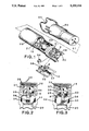
- FIG. 1 illustrates an exploded perspective view of the casing portion of the grooming clipper
- FIG. 2 illustrates a fragmentary top plan view showing the position of various components when the blades are in a central position
- FIG. 3 illustrates a view similar to FIG. 2 but illustrating the position of components when the blades are in the side position
- FIG. 4 illustrates a top sectional view of the coupling in the mid position
- FIG. 5 illustrates a top sectional view of the coupling in the left position
- FIG. 6 illustrates a top sectional view of the coupling in the right position
- FIG. 7 illustrates a top perspective view of the battery charging assembly
- FIG. 8 illustrates a top view of the battery pack assembly.
- the improved clipper includes an elongated clipper casing (15) that is easily held with one hand.
- This casing includes a clipper blade assembly (16) illustrated in FIGS. 2 through 3.
- the rear end of the casing (15) includes a motor shaft (20) and quick charge battery pack (60).
- the clipper casing (15) itself can be maintained and is easily maneuverable since the entire unit is self-contained.
- FIG. 1 details of the casing for the clipper without the clipper blade assembly (16) and inner portions thereof will be described.
- the upper half of the casing is shown exploded above the remaining portion to expose the interior.
- the front and rear ends of the casing (15) are indicated at (28) and (29) respectively, the clipper blade assembly holder is shown at (30) for holding the clipper blade assembly (16).
- the casing includes a quick charge battery pack (60) extending axial along the axis of the casing.
- the quick charge battery pack (60) consists of eight batteries and connects to the rear of the motor (20).
- a circuit board (21) connects the battery terminal to the motor (20).
- the motor (20) is attached to the casing by an attachment means such as bolts (44).
- the rear end of the motor shaft (31) is part of the motor gear assembly.
- the quick charge battery pack (60) has eight batteries. Seven AA size batteries (54) are circumferentially placed around a single AA (52) battery in the center. Two guides (61) on each side of the quick charge battery pack (60) formed by the slots (51) are placed longitudinally to align the batteries in the battery pack (60). The slots (51) also serve to align the battery pack (60) in the casing (15). Raised portions (53) along the inner circumference of the quick charge battery pack (60) and placed between the seven batteries (54) further keep the batteries firmly in place.
- a lever element (35) pivoted intermediate its ends for oscillating movement about a lever element shaft (8) normal to the axis of the motor shaft (31).
- the rear end of this lever element terminates in a cavity (36) receiving the eccentric disc (34) mounted on the off center shaft (32) of the motor shaft (31) so that rotation of the shaft (31) will result in the eccentric disc (34) bearing against the opposed walls of the cavity (36) to effect an oscillating movement of the lever element (35) by the eccentric disc (34).
- the cavity is shaped to accept the circular shaped eccentric disc (34).
- the receiving sides of the eccentric disc (34) are rounded to assure that when the drive finger (37) oscillates to one side and the other the eccentric disc (34) sides provide a surface sufficient to prevent wearing of either the eccentric disc (34) or receiving cavity (36).
- a bushing (45) is used to attach the eccentric disc (34) to the motor shaft (31) to allow the eccentric disc (34) to rotate if necessary.
- the bushing (45) allows movement along the axis of the off center shaft (32) as the motor shaft (31) rotates.
- the improved clipper has a change in oscillation speed at the end of the finger stroke.
- the change in speed occurs when the shaped bearing surface of the eccentric disc (34) engages the receiving cavity (36) as the finger moves outward and is engaged by the end of the eccentric disc (34).
- the bushing (45) is selected to substantially reduce friction and in combination with the rounded receiving cavity (36) eliminates the wear and heat generated as compared to other designs.
- the eccentric disc is shown in various positions when the eccentric disc (34) is in the center position, FIGS. 2 and 4, the center position of the rounded disc edge center (25) engages the receiving cavity midwall (24).
- the point of contact can be altered to change the motion of the receiving cavity (36) and thereby changing the speed of the movable blade teeth (39).
- the preferred embodiment uses near circular mating surfaces other designs are feasible. For example, more oblong eccentric disc (34) sides may be used as a shape.
- the forward end of the lever element (35) as shown in FIGS. 2 and 3 terminates in a drive finger (37) receivable in the clipper blade assembly (16) when the clipper blade assembly (16) is positioned in the clipper blade assembly holder (30).
- This drive finger (37) will move back and forth as a consequence of the above-described oscillation of the lever (35) to operate the clipper assembly (16).
- the clipper assembly (16) includes stationary blade teeth (38) and movable blade teeth (39). The improved movement of the finger (37) back and forth will cause the movable blade teeth (39) to oscillate back and forth relative to the stationary blade teeth (38) providing the desired shearing or cutting action of the clipper blades.
- the effect of the shape of the rounded eccentric disc (34) is to manipulate the timing and resulting motion of the movable blade teeth (39) on the clipper blade assembly (16).
- the pattern allows the hair to be trimmed more uniformly by feeding the hair smoothly and uniformly into the movable blade teeth (39) and stationary blade teeth (38).
- Small opposed felt-like pads (40) on either side of the central portion of the level element (35) will prevent hairs and the like from passing backwardly into the main portion of the casing.
- the main portion of the casing behind the felt-like pads (40) may be filled with appropriate lubricant.
- the improved basic clipper includes the lever element shaft (8) being supported at both the upper and the lower end of the lever element shaft (8).
- the lever element shaft (8) in the preferred embodiments is fixed to the cover (10) and snaps tightly into a lever receiving element slot (9).
- the eccentric disc (34) is shown in an upwardly extending position from the end of the shaft (31). In this position, the movable blade teeth (39) are in a central position relative to the stationary blade teeth (38) and the lever element (35) is in alignment with the axis of the motor shaft (31).
- FIG. 3 the relative positions of the various components described in FIG. 2 are shown after the shaft (31) has made a quarter turn in a clockwise direction as viewed in FIG. 3.
- this quarter turn will position the eccentric disc (34) to the right as viewed in FIG. 3, camming the rear end of the lever element (35) to the right so that the forward finger portion thereof will drive the movable blade teeth (39) to the left; that is, to one side as indicated in FIG. 3.
- the rounded edges of the eccentric disc (34) moving against the lever element (35) provides a sufficient surface to prevent the tendency for excess wear and noise caused by the squared edges of other non-rounded coupling. The reduced noise and vibration is especially significant for dealing with animals with sensitive hearing and sensitivity to conventional clippers.
- the movable blade teeth (39) will be moved back to a central position as indicated in FIG. 2 and a further quarter turn which will position the eccentric disc (34) to the left will then cause the movable blade teeth (39) to assume their right-hand-most position.
- the rounded edges of the eccentric disc (34) provides a sufficient surface to minimize wear, noise and vibration.
- the quick charge battery pack assembly charger (70) includes indicator (71), charger power switch (72) and a power cord (73).
- two switches are located in the rear of the quick charge battery pack (60).
- the location of the power switch at the rear provides the advantage of easy operation while placing the clipper power switch (75) away from the forward surface where they may be conducting operations.
- the clipper power switch (75) and speed control switch (76) turns the groomer on and off and provides two levels of cutter speed. Variable speed options can be easily adapted to the preferred embodiment.
- a quick charge battery pack assembly charger (70) that accepts the complete quick charge battery pack (60) provides ease of recharging the batteries.
- the handle (65) is shaped to provide a handle to withdraw the battery pack (60) assembly from the groomer, serve as a storage aid, prevent the groomer from rolling on an inclined flat surface when the groomer is placed on the surface.
Landscapes
- Life Sciences & Earth Sciences (AREA)
- Forests & Forestry (AREA)
- Engineering & Computer Science (AREA)
- Mechanical Engineering (AREA)
- Animal Behavior & Ethology (AREA)
- Animal Husbandry (AREA)
- Harvester Elements (AREA)
Abstract
Description
Claims (7)
Priority Applications (1)
| Application Number | Priority Date | Filing Date | Title |
|---|---|---|---|
| US07/877,529 US5259116A (en) | 1991-06-17 | 1992-05-01 | Animal grooming clipper |
Applications Claiming Priority (2)
| Application Number | Priority Date | Filing Date | Title |
|---|---|---|---|
| US71631691A | 1991-06-17 | 1991-06-17 | |
| US07/877,529 US5259116A (en) | 1991-06-17 | 1992-05-01 | Animal grooming clipper |
Related Parent Applications (1)
| Application Number | Title | Priority Date | Filing Date |
|---|---|---|---|
| US71631691A Continuation-In-Part | 1991-06-17 | 1991-06-17 |
Publications (1)
| Publication Number | Publication Date |
|---|---|
| US5259116A true US5259116A (en) | 1993-11-09 |
Family
ID=27109509
Family Applications (1)
| Application Number | Title | Priority Date | Filing Date |
|---|---|---|---|
| US07/877,529 Expired - Lifetime US5259116A (en) | 1991-06-17 | 1992-05-01 | Animal grooming clipper |
Country Status (1)
| Country | Link |
|---|---|
| US (1) | US5259116A (en) |
Cited By (18)
| Publication number | Priority date | Publication date | Assignee | Title |
|---|---|---|---|---|
| US6887244B1 (en) * | 1998-12-16 | 2005-05-03 | Medtronic, Inc. | Cordless surgical handpiece with disposable battery; and method |
| US20060207104A1 (en) * | 2005-03-18 | 2006-09-21 | Armando Alvite | Hair clipper with multiple speeds |
| US20090056137A1 (en) * | 2007-08-31 | 2009-03-05 | Terence Gordon Royle | Personal care apparatus |
| US20090056139A1 (en) * | 2007-08-31 | 2009-03-05 | Terence Gordon Royle | Hand held personal care appliance |
| WO2010121941A3 (en) * | 2009-04-20 | 2010-12-23 | Aesculap Suhl Gmbh | Animal shearing machine |
| US20110119930A1 (en) * | 2008-05-20 | 2011-05-26 | The Procter & Gamble Company | Electric Hair Cutting Machine |
| US20120240409A1 (en) * | 2011-03-22 | 2012-09-27 | Panasonic Corporation | Trimmer blade |
| US8418369B1 (en) * | 2003-10-07 | 2013-04-16 | Kim Laube | Clipper lever support insert |
| WO2013070828A1 (en) * | 2011-11-11 | 2013-05-16 | Sunbeam Products, Inc. | Electric hair cutting apparatus |
| US8484853B1 (en) * | 2005-08-29 | 2013-07-16 | Kim Laube | Hair cutting device with vacuum hair collection system |
| US8533962B1 (en) | 2009-01-07 | 2013-09-17 | Kim E. Laube | Clipper lever |
| AU2009249227B2 (en) * | 2008-05-20 | 2014-07-03 | Noxell Corporation | Electric hair cutting machine |
| US20170203450A1 (en) * | 2016-01-14 | 2017-07-20 | Nathan Hitson | Animal Shears/Clippers |
| US20180207817A1 (en) * | 2017-01-26 | 2018-07-26 | Panasonic Intellectual Property Management Co., Ltd. | Electric hair cutter |
| EP3424653A1 (en) * | 2017-07-07 | 2019-01-09 | Koninklijke Philips N.V. | Motion transmission unit, drive train and hair cutting appliance |
| US20220339808A1 (en) * | 2021-04-27 | 2022-10-27 | Wuhan Shernbao Pet Products Manufacturing Co., Ltd. | Electric Hair Clipper Driven by a Brushless External Rotor Motor |
| US20240208092A1 (en) * | 2022-12-21 | 2024-06-27 | Conair Llc | Multiple function hair trimmer |
| US20250339984A1 (en) * | 2024-05-03 | 2025-11-06 | WORX4U2, Inc. | Modular clippers |
Citations (8)
| Publication number | Priority date | Publication date | Assignee | Title |
|---|---|---|---|---|
| US3359635A (en) * | 1965-01-05 | 1967-12-26 | Sunbeam Corp | Electrically operated dry shaver |
| US4133733A (en) * | 1977-06-17 | 1979-01-09 | Envirotech Corporation | Electrolytic titration apparatus |
| US4592142A (en) * | 1982-08-27 | 1986-06-03 | Metabowerke Gmbh & Company | Guard device for hedging shears, and hedging shears |
| US4631825A (en) * | 1984-02-20 | 1986-12-30 | Sanyo Electric Co., Ltd. | Washable electric shaver |
| US4813133A (en) * | 1984-11-02 | 1989-03-21 | Remington Products, Inc. | Apparatus for a medical treatment preparation procedure |
| US4813136A (en) * | 1985-07-09 | 1989-03-21 | U.S. Philips Corporation | Dry shaver |
| US4845847A (en) * | 1987-01-14 | 1989-07-11 | Matsushita Electric Works, Ltd. | Dry shaver with a slidable trimmer handle |
| US4918819A (en) * | 1987-10-05 | 1990-04-24 | U.S. Philips Corp. | Electric shaving apparatus |
-
1992
- 1992-05-01 US US07/877,529 patent/US5259116A/en not_active Expired - Lifetime
Patent Citations (8)
| Publication number | Priority date | Publication date | Assignee | Title |
|---|---|---|---|---|
| US3359635A (en) * | 1965-01-05 | 1967-12-26 | Sunbeam Corp | Electrically operated dry shaver |
| US4133733A (en) * | 1977-06-17 | 1979-01-09 | Envirotech Corporation | Electrolytic titration apparatus |
| US4592142A (en) * | 1982-08-27 | 1986-06-03 | Metabowerke Gmbh & Company | Guard device for hedging shears, and hedging shears |
| US4631825A (en) * | 1984-02-20 | 1986-12-30 | Sanyo Electric Co., Ltd. | Washable electric shaver |
| US4813133A (en) * | 1984-11-02 | 1989-03-21 | Remington Products, Inc. | Apparatus for a medical treatment preparation procedure |
| US4813136A (en) * | 1985-07-09 | 1989-03-21 | U.S. Philips Corporation | Dry shaver |
| US4845847A (en) * | 1987-01-14 | 1989-07-11 | Matsushita Electric Works, Ltd. | Dry shaver with a slidable trimmer handle |
| US4918819A (en) * | 1987-10-05 | 1990-04-24 | U.S. Philips Corp. | Electric shaving apparatus |
Cited By (31)
| Publication number | Priority date | Publication date | Assignee | Title |
|---|---|---|---|---|
| US6887244B1 (en) * | 1998-12-16 | 2005-05-03 | Medtronic, Inc. | Cordless surgical handpiece with disposable battery; and method |
| US8418369B1 (en) * | 2003-10-07 | 2013-04-16 | Kim Laube | Clipper lever support insert |
| US20060207104A1 (en) * | 2005-03-18 | 2006-09-21 | Armando Alvite | Hair clipper with multiple speeds |
| US8484853B1 (en) * | 2005-08-29 | 2013-07-16 | Kim Laube | Hair cutting device with vacuum hair collection system |
| US20090056137A1 (en) * | 2007-08-31 | 2009-03-05 | Terence Gordon Royle | Personal care apparatus |
| US20090056139A1 (en) * | 2007-08-31 | 2009-03-05 | Terence Gordon Royle | Hand held personal care appliance |
| US7877880B2 (en) * | 2007-08-31 | 2011-02-01 | The Gillette Company | Hand held personal care appliance |
| US8141253B2 (en) * | 2007-08-31 | 2012-03-27 | The Gillette Company | Personal care assembly |
| US20110119930A1 (en) * | 2008-05-20 | 2011-05-26 | The Procter & Gamble Company | Electric Hair Cutting Machine |
| AU2009249227B2 (en) * | 2008-05-20 | 2014-07-03 | Noxell Corporation | Electric hair cutting machine |
| US8533962B1 (en) | 2009-01-07 | 2013-09-17 | Kim E. Laube | Clipper lever |
| US8769824B2 (en) | 2009-04-20 | 2014-07-08 | Aesculap Suhl Gmbh | Animal shearing machine |
| WO2010121941A3 (en) * | 2009-04-20 | 2010-12-23 | Aesculap Suhl Gmbh | Animal shearing machine |
| US20120240409A1 (en) * | 2011-03-22 | 2012-09-27 | Panasonic Corporation | Trimmer blade |
| CN104010777A (en) * | 2011-11-11 | 2014-08-27 | 光达家电用品公司 | Electric hair cutting apparatus |
| CN104010777B (en) * | 2011-11-11 | 2015-09-16 | 光达家电用品公司 | Electric hair device |
| US9346179B2 (en) | 2011-11-11 | 2016-05-24 | Sunbeam Products, Inc. | Electric hair cutting apparatus |
| WO2013070828A1 (en) * | 2011-11-11 | 2013-05-16 | Sunbeam Products, Inc. | Electric hair cutting apparatus |
| US20170203450A1 (en) * | 2016-01-14 | 2017-07-20 | Nathan Hitson | Animal Shears/Clippers |
| US10821617B2 (en) * | 2016-01-14 | 2020-11-03 | Nathan Hitson | Animal shears/clippers |
| US10737402B2 (en) * | 2017-01-26 | 2020-08-11 | Panasonic Intellectual Property Management Co., Ltd. | Electric hair cutter |
| US20180207817A1 (en) * | 2017-01-26 | 2018-07-26 | Panasonic Intellectual Property Management Co., Ltd. | Electric hair cutter |
| EP3424653A1 (en) * | 2017-07-07 | 2019-01-09 | Koninklijke Philips N.V. | Motion transmission unit, drive train and hair cutting appliance |
| CN110869176A (en) * | 2017-07-07 | 2020-03-06 | 皇家飞利浦有限公司 | Motion transfer units, drive trains and hair cutting appliances |
| JP2020526291A (en) * | 2017-07-07 | 2020-08-31 | コーニンクレッカ フィリップス エヌ ヴェKoninklijke Philips N.V. | Motion transmission unit, drive train, and hair cutting device |
| WO2019007864A1 (en) * | 2017-07-07 | 2019-01-10 | Koninklijke Philips N.V. | Motion transmission unit, drive train and hair cutting appliance |
| RU2756058C2 (en) * | 2017-07-07 | 2021-09-24 | Конинклейке Филипс Н.В. | Motion transmission unit, drive mechanism and hair cutting device |
| US11331820B2 (en) | 2017-07-07 | 2022-05-17 | Koninklijke Philips N.V. | Motion transmission unit, drive train and hair cutting appliance |
| US20220339808A1 (en) * | 2021-04-27 | 2022-10-27 | Wuhan Shernbao Pet Products Manufacturing Co., Ltd. | Electric Hair Clipper Driven by a Brushless External Rotor Motor |
| US20240208092A1 (en) * | 2022-12-21 | 2024-06-27 | Conair Llc | Multiple function hair trimmer |
| US20250339984A1 (en) * | 2024-05-03 | 2025-11-06 | WORX4U2, Inc. | Modular clippers |
Similar Documents
| Publication | Publication Date | Title |
|---|---|---|
| US5259116A (en) | Animal grooming clipper | |
| CN101432104B (en) | Cutting equipment and hair cutting devices | |
| EP0651978B1 (en) | Improvements in toothbrushes for personal hygiene purposes | |
| US4845847A (en) | Dry shaver with a slidable trimmer handle | |
| US4408623A (en) | Electrical manicuring device | |
| US6237178B1 (en) | Toothbrush comprising a brush member having bristles of different lengths, and brush member having bristles of different lengths for a tooth brush | |
| EP2170566B1 (en) | Grooming tool assembly | |
| US5193275A (en) | Flat-shaped dry shaver | |
| US8769824B2 (en) | Animal shearing machine | |
| AU3049195A (en) | Detachable pivoting clipper blades | |
| ATE234177T1 (en) | HAIR CUTTER | |
| US7114257B1 (en) | Multi purpose machine | |
| GB2383554A (en) | Hair clipper with pivoting handle | |
| US4710995A (en) | Electric motor driven toothbrush | |
| JPH05309184A (en) | Motor-driven razor | |
| US20080040927A1 (en) | Electric shaver and trimmer | |
| US4531291A (en) | Animal grooming clipper | |
| US3971130A (en) | Electric grass sickle-shear | |
| GB2234034A (en) | Drive mechanism for converting rotary motion into reciprocating linear motion | |
| AU2003290277A1 (en) | Hair clippers | |
| US3851388A (en) | Detachable blade assembly for grass shear | |
| GB2234033A (en) | Drive mechanism for converting rotary motion into reciprocating linear motion | |
| US20010003228A1 (en) | Electric shaving apparatus | |
| CN221338590U (en) | Flip type shaver | |
| EP1010488A3 (en) | A power saw with pivotal sole plate |
Legal Events
| Date | Code | Title | Description |
|---|---|---|---|
| REMI | Maintenance fee reminder mailed | ||
| FEPP | Fee payment procedure |
Free format text: PETITION RELATED TO MAINTENANCE FEES FILED (ORIGINAL EVENT CODE: PMFP); ENTITY STATUS OF PATENT OWNER: SMALL ENTITY |
|
| FP | Lapsed due to failure to pay maintenance fee |
Effective date: 19971112 |
|
| AS | Assignment |
Owner name: KIM LAUBE & COMPANY, INC., CALIFORNIA Free format text: ASSIGNMENT OF ASSIGNORS INTEREST;ASSIGNOR:LAUBE, KIM;REEL/FRAME:009556/0034 Effective date: 19950703 |
|
| FPAY | Fee payment |
Year of fee payment: 4 |
|
| SULP | Surcharge for late payment | ||
| FEPP | Fee payment procedure |
Free format text: PETITION RELATED TO MAINTENANCE FEES GRANTED (ORIGINAL EVENT CODE: PMFG); ENTITY STATUS OF PATENT OWNER: SMALL ENTITY |
|
| REMI | Maintenance fee reminder mailed | ||
| REIN | Reinstatement after maintenance fee payment confirmed | ||
| FP | Lapsed due to failure to pay maintenance fee |
Effective date: 20011109 |
|
| FEPP | Fee payment procedure |
Free format text: PETITION RELATED TO MAINTENANCE FEES FILED (ORIGINAL EVENT CODE: PMFP); ENTITY STATUS OF PATENT OWNER: SMALL ENTITY |
|
| FEPP | Fee payment procedure |
Free format text: PETITION RELATED TO MAINTENANCE FEES GRANTED (ORIGINAL EVENT CODE: PMFG); ENTITY STATUS OF PATENT OWNER: SMALL ENTITY |
|
| FPAY | Fee payment |
Year of fee payment: 8 |
|
| SULP | Surcharge for late payment | ||
| PRDP | Patent reinstated due to the acceptance of a late maintenance fee |
Effective date: 20030902 |
|
| STCF | Information on status: patent grant |
Free format text: PATENTED CASE |
|
| REMI | Maintenance fee reminder mailed | ||
| FPAY | Fee payment |
Year of fee payment: 12 |
|
| SULP | Surcharge for late payment |
Year of fee payment: 11 |