US5256995A - Low helium permeability atomic frequency standard cell and method for forming same - Google Patents
Low helium permeability atomic frequency standard cell and method for forming same Download PDFInfo
- Publication number
- US5256995A US5256995A US07/914,394 US91439492A US5256995A US 5256995 A US5256995 A US 5256995A US 91439492 A US91439492 A US 91439492A US 5256995 A US5256995 A US 5256995A
- Authority
- US
- United States
- Prior art keywords
- cell
- windows
- tube
- helium
- opening
- Prior art date
- Legal status (The legal status is an assumption and is not a legal conclusion. Google has not performed a legal analysis and makes no representation as to the accuracy of the status listed.)
- Expired - Lifetime
Links
- 229910052734 helium Inorganic materials 0.000 title claims abstract description 59
- SWQJXJOGLNCZEY-UHFFFAOYSA-N helium atom Chemical compound [He] SWQJXJOGLNCZEY-UHFFFAOYSA-N 0.000 title claims abstract description 59
- 239000001307 helium Substances 0.000 title claims abstract description 58
- 230000035699 permeability Effects 0.000 title claims abstract description 23
- 238000000034 method Methods 0.000 title claims description 20
- 239000011521 glass Substances 0.000 claims abstract description 38
- 238000007789 sealing Methods 0.000 claims abstract description 24
- 239000005354 aluminosilicate glass Substances 0.000 claims abstract description 13
- 238000010438 heat treatment Methods 0.000 claims abstract description 10
- 239000005388 borosilicate glass Substances 0.000 claims abstract description 9
- 210000004027 cell Anatomy 0.000 claims description 113
- 239000007789 gas Substances 0.000 claims description 18
- 239000000463 material Substances 0.000 claims description 12
- IGLNJRXAVVLDKE-UHFFFAOYSA-N rubidium atom Chemical compound [Rb] IGLNJRXAVVLDKE-UHFFFAOYSA-N 0.000 claims description 10
- 229910052701 rubidium Inorganic materials 0.000 claims description 9
- 210000005056 cell body Anatomy 0.000 claims description 8
- 229910052783 alkali metal Inorganic materials 0.000 claims description 5
- 150000001340 alkali metals Chemical class 0.000 claims description 5
- 239000000203 mixture Substances 0.000 claims 1
- 230000032683 aging Effects 0.000 description 12
- 238000004519 manufacturing process Methods 0.000 description 11
- 238000013459 approach Methods 0.000 description 6
- 239000001257 hydrogen Substances 0.000 description 5
- 229910052739 hydrogen Inorganic materials 0.000 description 5
- UFHFLCQGNIYNRP-UHFFFAOYSA-N Hydrogen Chemical compound [H][H] UFHFLCQGNIYNRP-UHFFFAOYSA-N 0.000 description 4
- 230000007423 decrease Effects 0.000 description 4
- 238000007511 glassblowing Methods 0.000 description 4
- 230000005855 radiation Effects 0.000 description 4
- 229910052792 caesium Inorganic materials 0.000 description 3
- TVFDJXOCXUVLDH-UHFFFAOYSA-N caesium atom Chemical compound [Cs] TVFDJXOCXUVLDH-UHFFFAOYSA-N 0.000 description 3
- 229910052751 metal Inorganic materials 0.000 description 3
- 239000002184 metal Substances 0.000 description 3
- 230000003287 optical effect Effects 0.000 description 3
- IJGRMHOSHXDMSA-UHFFFAOYSA-N Atomic nitrogen Chemical compound N#N IJGRMHOSHXDMSA-UHFFFAOYSA-N 0.000 description 2
- 238000010521 absorption reaction Methods 0.000 description 2
- 125000004429 atom Chemical group 0.000 description 2
- 230000006870 function Effects 0.000 description 2
- 150000002431 hydrogen Chemical class 0.000 description 2
- 238000000926 separation method Methods 0.000 description 2
- 238000009825 accumulation Methods 0.000 description 1
- 239000003513 alkali Substances 0.000 description 1
- -1 and Substances 0.000 description 1
- 239000011324 bead Substances 0.000 description 1
- 239000011230 binding agent Substances 0.000 description 1
- 230000003915 cell function Effects 0.000 description 1
- 210000002421 cell wall Anatomy 0.000 description 1
- 230000002860 competitive effect Effects 0.000 description 1
- 238000010276 construction Methods 0.000 description 1
- 238000011109 contamination Methods 0.000 description 1
- 238000001816 cooling Methods 0.000 description 1
- 239000013078 crystal Substances 0.000 description 1
- 238000005065 mining Methods 0.000 description 1
- 238000012986 modification Methods 0.000 description 1
- 230000004048 modification Effects 0.000 description 1
- 229910052757 nitrogen Inorganic materials 0.000 description 1
- 239000002245 particle Substances 0.000 description 1
- 239000012466 permeate Substances 0.000 description 1
- 239000000843 powder Substances 0.000 description 1
- 238000003825 pressing Methods 0.000 description 1
- 230000008569 process Effects 0.000 description 1
- 239000010453 quartz Substances 0.000 description 1
- 239000011819 refractory material Substances 0.000 description 1
- VYPSYNLAJGMNEJ-UHFFFAOYSA-N silicon dioxide Inorganic materials O=[Si]=O VYPSYNLAJGMNEJ-UHFFFAOYSA-N 0.000 description 1
- 125000006850 spacer group Chemical group 0.000 description 1
- 229910001220 stainless steel Inorganic materials 0.000 description 1
- 239000010935 stainless steel Substances 0.000 description 1
- 239000000126 substance Substances 0.000 description 1
- 239000012808 vapor phase Substances 0.000 description 1
Images


Classifications
-
- C—CHEMISTRY; METALLURGY
- C03—GLASS; MINERAL OR SLAG WOOL
- C03B—MANUFACTURE, SHAPING, OR SUPPLEMENTARY PROCESSES
- C03B23/00—Re-forming shaped glass
- C03B23/20—Uniting glass pieces by fusing without substantial reshaping
-
- G—PHYSICS
- G04—HOROLOGY
- G04F—TIME-INTERVAL MEASURING
- G04F5/00—Apparatus for producing preselected time intervals for use as timing standards
- G04F5/14—Apparatus for producing preselected time intervals for use as timing standards using atomic clocks
Definitions
- This invention relates to atomic frequency standard cells such as cesium and rubidium cells, and to methods for fabricating such cells.
- Optically pumped atomic frequency standards using alkali metal such as cesium and rubidium vapor have come into wide spread use as basic frequency standards.
- Weidemann U.S. Pat. No. 4,661,782 provides a general introduction to such frequency standards.
- a gas cell is provided within a resonant microwave cavity.
- microwave resonance in the rubidium is detected by measuring the absorption of a suitable optical radiation which is directed at the gas cell while the resonant cavity is excited by externally generated microwave radiation.
- the frequency of this microwave radiation is controlled according to the degree of absorption of the optical radiation.
- the cell initially has no helium inside, then helium from the atmosphere will slowly pass through the glass and the helium density inside the cell will increase with time. The density increases to a final steady-state value which is equal to the density of helium in the atmosphere. At this point the permeation of helium through the glass stops because there is no longer any pressure differential across the glass walls of the cell. Typically this process takes years to stabilize, and the permeation rate is largest at the start.
- the rate at which helium accumulates in a cell depends on the total permeation rate (atoms/sec) and the volume.
- the permeation rate is proportional to the total surface area of the cell.
- a cell is made smaller, its volume to surface area ratio decreases; i.e., the volume fills up faster with helium in a smaller cell because there is proportionally more surface area available for permeation.
- the need for glass with lower helium permeability becomes more important.
- an atomic frequency standard cell comprising a cell body defining first and second annular sealing surfaces. First and second windows are sealed to respective ones of the sealing surfaces to form a cell, and a fill tube communicates with an opening in the cell and is sealed thereto.
- This cell preferably has a volume less than 60 cubic centimeters.
- a method for forming an atomic frequency standard cell having low helium permeability.
- First and second windows and a cell body are provided, the body defining first and second annular sealing surfaces, and one of the windows and the body defining an opening.
- the first and second windows are sealed to the respective sealing surfaces of the body to form a cell having a volume no greater than 60 cubic centimeters.
- a tube is sealed to the cell adjacent to the opening to form a fill tube for the cell.
- the body, windows and tube comprise aluminosilicate glass, and annular fusible gaskets comprising borosilicate glasses are positioned between the windows and the respective annular sealing surfaces.
- the sealing step preferably comprises a step of heating the body and the windows to a temperature of no more than about 850° C. for a time sufficient to fuse the gaskets and seal the windows to the body.
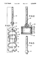
- FIG. 1 is an exploded perspective view of the components of an atomic frequency standard cell which incorporates a presently preferred embodiment of this invention, prior to fabrication.
- FIG. 2 is a cross-sectional view of the cell of FIG. 1 at the completion of fabrication.
- FIG. 3 is a perspective view of the cell of FIG. 2 at a first intermediate stage of fabrication.
- FIG. 4 is a cross-sectional view taken along line 4--4 of FIG. 3.
- FIG. 5 is a perspective view of selected components of the cell of FIG. 2 at a second intermediate stage in fabrication.
- FIG. 6 is a side view in partial section of the cell of FIG. 2 at a third intermediate stage in fabrication.
- FIG. 7 is a graph showing a preferred heating cycle used in the fabrication of the cell of FIG. 2.
- FIGS. 1 and 2 show exploded perspective and cross sectional views of an atomic frequency standard cell 10 which incorporates a presently preferred embodiment of this invention.
- the cell 10 includes a cylindrical, tubular body 12 which defines spaced, parallel, annular sealing surfaces 14.
- the cell 10 also includes first and second windows 16, one of which defines a central opening 18.
- Annular, fusible window gaskets 20 are positioned between the sealing surfaces 14 and the windows 16, and a fill tube 22 is positioned in the opening 18.
- a fusible tubular gasket 24 is positioned around the fill tube 22 to seal the fill tube 22 to the adjacent window 16.
- the various component elements of the cell 10 can readily be manufactured as discrete components.
- the fill tube 22, the body 12 and the gaskets 20, 24 can be cut from glass tubes.
- the materials chosen for the elements of the cell 10 are carefully selected to have the desired thermal and helium permeability characteristics.
- the gaskets 20, 24 are formed of materials having a lower softening temperature than that of the body 12, the windows 16 and the tube 22 such that when the assembled cell 10 is heated to the proper temperature, the gaskets 20, 24 fuse to seal the windows 16 to the body 12 and the fill tube 22 to the window 16, and yet the body 12, the windows 16 and the tube 22 do not substantially alter their shape.
- FIGS. 3-6 The preferred method for forming the cell 10 is illustrated in FIGS. 3-6.
- a first step in this method is to assemble the windows 16, window gaskets 20 and body 12 in a stack on a support element 30.
- the assembled components are placed within a jig 32, 34 which is loosely held together by fasteners 36.
- the support surface 30 is oriented horizontally such that the windows 16 are oriented horizontally.
- the jig 32, 34 can be pressed together to position the body 12, the windows 16 and the window gaskets 20 concentric with respect to one another.
- the jig 32, 34 is then moved out of contact with the assembled elements of the cell 10.
- the assembly shown in FIGS. 3 and 4 is then brought to a suitable temperature to cause the window gaskets 20 to fuse and thereby to seal the windows 16 to the body 12.
- the sealed assembly is then allowed to cool at a controlled rate to anneal the assembly.
- the next step in the fabrication of the cell 10 is to place the tube gasket 24 on the fill tube 22 and to support the fill tube in a horizontal orientation, with the tube gasket 24 spaced from the end of the fill tube 22 by a small amount (1 mm in this example). Then the combination of the fill tube 22 and the assembled tube gasket 24 is heated as described above to cause the tube gasket 24 to fuse to form a bead like shape at one end of the fill tube 22. As shown in FIG. 5, a small length (approximately 1/2 mm in this embodiment) of the fill tube 22 protrudes beyond the fused tube gasket 24.
- the third step in the preferred method for forming the cell 10 is to place the body 12 with the sealed windows 16 in place in a fixture 40 which includes a support surface 42.
- the fixture 40 supports two vertical supports 44 which are provided with adjustable flanges 46.
- the fill tube 22 is positioned with the end of the fill tube 22 in the opening 18 and the fused tube gasket 24 in contact with the adjacent window 16.
- the upper end of the fill tube 22 is positioned within a riser 48 that defines a head 50.
- the riser 48 is freely slidable in an opening in a beam 52 which rests on the flanges 46.
- the fixture 40 is adjusted such that the head 50 of the riser 48 protrudes approximately 1 mm above the beam 52.
- the weight of the riser 48 presses the fill tube 22 downwardly, thereby pressing the fused tube gasket 24 into contact with the window 16. This assembly is then heated as described above, thereby softening the tube gasket 24. Once the tube gasket 24 is softened, the weight of the riser 48 pushes the fill tube 24 downwardly by about 1 mm and thereby presses the fused tube gasket 24 into sealing contact with the adjacent window 16, to produce the finished cell 10 of FIG. 2.
- K is the helium permeation constant which is the permeability in cc of helium per second at NTP (760 torr, 25° C.) for 1 cm 2 of glass having a thickness of 1 mm when a helium partial pressure difference of 1 torr is applied across the glass
- A is the total surface area of glass in cm 2
- V is in cc
- d is in mm
- T is the cell temperature in degrees Kelvin.
- ⁇ p o is the initial value of the helium partial pressure difference across the cell wall, which is positive if the helium pressure outside the cell is greater than that inside.
- ⁇ is a long time, on the order of years. For this reason the aging when the unit is new is of primary interest, which is also when the aging rate is greatest.
- this equation can be used to set an upper limit on the permeation constant as a function of the surface-area-to-volume ratio and the glass thickness:
- a military RFS typically either uses a cell that operates at high temperature ( ⁇ 100° C.), or else uses a thermoelectric cooler to maintain a lower cell temperature when higher ambient temperatures are encountered.
- the latter approach is more complicated and expensive, and therefore the former approach of a cell able to operate at high temperatures is desirable. For this reason, a cell operating temperature of 100° C. is assumed in the following analysis.
- Aluminosilicate glass such as Corning 1720 glass has a low enough helium permeation constant to satisfy the requirement of Eq. (14), and it satisfies the requirements by more than two orders of magnitude; since other aluminosilicate glasses are expected to have approximately the same helium permeation constant as Corning 1720, they are also expected to be suitable for use in small cells.
- Eq. (11) which gives the maximum allowable value of the permeation constant as a function of (A/V) and d.
- Eq. (11) can be used to determine the smallest allowable value of (A/V)/d.
- the preferred material for the body 12, the window 16 and the fill tube 22 is an aluminosilicate glass such as Corning 1720 or 1724.
- the preferred material for the gaskets 20, 24 is a borosilicate glass such as Corning 7052.
- Borosilicate glass has a lower softening point than does aluminosilicate glass, and thus is well suited for forming the sealing gaskets 20, 24. Additionally, the coefficients of thermal expansion of these two materials are closely matched.
- Aluminosilicate glass has a suitably low helium permeability constant K(T) (less than 2 ⁇ 10 -13 for T equals 100° C.). Borosilicate glass, though it has a higher helium permeability constant, makes up only a small fraction of the total area of the cell 10.
- Table 1 provides presently preferred dimensions and materials for the components of the cell 10, which has a volume of about 0.66 cc. In Table 1 all dimensions are in inches, and the dimensions for the gaskets 20, 24 are taken after fabrication of the cell 10 has been completed.
- the heating cycle is preferably conducted at a relatively low temperature of less than 850° C. and preferably about 845° C. for about one hour.
- FIG. 7 defines the preferred heating cycle used for the three sealing operations described above.
- the cooling rate is preferably controlled to allow at least seven minutes in the anneal range for aluminosilicate glass (660°-750° C.) and at least seven minutes in the anneal range for borosilicate glass (430°-500° C.) Vibration is preferably minimized during the heating cycle, and a travelling belt furnace can be used
- the surfaces to be sealed should be clean and free of particle contamination.
- the preferred material for the support surfaces 30, 42, the jig 32, 34, and the beam 52 is a refractory material such as that sold under the trade name Lava by Minnesota Mining & Manufacturing.
- the remaining components of the fixture 40 can be formed of stainless steel.
- the cell After the cell has been fabricated as discussed above, it can be filled in the conventional manner with a gas comprising an alkali metal vapor such as cesium or rubidium vapor.
- a gas comprising an alkali metal vapor such as cesium or rubidium vapor.
- the fill tube 22 can then be sealed in the conventional manner to close the cell 10.
- the cell 10 and the method for forming the cell 10 described above provide a number of important advantages.
- all of the component parts can be manufactured separately in automatic or semi-automatic operations.
- the cell itself can be manufactured in a low cost, repeatable manner without the use of specialized glass-blowing skills Because the body of the cell functions as a spacer which defines the separation between the windows and therefore the optical path length of the cell, the separation between the windows can be precisely controlled at a desired value simply by properly dimensioning the component parts.
- the fill tube allows the cell to be filled in the conventional manner without glass blowing skills, and the sealed cell provides low helium permeability and is well suited for a small volume cell.
- the windows are flat and free of thermal deformation, and much of the window that receives the fill tube is itself unobstructed. This invention is particularly useful in small volume cells having a volume less than 60 cc, and preferably less than 10 cc.
- the cell 10 can be shaped as desired.
- cross-sectional shapes other than the circular shape shown can readily be obtained.
- the fill tube can be mounted in an opening in the body as opposed to one of the windows, and the fill tube may not protrude into the opening.
- pressed sintered parts made from glass powder and a suitable binder may be used.
Landscapes
- Chemical & Material Sciences (AREA)
- Engineering & Computer Science (AREA)
- Materials Engineering (AREA)
- Organic Chemistry (AREA)
- Physics & Mathematics (AREA)
- General Physics & Mathematics (AREA)
- Stabilization Of Oscillater, Synchronisation, Frequency Synthesizers (AREA)
- Sealing Battery Cases Or Jackets (AREA)
Abstract
Description
______________________________________
U.S. Pat. No.       Inventor
______________________________________
3,242,423           L. Malnar
3,248,666           D. J. Farmer
3,510,758           G. R. Huggett
3,577,069           L. Malnar
3,675,067           H. Brun
4,405,905           Busca et al.
4,494,085           S. Goldberg
4,569,962           H. Robinson
______________________________________
q(T,t)=K(T)·(A/d)·δp·t, (1)
dp/dt=δp/τ, (2)
τ=0.392·V·d/[K(T)·A·T].(3)
y=C.sub.1 ·p, (4)
C.sub.1 ≈+0.80×10.sup.-7 /torr @ 100° C.(5)
R(t)≡dy(t)/dt=[C.sub.1 ·δp.sub.o /τ]·e.sup.-1/τ (6)
R.sub.o ≡R(O)=C.sub.1 ·δp.sub.o /τ,(7)
R.sub.o =2.04×10.sup.-7 ·[δp.sub.o ·K(T)·A·T]/(V·d). (8)
R.sub.o =8.16×10.sup.-10 ·[K(T)·A·T]/(V·d). (9)
K(T)≦(1.23×10.sup.9 ·R.sub.o /T)·d/(A/V).(10)
K(T)≦1.25×10.sup.-12 ·d/(A/V). (11)
A/V=2(1/L+1/R), cylindrical cell. (12)
K(T)≦1.9×10.sup.-13 ·d. (13)
K(T)≦1.9×10.sup.-13, d=1 mm. (14)
              TABLE 1
______________________________________
                 Wall
Element Height   Thickness  ID    OD    Material*
______________________________________
body 12 .220     .040       --    .52   1
window 16
        .040     --         --    .52   1
fill tube 22
        2.0      --         .040   .080 1
window  .030     .040       --    .52   2
gasket 20
fill tube
        .060     --         .080  .19   2
gasket 24
______________________________________
 *Material 1 is an aluminosilicate glass such as Corning 1724; Material 2
 is a borosilicate glass such as Corning 7052 or 7056.
Claims (21)
Priority Applications (10)
| Application Number | Priority Date | Filing Date | Title |
|---|---|---|---|
| US07/914,394 US5256995A (en) | 1992-07-17 | 1992-07-17 | Low helium permeability atomic frequency standard cell and method for forming same |
| CA002098966A CA2098966A1 (en) | 1992-07-17 | 1993-06-22 | Atomic frequency standard cell and method for forming same |
| TW082105398A TW226491B (en) | 1992-07-17 | 1993-07-06 | |
| JP5173875A JPH06204586A (en) | 1992-07-17 | 1993-07-14 | Atomic frequency reference cell and its manufacture |
| KR1019930013406A KR940002868A (en) | 1992-07-17 | 1993-07-16 | Atomic Frequency Standard Cell and Manufacturing Method Thereof |
| CN93108899A CN1084325A (en) | 1992-07-17 | 1993-07-16 | The atomic frequency standard Battery And Its Manufacturing Methods |
| AT93111560T ATE161637T1 (en) | 1992-07-17 | 1993-07-19 | ATOMIC FREQUENCY NORMAL CELL AND METHOD FOR PRODUCING IT |
| EP93111560A EP0579259B1 (en) | 1992-07-17 | 1993-07-19 | Atomic frequency standard cell and method for forming same |
| DE69315900T DE69315900T2 (en) | 1992-07-17 | 1993-07-19 | Atomic frequency normal cell and method for its production |
| ES93111560T ES2112359T3 (en) | 1992-07-17 | 1993-07-19 | ATOMIC FREQUENCY PATTERN CELL AND METHOD FOR FORMING IT. |
Applications Claiming Priority (1)
| Application Number | Priority Date | Filing Date | Title |
|---|---|---|---|
| US07/914,394 US5256995A (en) | 1992-07-17 | 1992-07-17 | Low helium permeability atomic frequency standard cell and method for forming same |
Publications (1)
| Publication Number | Publication Date |
|---|---|
| US5256995A true US5256995A (en) | 1993-10-26 |
Family
ID=25434300
Family Applications (1)
| Application Number | Title | Priority Date | Filing Date |
|---|---|---|---|
| US07/914,394 Expired - Lifetime US5256995A (en) | 1992-07-17 | 1992-07-17 | Low helium permeability atomic frequency standard cell and method for forming same |
Country Status (10)
| Country | Link |
|---|---|
| US (1) | US5256995A (en) |
| EP (1) | EP0579259B1 (en) |
| JP (1) | JPH06204586A (en) |
| KR (1) | KR940002868A (en) |
| CN (1) | CN1084325A (en) |
| AT (1) | ATE161637T1 (en) |
| CA (1) | CA2098966A1 (en) |
| DE (1) | DE69315900T2 (en) |
| ES (1) | ES2112359T3 (en) |
| TW (1) | TW226491B (en) |
Cited By (5)
| Publication number | Priority date | Publication date | Assignee | Title |
|---|---|---|---|---|
| US9117563B2 (en) | 2014-01-13 | 2015-08-25 | Cold Quanta, Inc. | Ultra-cold-matter system with thermally-isolated nested source cell |
| US9467157B2 (en) | 2014-09-08 | 2016-10-11 | Seiko Epson Corporation | Atomic cell, atomic cell manufacturing method, quantum interference device, atomic oscillator, electronic device, and moving object |
| US9960025B1 (en) | 2013-11-11 | 2018-05-01 | Coldquanta Inc. | Cold-matter system having ion pump integrated with channel cell |
| US9960026B1 (en) | 2013-11-11 | 2018-05-01 | Coldquanta Inc. | Ion pump with direct molecule flow channel through anode |
| US10509369B1 (en) | 2018-04-05 | 2019-12-17 | The Government Of The United States Of America As Represented By The Secretary Of The Air Force | Method of manufacturing a vapor cell for alkaline-earth-like atoms inside an ultrahigh vacuum chamber |
Families Citing this family (8)
| Publication number | Priority date | Publication date | Assignee | Title |
|---|---|---|---|---|
| KR960006319B1 (en) * | 1994-06-30 | 1996-05-13 | 이승우 | Chewing gum with pilocarpine |
| JPH0819368A (en) * | 1994-07-07 | 1996-01-23 | Shiyuushichi Takahashi | Taste-improving agent for coffee |
| US6165516A (en) * | 1996-11-27 | 2000-12-26 | Wm. Wrigley Jr. Company | Method of controlling release of caffeine in chewing gum |
| EP1181010A4 (en) | 1999-04-06 | 2003-03-26 | Wrigley W M Jun Co | Pharmaceutical chewing gum formulations |
| KR20020038160A (en) * | 2000-11-16 | 2002-05-23 | 황성연 | Manufacturing method of gum for cleaning oral |
| US20070059420A1 (en) * | 2005-09-13 | 2007-03-15 | Catani Steven J | Sweetener and aroma compositions |
| JPWO2021024619A1 (en) * | 2019-08-06 | 2021-02-11 | ||
| JP7583352B2 (en) * | 2020-06-04 | 2024-11-14 | 日本電気硝子株式会社 | Glass for atomic cells, atomic cells, and method for manufacturing atomic cells |
Citations (9)
| Publication number | Priority date | Publication date | Assignee | Title |
|---|---|---|---|---|
| US3242423A (en) * | 1962-01-10 | 1966-03-22 | Csf | Resonance cells for optical pumping |
| US3248666A (en) * | 1963-03-12 | 1966-04-26 | Gtc Kk | Optically pumped combination gas cell and microwave resonating cavity |
| US3510758A (en) * | 1967-11-14 | 1970-05-05 | Varian Associates | Atomic resonance gas cell having an evacuated double end wall structure |
| US3577069A (en) * | 1968-02-05 | 1971-05-04 | Csf | Optical resonance cells containing an alloy of an alkali metal with another metal |
| US3675067A (en) * | 1968-02-02 | 1972-07-04 | Csf | Optical resonance cell with means for regulating internal vapor pressure |
| US4405905A (en) * | 1980-01-11 | 1983-09-20 | Oscilloquartz S.A. | Atomic frequency standard having microwave loop around absorption cell |
| US4494085A (en) * | 1982-04-28 | 1985-01-15 | Eg&G, Inc. | Miniaturized atomic frequency standard having both filter cell and absorption cell in resonator cavity |
| US4596962A (en) * | 1983-11-03 | 1986-06-24 | Duke University | Evacuated, wall-coated, sealed, alkali atom cell for an atomic frequency standard |
| US4661782A (en) * | 1985-11-25 | 1987-04-28 | Ball Corporation | Integrated microwave cavity resonator and magnetic shield for an atomic frequency standard |
Family Cites Families (3)
| Publication number | Priority date | Publication date | Assignee | Title |
|---|---|---|---|---|
| US3942993A (en) * | 1968-05-18 | 1976-03-09 | U.S. Philips Corporation | Method of sealing adjoining parts of an evacuated vessel with solder glass |
| GB2106890B (en) * | 1981-09-14 | 1984-11-14 | Philips Electronic Associated | Method of making electron tube envelope assemblies |
| US4706043A (en) * | 1986-05-23 | 1987-11-10 | Ball Corporation | Frequency standard using hydrogen maser |
-
1992
- 1992-07-17 US US07/914,394 patent/US5256995A/en not_active Expired - Lifetime
-
1993
- 1993-06-22 CA CA002098966A patent/CA2098966A1/en not_active Abandoned
- 1993-07-06 TW TW082105398A patent/TW226491B/zh active
- 1993-07-14 JP JP5173875A patent/JPH06204586A/en active Pending
- 1993-07-16 KR KR1019930013406A patent/KR940002868A/en not_active Ceased
- 1993-07-16 CN CN93108899A patent/CN1084325A/en active Pending
- 1993-07-19 ES ES93111560T patent/ES2112359T3/en not_active Expired - Lifetime
- 1993-07-19 AT AT93111560T patent/ATE161637T1/en not_active IP Right Cessation
- 1993-07-19 DE DE69315900T patent/DE69315900T2/en not_active Expired - Fee Related
- 1993-07-19 EP EP93111560A patent/EP0579259B1/en not_active Expired - Lifetime
Patent Citations (9)
| Publication number | Priority date | Publication date | Assignee | Title |
|---|---|---|---|---|
| US3242423A (en) * | 1962-01-10 | 1966-03-22 | Csf | Resonance cells for optical pumping |
| US3248666A (en) * | 1963-03-12 | 1966-04-26 | Gtc Kk | Optically pumped combination gas cell and microwave resonating cavity |
| US3510758A (en) * | 1967-11-14 | 1970-05-05 | Varian Associates | Atomic resonance gas cell having an evacuated double end wall structure |
| US3675067A (en) * | 1968-02-02 | 1972-07-04 | Csf | Optical resonance cell with means for regulating internal vapor pressure |
| US3577069A (en) * | 1968-02-05 | 1971-05-04 | Csf | Optical resonance cells containing an alloy of an alkali metal with another metal |
| US4405905A (en) * | 1980-01-11 | 1983-09-20 | Oscilloquartz S.A. | Atomic frequency standard having microwave loop around absorption cell |
| US4494085A (en) * | 1982-04-28 | 1985-01-15 | Eg&G, Inc. | Miniaturized atomic frequency standard having both filter cell and absorption cell in resonator cavity |
| US4596962A (en) * | 1983-11-03 | 1986-06-24 | Duke University | Evacuated, wall-coated, sealed, alkali atom cell for an atomic frequency standard |
| US4661782A (en) * | 1985-11-25 | 1987-04-28 | Ball Corporation | Integrated microwave cavity resonator and magnetic shield for an atomic frequency standard |
Non-Patent Citations (2)
| Title |
|---|
| Thomas C. English and Ernst Jechart; Proc. 35th Ann. Freq Control Symposium, USAERADCOM, Ft. Monmouth, N.J., 07703, May 1991 "Development of a Sapphire Lamp for Use in Satellite-Borne Atomic Rubidium Clocks"; Eframtom Systems Corporation, Irvine, California 92715, pp. 637-645. |
| Thomas C. English and Ernst Jechart; Proc. 35th Ann. Freq Control Symposium, USAERADCOM, Ft. Monmouth, N.J., 07703, May 1991 Development of a Sapphire Lamp for Use in Satellite Borne Atomic Rubidium Clocks ; Eframtom Systems Corporation, Irvine, California 92715, pp. 637 645. * |
Cited By (5)
| Publication number | Priority date | Publication date | Assignee | Title |
|---|---|---|---|---|
| US9960025B1 (en) | 2013-11-11 | 2018-05-01 | Coldquanta Inc. | Cold-matter system having ion pump integrated with channel cell |
| US9960026B1 (en) | 2013-11-11 | 2018-05-01 | Coldquanta Inc. | Ion pump with direct molecule flow channel through anode |
| US9117563B2 (en) | 2014-01-13 | 2015-08-25 | Cold Quanta, Inc. | Ultra-cold-matter system with thermally-isolated nested source cell |
| US9467157B2 (en) | 2014-09-08 | 2016-10-11 | Seiko Epson Corporation | Atomic cell, atomic cell manufacturing method, quantum interference device, atomic oscillator, electronic device, and moving object |
| US10509369B1 (en) | 2018-04-05 | 2019-12-17 | The Government Of The United States Of America As Represented By The Secretary Of The Air Force | Method of manufacturing a vapor cell for alkaline-earth-like atoms inside an ultrahigh vacuum chamber |
Also Published As
| Publication number | Publication date |
|---|---|
| TW226491B (en) | 1994-07-11 |
| EP0579259A1 (en) | 1994-01-19 |
| CA2098966A1 (en) | 1994-01-18 |
| KR940002868A (en) | 1994-02-19 |
| ES2112359T3 (en) | 1998-04-01 |
| EP0579259B1 (en) | 1997-12-29 |
| DE69315900D1 (en) | 1998-02-05 |
| CN1084325A (en) | 1994-03-23 |
| DE69315900T2 (en) | 1998-07-30 |
| JPH06204586A (en) | 1994-07-22 |
| ATE161637T1 (en) | 1998-01-15 |
Similar Documents
| Publication | Publication Date | Title |
|---|---|---|
| US5256995A (en) | Low helium permeability atomic frequency standard cell and method for forming same | |
| Liew et al. | Microfabricated alkali atom vapor cells | |
| US8684650B2 (en) | Methods for introduction of a reactive material into a vacuum chamber | |
| CA1243642A (en) | Method of forming capsules containing a precise amount of material | |
| Douahi et al. | Vapour microcell for chip scale atomic frequency standard | |
| US8546748B2 (en) | Helium barrier atom chamber | |
| Straessle et al. | Low-temperature indium-bonded alkali vapor cell for chip-scale atomic clocks | |
| CA1041206A (en) | Laser tube mirror assembly | |
| US5530408A (en) | Method of making an oven controlled crystal oscillator the frequency of which remains ultrastable under temperature variations | |
| Overstolz et al. | Wafer scale fabrication of highly integrated rubidium vapor cells | |
| Knappe et al. | Compact atomic vapor cells fabricated by laser-induced heating of hollow-core glass fibers | |
| US3889207A (en) | Frequency stabilized gas laser | |
| US4666251A (en) | Large aperture, very high temperature, hermetically sealed optical windows | |
| US3771066A (en) | Gas laser | |
| Quinn et al. | A new type of iodine cell for stabilized lasers | |
| Piltch et al. | High temperature alumina discharge tube for pulsed metal vapor lasers | |
| US4082392A (en) | Gas discharge lamp preparation process | |
| Gorecki | Development of first European chip-scale atomic clocks: Technologies, assembling and metrology | |
| Ishikawa | Noble-gas performance for lithium atomic spectroscopy in glass vapor cells | |
| Liew et al. | Micromachined alkali atom vapor cells for chip-scale atomic clocks | |
| JP2018120977A (en) | Atomic cell, quantum interference device, atomic oscillator, electronic device, and moving object | |
| JPH0432262B2 (en) | ||
| Center et al. | Carbon monoxide laser | |
| Altman et al. | Hot window, metal vapor tube | |
| Debe et al. | Design and performance of a vapor transport cell for operation onboard the Space Shuttle Orbiter |
Legal Events
| Date | Code | Title | Description |
|---|---|---|---|
| AS | Assignment |
Owner name: BALL CORPORATION A CORP. OF IN, INDIANA Free format text: ASSIGNMENT OF ASSIGNORS INTEREST.;ASSIGNOR:SCHOLES, ADDISON B.;REEL/FRAME:006195/0463 Effective date: 19920716 |
|
| STCF | Information on status: patent grant |
Free format text: PATENTED CASE |
|
| AS | Assignment |
Owner name: WELLS FARGO BANK, N.A., CALIFORNIA Free format text: COLLATERAL ASSIGNMENT;ASSIGNOR:EFRATOM TIME AND FREQUENCY PRODUCTS, INC.;REEL/FRAME:007978/0465 Effective date: 19960731 |
|
| AS | Assignment |
Owner name: WELLS FARGO BANK, N.A., AS COLLATERAL AGENT, CALIF Free format text: MEMORANDUM OF ASSIGNMENT OF PATENT COLLATERAL ASSIGNMENT;ASSIGNOR:WELLS FARGO BANK, N.A.;REEL/FRAME:008048/0409 Effective date: 19960927 |
|
| FPAY | Fee payment |
Year of fee payment: 4 |
|
| FPAY | Fee payment |
Year of fee payment: 8 |
|
| AS | Assignment |
Owner name: EFRATOM TIME AND FREQUENCY STANDARDS, INC., CALIFO Free format text: ASSIGNMENT OF ASSIGNORS INTEREST;ASSIGNOR:BALL CORPORATION;REEL/FRAME:013029/0709 Effective date: 20020605 |
|
| FPAY | Fee payment |
Year of fee payment: 12 |