US524924A - The morris peters co - Google Patents
The morris peters co Download PDFInfo
- Publication number
- US524924A US524924A US524924DA US524924A US 524924 A US524924 A US 524924A US 524924D A US524924D A US 524924DA US 524924 A US524924 A US 524924A
- Authority
- US
- United States
- Prior art keywords
- lace
- pickers
- machine
- plate
- picker
- Prior art date
- Legal status (The legal status is an assumption and is not a legal conclusion. Google has not performed a legal analysis and makes no representation as to the accuracy of the status listed.)
- Expired - Lifetime
Links
Images


Classifications
-
- D—TEXTILES; PAPER
- D06—TREATMENT OF TEXTILES OR THE LIKE; LAUNDERING; FLEXIBLE MATERIALS NOT OTHERWISE PROVIDED FOR
- D06C—FINISHING, DRESSING, TENTERING OR STRETCHING TEXTILE FABRICS
- D06C13/00—Shearing, clipping or cropping surfaces of textile fabrics; Pile cutting; Trimming seamed edges
- D06C13/04—Shearing lace or embroidery, e.g. cutting loose threads
Definitions
- This invention has reference to machines for clipping lace of the same general character as described in United States Letters Patent No. 353,615, dated November 30, 1886, and No. 361,563, dated April 19, 1887; and the ments in machines of this class, which ⁇ improvements, together with the Objects thereof, will be fully described herein.
- lace clipping machines of any desired width can be con- ⁇ structed and to this end the pickers are' carried upon slides or sleeves, mounted upon a bar or bars, bridging the entire width of the machine, and ⁇ of sufficient strengthfor the purpose in view. These bars in turn rest upon slides which work in guides fitted to the frame of the machine at each side, these guides being given a vertical movement by means of suitable connecting rods and eccentrics, or other actuating devices.
- the horizontal sleeves or,slides.(of which there are two for -each two lines ofepickers) extend half-way across the machineand meet almost at the center. They are given the necessary reciprocating movements toward and away y with eccentrics on the main-shaft.
- the pickers may beattached directly to the sleeves or slides, or they may be clamped to detachable plates, which are in turn secured to the sleeves or slides. The latter arrangement is preferred.
- brushes are provided which are given the same movement as the pickers; that is, they brush from the center outward toward the edges of the lace. In the construction for thewide machine, these brushes are clamped to and carried by sleeves, the same as the pickers; but in the narrow machine, they may be carried by bars in the same manner 7o as the pickers are carried.
- rollers are placed, having in its circumference ratchet shaped grooves, i. c. grooves which are vertical on one side and inclined on the other. The vertical. faces of these grooves are at each side turned away fromthe center
- the roller is journaled in vertical grooves in the side walls of the ma# Achine and rests in action upon the lace, which the vertical face of the threads being toward the outside of the machine at either side.
- rollers are sometimes made with the screw only on one side of the center, being cut on the other side with ratchet grooves encircling the rollers at right angles to their axes. In this case such portions of the rollers only act to keepjthelace extended at that side of the center of the lace-plate. This construction is desirable when'the machine is acting upon lace ou the edges of which is a head composed of heavy threads, forming the pattern while at the otherv edge of the lace there is little but the net or ground work of the lace.
- the ratchet thread may be on both sides of the center,but on one side it will bea single threaded screw, while on the other a double threaded screw.
- rollers may be simultaneously moved in guides or bearings, having a vertical movement opposite to that of the pickers, so that when the pickers are up and clear of the lace, the rollers will be depressed still further into the grooves in the lace-plate, while when the pickers are depressed on the lace, the rolls will occupy relatively a ⁇ higher position.
- the effect of this movement ot the rollers is alternately to draw more lace through the machine and'then give it up again as the ⁇ pickers descend upon it, which in the case of delicate lacerelieves it from undue strain caused by the pickers depressing it into the picker grooves in the lace-plate.
- the lace in its further passageY through the machine passes through a device which is intended to give sufficient tension Vedge of the throat-plate.
- This tension device preferably consists of a roller of proper weight, turning in vertical grooves in the side walls of the machine, and pressing the lace between itself and any stationary part ot the machine-such as the laceplate itself-but any usual or suitable construction t'or imparting friction or tension could be used.
- an automatic set-tin gol device is introduced into the machine, by which, as the lace passes between a station- .ary portion of the machine andI al delicate lever, which always rests upon it, the addiltional thickness of the fabric sets in action Lproper mechanism to move the throat-plate away from the mowing mechanism and to return it as soon as the seam has passed the While the settingo device is necessarily delicate in its operation, it brings into act-ion moving parts of the mechanism, which act with all necessary power to produce the movement of the throatplate with certainty and at the proper time.
- the lace after being mowed passes ⁇ downward and under the block in which'the vrotary-cutter is journaled and thence under a roller and upward in front of a display-plate of card-board or sheet metal, leither white or colored, as best adapted to allow the pattern of the lace to be seen by the operator.
- the lace is caused tol move in this upward direction by suitable means, such as a moving roller, upon which a weighted roller presses; and thence it is or may bepassed over auother roller supported on arms extending from the back of the machine;l all the rollers being given larotary movement in the right direction by suitable belting from the moving parts of the machine.
- the lace after passing the nal roller, falls into a basket or other receptacle. This last roller is extended IOO IIO
- Ninth. Lace as commonly made, has a back or selvage on either or bothedges.
- This selvage or back is composed of straight threads, which are generally heavier than the thread from which the net is made.
- the net threads pass around the backthreads and unite them to the body of the net.
- the stri pofrlace toi be clipped consists of two or more breadths of lace united by the draw threads
- these raised surfaces must ,be of the right width and in the right position to, support each breadth of lace within the salvege or scalloped edge line. This, in effect, will form grooves or depressions in the lace-plate, lengthwise of the lace, the middle ot each groove 'being in line with the back or selvage of each breadth of lace.
- These raised surfaces may be formed in various ways.
- these adjustable strips will be of the proper length for each breadth of lace, but always less than the width ofthe lace. Consequently a space or spaces will be left between the ends of these strips into which the backs or selvages are depressed by the ratchet rollers or their equivalent, before referred to, and are kept clear of the action of the pickers.
- these adjustable strips is preferably rounded on one edge and forms the surface over which the lace is depressed by the spreading rollers or ⁇ their equivalent.
- a guard which is preferably in the form of a section of a comb, and we may employ one or more such guards, according to the requirements of different patterns of lace.
- A4 plate or strip suitably supported is then placed over the shanks of the pickers and clamps are swung over it, which clamp the pickers against the liat face of the picker carrier, or support.
- the toe of the pickers being narrower than the shank, it follows that a space is left between ⁇ the toe of each picker and the heel of the succeeding one in order to allow the iioats or clips to rise between and be picked up and severed by the pickers.
- This arrangement allows of pickers of various widths, thickness and heights of toe to be used on the same picker carrying bars or plates and sesition.
- the .lower end of the bar is rounded and comes about even with the upper surface of the lace plate, and in order to allow lthe lace Vto pass freely, a rounded groove is cut in the lace plate under the bar.
- the gage points are bent partly around the front curved surface ofl the bar so as to approach thelace as nearly as possible.
- the bridges and pickercarrying bars or sleeves are so formed that the current of air brought in through them is directed only toward the front rows of pickers. This at the same time prevents the current of air through the machine before referred to from passing betweenthe pickers and compels all the air which enters the machine through the lace-plate from below, or the air brought in through the picker carrying bars or slides, from above, to pass upward and over the picker carrying bars or slides to the exit at the rear of the machine.
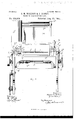
- Figure 1 is a4 plan view of a machine embodying the several improvements in the best form now known to us.
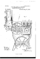
- Fig. 2 is a front elevation.
- -Fig. 3 is an elevation of the left hand side.
- Fig. 4 is an elevation of the right hand side.
- Fig. 5, is a longitudinal section on line 5, Fig. 1. Figs.
- ⁇ 6, '7 and 8 are transverse sections on lines 6,
- Fig. 9 is an enlarged detail in ⁇ section showing the construction ot' the pickers and accessory parts.
- Fig. l0 is a detail in elevation showing part of a gang of pickers.
- Figs. 10a, 10b and 10c are detail views of the pickers.
- Fig. 11, is a plan view of the lace-plate.
- Figs. 12 and 13 are sectional views on lines 12 and 13 re ⁇ spectively (Fig. 11).
- Figs. 14, 15 and 16 are' venlarged detail views illustrating the mowing mechanism and adjacent parts.
- the pickers are carried by slides or sleeves A, which are mounted and slide upon cross-bars A extending entirely across the machine. As seen in Fig. 9, there is app'air of cross-bars for each double row of pickers.
- Cross-bars' A have a vertical movenient derived from eccentrics b (Fig. 8) onthe main shaft, while the horizontal movement of the slides or sleeves A is derived from eccentrics on the ends of the main shaft encircled by the straps c (Figs.
- the cross-bars A are attached by bolts or screws to the upwardly projecting arms d of vertical slides D (Figs. 3 and 4) one on each side of the machine, which are at their lower ends attached to the horizontal rod d.
- the latter receives a vertical movement from the connection rod b actuated by eccentrics b.
- the slides D are guided and held in place by the upright bars or guide-blocks D (Fig. 8)v
- the picker-slides A are at their outer ends i attached by means of short links c (Fig. 8) to the vertical arms c2 of the rock shaft C, which is oscillate'd by the connection-rod c4 through a ball and socket connection, at the end of pin c3.
- Each gang of pickers is preferably carried by a holding plate E (Figs. 9 and l0) detachably secured to the slide A by screw-bolts e.
- the picker plate E has a small longitudinal tongue e', and in the shank of each picker is cut a corresponding groove.
- the end picker toward the center of the machine has two holes as into which iit corresponding pins projecting from the support or plate. This iixes the first picker in an upright position, and determines the positions of all the f others which are fitted upon tongue e and arranged vin close contact along the entire plate.
- a steel bar a4 is placed in the position which would be occupied by the last picker, which bar acts as a guard to the'toe or point of the picker adjacent to it.
- This bar has on its outer face a pin d5 which tits in a groove in one end of guard-plate or strip which is placed over the Shanks of the entire line of pickers, and held in position byclamps E2.
- the outer end of strip E is similarly supported by one of the pins which hold the end picker.
- an eccentric E3 having a milled surface for turning, is used to compress the entire line, and when this is done the posi tion of the eccentric and of all the pickers is fixed by means of alock-nutE4.
- This method of mounting the pickers is useful whether they are carried by a detachable holding plate, as shown, or attached directly to the bars or slides, as heretofore.
- the pickers are set closer together, permitting the use of a larger number than when a separate socket for each shank is formed in the picker-support.
- the mounting moreover is simple and efficient and admits of the ready removal of any individual picker, or of the entire gang, as occasion may require.
- a Asingle cross-bar A' between them and the front of the machine, which is similarly connected to and moved by the slides D.
- This single cross-bar carries the brushesf, which act upon the lace in advance of the pickers.
- the function of these brushes is primarily to loosen the picksA or floats, which as the lace is received for picking, are stuck to the groundwork of the fabric. y They also act to spread or stretch the lace laterally and thus prepare it for the action of the pickers.
- These brushes f (Figs. 5, 6 and 7) are carried by sleeves or slides, mounted on bar A and move in the same manner as the pickers themselves, that is, they brush from the center toward the sides of the machine.
- the brushes are arranged in a double row, and each row is composed of four separate gangs or sets (though the number maybe greater or less).
- Each gang or set is carried by a holding plate Ff, F2, dac., secured toits slide by bolts, so as to be adjustable vertically.
- the slides carrying the outer sets F', F4 are attached by short links f to the vertical arms fz of rock-shaft C, and the intermediate sets F2, F3 are attached by linksf3 to the same armsf2, but at points nearer to the axis of the rock-shaft C. Consequently the brushes at tlie sides of the machine have a larger movement than those near the middle, and the lace is thereby eectually brushed and spread over the entire surface.
- a vertically acting clamp f4 (Figs. 5 and 6) preferablyhavihg a strip of rubber let .into its lower edge.
- This clamp is carried by vertical pins f5, which are normally pressed downward by springs f6. When the pickers rise, however, the clamp is also lifted- IOO IIO
- roller F Between the two lines or rows of brushes is a roller F (Figs. 5 and 7) which rests upon the lace. In the periphery of this roller are cut ratchet-shaped grooves, the vertical faces of these grooves at each side being turned away from the center of the machine. Consequently, as the brushes rise after brushing and stretching the lace, the teeth of the roller engage the surface ef the lace and keep it extended.
- the lace plate is grooved transversely beneathl the roller, so as to extend the surface of contact between the latter and the lace.
- the journal pins (Fig. '7)
- rollers g are journaled in plates G4 (Fig. 5), recessed into Vthe'side walls of the machine and having a slight vertical play therein. These bars are supported by upright rods g3, having bearings in brackets G, and reciprocated through abell-crank g4 and connectionother there is little but the net or ground work, and in this case it is not desirable to employ spiral or spreading threads on that part of the rollers which act upon thev head,Y but simply to hold it against the drawing action of the spiral part of the roll. In other words, the particular rollers used must. be vadapted to the work to be done, the obqect being always to equalize the spreading action.
- rollers g workin grooves or depressions in the lace plate, so as to give the rollers a suiicieut surface in contact with the lace to act properly upon it.
- the throat plate over which the lace is bent while the rotating mower or cutter K removes the severed clips is asshown, composed of a plate or strip H (Fig. 14) set between two clamping jaws H', H2, held together by screws H3, the upper jaw H being attached to the throat plate holder I, by screws H4.
- the holder I rests normally on a ⁇ projection I of the frame.(Fig. 5) and is supported ateacli side by a slide I2 which tits in a slot in the frame, and is attached by a link t to an upright lever ⁇ I3.
- the lever I3 on the right-hand side of the machine (Fig. 4) has a handle I4, by which the throat-plate is drawn back during the insertionof'a piece ot lace into the machine.
- lace before reaching the throat-plate, passes between two rods m, m connected together at their ends by oblong plates fm2.
- Rod m is jonrnaled in holes m3 (Fig. 14) in the throatplate holder I, so that the whole device can turn on the axis of rod m.
- the setting-olf device is a transversely arranged lever Z (Figs. 1, 5 and 18)'pivoted at Z to the back of the holder I. The inner end of this lever lies just beneath the lace under rod m', but not necessa-rily in con tact therewith.
- the outer end of lever Z is just beneath a link or arm L (Figs. 17, 24 andv 25) pivoted at one end to the vertical releasing-lever M.
- a screw Z2 is interposed between the arm L and the lever Z, and screwed into the latter.
- a pivotedy arm N Vhangs vertically from the frame, resting at its lower end against a stop pin n, by which its movement in one direction is limited
- This arm carries an adjustable pin n against which rests a link c' carried by the pinj, which connects link t' with the throatplate holder I. Pin n therefore determines the proximity of the throat-plate H to the mower K.
- the movement of the arm N to the left (Fig. 17) will move the holder I and throat-plate in the same direction.
- This desired movement is derived from a cam O (Figs. 20 and 21) on a shaft O, which is the continuously rotating shaft of one of the feed rollers O2.
- the hub of cam O is loosely mounted on said shaft, but can slide thereon.
- abellcrank lever P Near the free end of the arm L is abellcrank lever P, which is constantly vibrated by means of a link P from the counterweight P2, (see Fig. 4,) or it may be from some other moving part.
- the vertical arm of lever P carries a pin catch 79, whose edge vibrates back and forth just above and clear of the hook L2 011 the end of arm L.
- theouter end Z2 liftsarm L a sufficient distance to brlng the hook L2 into the path o f catch p (as showny in Fig.'24).
- the setting-off lever acts a certain time'before the seam actually reaches the edge of the throat-plate, but the drawing back of the latter does not begin at once, for by reference to Fig. 17, it will be seen that the vshaft of feed-roller O2 turns through a considerable portion of a revolution before camy O begins to act on arm N.
- Fig. 25 shows the positions of the parts after cam O .has engaged and pushed back arm N to the full extent, and the throat plate being now open remains open, until the cam has passed projecting point of arm N, against which it bears, when through the action of spring 'Z2 (Fig. 18) the shaft t3 with its levers I3, throat plate holder, and all connected parts, are returned to their original positions.
- the cam O Since the actuating cam O derives its movement from the feed roll O2, it is only necessary-in order to time accurately the action of the drawback mechanism, that the cam O should be arrested, at a determined distance from the arm N, that is to say, about the disthe feed-rollers P5, P6 and finally passes over a roller P7 to a basket or receptacle placed to receive it.
- the arms Ps by which roller P7 is carried may be extended horizontally, so as to prevent silk lace being drawn by Velectrical action against the frame of the machine and all these rollers may be rotated in the proper direction by belts and pulleys as shown in Fig. 3.
- the lace plate Q (Figs. 5, 7, 1l, 12 and 13) is adjustably supported on cams Q', whose shafts are connected together by arms Q2 and link Q8 (Fig. 4), so that the lace plate can be lowered or adjusted as desired, substantially as described in our former patent, No. 361,563.
- the upper surface of the lace plate, upon which the lace rests when acted upon by the pickers, is formed Vby a series'of transverse strips or barsq adjustably and removably attached to the lace-plate by nuts q fitted intoYT-grooves in the top of the lace-plate, and holding screws q2.
- the effect ot' these strips is practically to make channels, grooves or depressions extending across the lace-plate in the direction in which the -lace travels.
- Such a groove, channel or depression ⁇ Q5 is shown in Figs.
- the guiding fingers (16 are attached to the lace plate in the same manner as the strips q and are'likewise adjustable.
- the removable throat-plate H (Figs. 14 and 16) has a row of perforations h through which air is drawn into the exhaust duct or pipe. The vcurrents of air passing through these holes assist in lifting the iloats, and causing them to stand out properly for the action of the mower.
- the plate H also has an indented or cut-away portion 7L (Fig.16) and that part of the lace which comes opposite this cutaway portion of the plate will be held farther away from the cutter than the surface of the rest of the lace. This indentation is intended to accommodate the thick pattern of the lace, and of course, its position and width must be varied with the different kinds of lace. On this account the ability to quickly remove and change the throat plate is a matter of importance.
- a guard shown in the form of a section of a comb h3, whose teeth vextend to a point opposite the indentation in thethroat-plate, and effectually hold that portion of the lace out of the way of the cutter blades.
- the width of the comb, or guard used with any pattern of lace will correspond with that of the indentations in the th-roatplate, and if there be more than one such indentation there must be several comb-sections or guards, properly placed.
- the comb-slide h4 is removably and adjustably mounted on a bar h5 extending across the machine, and secured thereto by a screw h6 and nut hl, the latter sliding ina T-groove in the bar h5 (Fig. 14).
- adjustable gages just above the opening through which the lace passes into the machine.
- One of these gages R is shown in Figs. 2 and 5. It is adapted, by means of a screw and nut, to slide in a T-groove r, of a bar R', which extends across the front of the machine. The lower surface of the bar is rounded and extends into a groove in the lace plate beneath it, so as to be slightly below the upper surface of said plate, and thus exclude air at this point, so far as possible.
Landscapes
- Engineering & Computer Science (AREA)
- Textile Engineering (AREA)
- Braiding, Manufacturing Of Bobbin-Net Or Lace, And Manufacturing Of Nets By Knotting (AREA)
Description
(No Model.) 11 Sheets-Sheet 1.
C. H.y WILLCOX :8v J. RANGE. MACHINE FOR GLIPPING LAGE.
No. 524,924. Patented Aug. 21, 1894.
(No Model.) 11 sheetssheet 2. G. H.. WILLCOX 8v J. RMVGE.V
MACHINE POR GLIPPING LAGE.
No. 524,924. Patented Aug. 21,` 1894.`
(No Model.) 11 Sheets-Sheet 3.
C. H. WILLOOX 8v J. RANGE. MACHINE FORGLIPPING LAGE.
No. 524,924. Patented Aug. 2l, 1894.
mu-M
(No Model.) 11 Sheets- Sheet 4. C. H. WILLCOX & J. RANGE. MACHINE PoR GLIPPING LAGE.
Ptented Aug. 21, 1894.
ne nofws PETERS 00,. PHOTO-urna.. wAsr-xmcrron o f g, 5 A.\ me@ 9 m w @www l ,2 Mm a.. 04./ n @w Wwf nB M wv/WW1* www AAt Bmw .NM x @MH VXM 0R C0 LP.. WH -M HM nw l Am 2 9 U 4 m w m o. m N
(No Model.) 1i sheets-sheet 6.
C. H. WILLGOX auf J. RANGE. MACHINE POR GLIPPING LAGE.
No. 524,924. Patented Aug. 21.1894.
sf 1. 5N
.C4 v Q. l m D 2 .\vll/1111,11111/1/11111/11111a/1 '1 'mi nonms Urns co. wormlwc.. wnsmutn'on. mc. l
L 3 Q @C34 l1 3 w 8 IE 3 t h 1|- 1 2 l @1a e 8 n A] m g b 1 u o 1B e\|\ Gun.. d S f3 e NG B AH 9 AA b Ja RL n L nu S I9 2 e S, T A uG ITU E Tum a 6 P. D.. e Q. um wA XG .ma Q OR s N z e T. L S l LM E 4 m1 s m I E a 9 HA mw M cl/ C. o m o b 9 -a @nu M AM. AC D 2 C 0 5 .D m 0. Q @+V s m N D u, c
8. t e e n s M e e h s uw. Nm M L G .dm D.. oww Xu 0R kC0 LF.. LB 1m WH .M AHM 0. m. d 0 M o m No. 524,924. Patented Aug. 21, 1894.
Lm@ J- c w. www. 2..
we wams Ptrzns ou. wom-uma.. WASHING-runV D. c.
(No Model.) 11 Sheets-Sheet 10.
C. H. WILLCOX '8a' J. RANGE. MACHINE PORGLIPPING LAGE.
No. 524,924. Patented Au?. 21, 1894.
n 1. l. t 9 my w M 1l e S 2 m l h g l ao mv S uw u I l l O Il.l m HH-...M` IN1 mu O MM/ m Rd M GG W ,.NM JH?` oww L A5 w XU. Z m OR n.0 M C0 m LP /M m LE f mm H C .A HM C.
(No Mudel.)
No. 524,924.i
- said invention comprises certain improve.
NITED STATE-s `lAIEINrI`V OFFICE.
CHARLES I-I. wiLLoox, OE NEw YORK, N. Y., AND JAMES' RANGE, OE NOT- TINE-HAM, ENGLAND, AssIeNoRs To4 THE wILLCox a GIRRS SEWING MACHINE COMPANY, O ENEW YORK, N. Y.
MACHINE FOR CLIPPlNc LACE.
SPECIFICATION forming part of Letters Patent No. 524,924, dated August 21, 1894. Application i'lled February 1, 1893. Serial No. 480,577. (olmodel.) `Ilatented in England December 24, 1892, No. 23,846.
To @ZZ whom it may concern,.-
Be it known vthat we, CHARLES H. WILLoox, of New York city, in the county and State of New York, and JAMES RANGE, of Notting- Aham, England, haveinvented a new and usetul Improvement in Machines for Clipping- Lace, which improvement is fully set forth in the following specification, and for which British Patent No. 23,846, dated December 24, 1892, has been obtain-ed.
This invention has reference to machines for clipping lace of the same general character as described in United States Letters Patent No. 353,615, dated November 30, 1886, and No. 361,563, dated April 19, 1887; and the ments in machines of this class, which `improvements, together with the Objects thereof, will be fully described herein.
First. Heretofore the pickers were carried` upon bars which overhang the lace-plate, and extend half-way across the same, meeting. similar picker-carryingbars extending from the opposite side. This construction is suitable, and even preferable for machines of comparatively small width, but is inapplicable to machines designed to act upon very wide pieces of lace, owing to the springiness of the bars, which if extended in length beyond a reasonable point, would at high speeds develop a tendency to whip and cause variations in the stroke of the pickers. By means of the present invention,lace clipping machines of any desired width can be con-` structed and to this end the pickers are' carried upon slides or sleeves, mounted upon a bar or bars, bridging the entire width of the machine, and` of sufficient strengthfor the purpose in view. These bars in turn rest upon slides which work in guides fitted to the frame of the machine at each side, these guides being given a vertical movement by means of suitable connecting rods and eccentrics, or other actuating devices. The horizontal sleeves or,slides.(of which there are two for -each two lines ofepickers) extend half-way across the machineand meet almost at the center. They are given the necessary reciprocating movements toward and away y with eccentrics on the main-shaft.
`of the machine.
from each other by means of suitable actu- 5o ating devices such'asbell cranks connected The pickers may beattached directly to the sleeves or slides, or they may be clamped to detachable plates, which are in turn secured to the sleeves or slides. The latter arrangement is preferred.
, Second. -In order to assist in` keeping the lace stretched out to its greatest width and at the samejtime loosen the oats or clips 6o from the bodyof the net preparatory to their being picked up and cut by the cutting pickers, brushes are provided which are given the same movement as the pickers; that is, they brush from the center outward toward the edges of the lace. In the construction for thewide machine, these brushes are clamped to and carried by sleeves, the same as the pickers; but in the narrow machine, they may be carried by bars in the same manner 7o as the pickers are carried.
Third. Just inside of the cover and before the lace arrives at the brushes, it passes under a vertically acting clamp (preferably having a strip of rubber inserted in its lower edge) which clamp during ,the operation of the brushes presses by spring pressure upon 'the lace, but is caused to rise automatically and release the lace when the time comes for feeding the lace into the machine.
Fourth. Between the two `lines of brushes a roller is placed, having in its circumference ratchet shaped grooves, i. c. grooves which are vertical on one side and inclined on the other. The vertical. faces of these grooves are at each side turned away fromthe center The roller is journaled in vertical grooves in the side walls of the ma# Achine and rests in action upon the lace, which the vertical face of the threads being toward the outside of the machine at either side. These rollers are given a, constant rotary movement by suitable connection with the main shaft, and turn in such direction that.
the under side of the rollers moves in an opposite direction to the feeding of the lace through the machine; and the screw threads are cut in such direction that they tend to spread the lace as they turn in contact with it,and as the lace is fed through the machine, These rollers are sometimes made with the screw only on one side of the center, being cut on the other side with ratchet grooves encircling the rollers at right angles to their axes. In this case such portions of the rollers only act to keepjthelace extended at that side of the center of the lace-plate. This construction is desirable when'the machine is acting upon lace ou the edges of which is a head composed of heavy threads, forming the pattern while at the otherv edge of the lace there is little but the net or ground work of the lace. It is desirable in this case only to spread this edge of the lace, while allowing the head of the lace to pass through the machine without action by the rolls except to hold against the spreading action of the spiral portion of the roll. In some cases also the ratchet thread may be on both sides of the center,but on one side it will bea single threaded screw, while on the other a double threaded screw. These various combinations can be made by merely changing the rollers as required. These rollers act in grooves, or their equivalents, cross-wise of the lace-plate of the machine, the lace always passing in a bent or corrugated form through the machine so Aas to give the rolls an opportunity to spread or hold the lace. As before stated, some orall of these rollers may be simultaneously moved in guides or bearings, having a vertical movement opposite to that of the pickers, so that when the pickers are up and clear of the lace, the rollers will be depressed still further into the grooves in the lace-plate, while when the pickers are depressed on the lace, the rolls will occupy relatively a` higher position. The effect of this movement ot the rollers is alternately to draw more lace through the machine and'then give it up again as the` pickers descend upon it, which in the case of delicate lacerelieves it from undue strain caused by the pickers depressing it into the picker grooves in the lace-plate. Y
Sixth. The lace in its further passageY through the machine passes through a device which is intended to give sufficient tension Vedge of the throat-plate.
on the lace and cause it to bend sharply over the edgeof the throat plate, so as to present the split ends of the clips or floats in proper position to be moved oft by the rotary cutter. This tension device preferably consists of a roller of proper weight, turning in vertical grooves in the side walls of the machine, and pressing the lace between itself and any stationary part ot the machine-such as the laceplate itself-but any usual or suitable construction t'or imparting friction or tension could be used. This tension, as it will be seen, is placed after the pickers have completed their work upon the lace and before it reaches the mowing mechanism, as at this time, whatever tension is necessary to produce perfect mowing can beapplied to the lace without in terfering with the proper action of the pickers, which demand a lighter tension upon the lace as it passes under them.
Seventh. It is desirable in passing lace through the machine that it should be first ,sewed together into continuous strips of sufficient lengthl to avoid stopping .the machine' 'frequently to insert new pieces of lace, and
through freely, it will, because of the extra thickness at the seam, be cut off by the mowing mechanism, and the strips separated. To overcome this dittlculty, an automatic set-tin gol device is introduced into the machine, by which, as the lace passes between a station- .ary portion of the machine andI al delicate lever, which always rests upon it, the addiltional thickness of the fabric sets in action Lproper mechanism to move the throat-plate away from the mowing mechanism and to return it as soon as the seam has passed the While the settingo device is necessarily delicate in its operation, it brings into act-ion moving parts of the mechanism, which act with all necessary power to produce the movement of the throatplate with certainty and at the proper time.
Eighth. The lace, after being mowed passes `downward and under the block in which'the vrotary-cutter is journaled and thence under a roller and upward in front of a display-plate of card-board or sheet metal, leither white or colored, as best adapted to allow the pattern of the lace to be seen by the operator. The lace is caused tol move in this upward direction by suitable means, such as a moving roller, upon which a weighted roller presses; and thence it is or may bepassed over auother roller supported on arms extending from the back of the machine;l all the rollers being given larotary movement in the right direction by suitable belting from the moving parts of the machine. The lace, after passing the nal roller, falls into a basket or other receptacle. This last roller is extended IOO IIO
IIS
some distance from the back of the machine in order to give room for a basket to be placed there, and also to prevent silk lace being drawn by electrical action against the frame of the machine. j
Ninth. Lace, as commonly made, has a back or selvage on either or bothedges. This selvage or back is composed of straight threads, which are generally heavier than the thread from which the net is made. The net threads pass around the backthreads and unite them to the body of the net In order to prevent this back or selvage being picked up andcut by the eutting pickers, it has been found necessary to support the lace upon a surface or surfaces of. less width than the width ofthe lace, and raised above the general surface of the laceplate, so as to allow the two edges of thelaee to be depressed below this raised surface by means of the rotating grooved rollers or their equivalent. Wherever the stri pofrlace toi be clipped consists of two or more breadths of lace united by the draw threads, these raised surfaces must ,be of the right width and in the right position to, support each breadth of lace within the salvege or scalloped edge line. This, in effect, will form grooves or depressions in the lace-plate, lengthwise of the lace, the middle ot each groove 'being in line with the back or selvage of each breadth of lace. These raised surfaces may be formed in various ways. Preferably they are formed by using strips of varying lengths, adjustably attached to the upper surface of the lace-plate, which, in case the lace is wide enough to almost tit the machine, are long enough to be nearly the width of the lace, or in case several strips of lace, still united `by their draw-threads arebeing passed through the machine, then these adjustable strips will be of the proper length for each breadth of lace, but always less than the width ofthe lace. Consequently a space or spaces will be left between the ends of these strips into which the backs or selvages are depressed by the ratchet rollers or their equivalent, before referred to, and are kept clear of the action of the pickers. It is seldom that the p'attern on the lace extends quite to the selvage edge, consequently it is only necessary to have the adjustable strips hold the lace up to be acted upon by the pickers, where there are clips or floats to be removed. These adjustable strips are used on both sides of the lines of pickers, and thus form the grooves into which the lace is depressed by the pickers in picking and cutting the iioats orclips. InV practice these raised surfaces areipreferably secured to the upper plane surface of the laceplate by a tongue on the under side of the strip entering a groove in the,r laceplate,
through which screws enter nuts sliding inV T-grooves extending across the vplate under each line of strips. By this means these adjustable strips may be accurately adjusted and readily changedas required. Each of be mowed olif by-the rotary cutter.
these adjustable strips is preferably rounded on one edge and forms the surface over which the lace is depressed by the spreading rollers or `their equivalent. By substituting laceplates, in which the grooves for adjustable strips vary in distance from the center of the picker slots or grooves, any desired distance between the edges of the strips adjacent to the pickers (in other words picker-grooves of any desired width) can be secured, while still using the same adjustable strips. In praetice it is found desirable to have these plates, giving various widths of picker grooves, to
accommodate different styles and designs otv lace.
Tenth. In order to continue the spreading action of the spiral ratchet rollers to the extreme edge of the outside salvage or selvages, some of these adjustable strips are made sufficiently long to allow the selvage edge torest clear to the edge of the lace on the adjustable strips, but they are cut away'on a bevel toward the edge forming the picker grooves, so fas to allow the back or selvage to be depressed below the general upper surface of the strips by means of overhanging guides or fingers. These guides or fingers extend inward and over the bevel of the adjustable strips and the under surface of the projecting part of the guides or fingers is a' little below the general upper surface of the strips. They approach as closely as may be to the shoulder or corner formed by the bevel and still permit, the lace to pass freely. As these lingers are or may be adjustably secured to the lace-plate in the same manner as the adjustable strips and are or may be on both sidesof the lines of pickers, it follows that the selvage edge or back p is held safely below the action of the pickers and still the spreading action of the ratchet rolls is secured to the extreme edge of the lace. These depressing guides or lingers can be used on either or both edges of the stri ps of lace.
Eleventh. The throat-plate or the plate over `which'the lace is bent in order to throw out jects far enough beyond the point whereit is clamped toits support to allow holes to be drilled or punched through it close to the edge over which the lace is being drawn.
These holes allow air to be drawn throughV the lace by means of the air exhauster, which is connected to the machine for the purpose of removing the severed clips.` The air so passing through the lace tends to lift up the severed ends of the clips or ioats as they approach the edge of the throat plate and assist in presenting them in proper position to In order to compel the air to pass through the perforated plate strip and also to produce the suction through the lace-plate, as provided in IOO our former patent (No. 861,563), the machine is made as nearly air`tight as possible except at the points where it is arranged for the air to enter. j
Twelfth. As the pattern or ligure upon lace is often very much heavier than the general thickness of the net from which the body of the lace is formed, it follows thatin passing the lace over a straight throat-plate, the thick portion comes too near to the cutter before the thinner portions of the lace approach near enough to allow the ends of clips being mowed closely to the fabric. To compensate for this condition we cut away the edge of the throat-plate strip, where the thick portion of the lace comes, sufficiently to allow that part of the lace to be held farther from the rotary cutter than it otherwise would be. The amount and position of this cutting away of course'varies in dierent kinds and patterns of lace, so that ability to quickly andcheaply change the edge of the throat-plate by the use of sheet-metal strips is of much importance.
Thirteenth. In order to insure the protection of the thick portion or pattern of the lace, j
we have combined with the throat-plate, a guard, which is preferably in the form of a section of a comb, and we may employ one or more such guards, according to the requirements of different patterns of lace. We make the combs in sections of different lengths and l adjustably secure them to the comb-bar in any desired position by means of a screw and nut working in a T-groove in the comb-bar.
By placing a comb of the proper width opposite the portion of lace requiring protection and opposite the cutaway portion ofthe throatplate strip, as provided above, when that is used, the safety of the lace is assured at this point, and the rest of the lace not requiring the comb, willv be more perfectly cleared. In place of the comb a solid shield of the same section as the comb may be substituted, where the part of the lace sought to be protected has no clips.
Fourteenth. At the point where the pickers bear against the stationary blades, which cooperate with the pickers in severing the clips or Iioats, it'is necessary that asmall quantity of oil be provided, and it is desirable that this be done in such manner as to insure its being constantly supplied in about the right quantity. To accomplish this, we form oneI or more reservoirs in the upper part of the bridge to which the stationary picker blades plied in theoretically the best place for doing the work and there is no surplus oil to soil the lace, as all that is notl required to lubricate the pickers is carried away by the severed The oilis thus sup-y clips in their passage out of the machine to the exhauster.
Fifteenth. In order to adjust and secure the pickers to the detachable plates (when these are used) or to the picker-carrying bars themselves, as used in the arrangement for narrow machines, we fornr the picker-supports (whether plates or bars) with a tongue projecting from a flat surface, andL cut into the side of the picker shank a groove to correspond. The pickers at the end of the bar or support toward the center of the machine are made with two holes through the shank, and the supports are made with pins, which enter these holes in the endv pickers. This gives the end icker an upright position and at the same t me allows the next and succeeding pickers to be pushed up against it along the tongue. When the bar or plate is tilled with pickers along its entire length, instead of terminating the line with a regular picker, a piece of steel of the same width and thickness as a picker is used, which instead of having its lower end cut into the lform of a picker is rounded on its lower edge toward the side wall of the machine, the other corner beingleft square. This protects the point or toe of the picker adjacent to it, and prevents it from entering the net or fabric of the lace, serving the same purpose as the heel of the adjacent picker does to the point of the one nearest to it, and so on through the line of pickers. An eccentric or other suitable device is then used to compress the picker Shanks together along the tongue until they form a solid mass at the shank. f A4 plate or strip suitably supported is then placed over the shanks of the pickers and clamps are swung over it, which clamp the pickers against the liat face of the picker carrier, or support. The toe of the pickers being narrower than the shank, it follows that a space is left between `the toe of each picker and the heel of the succeeding one in order to allow the iioats or clips to rise between and be picked up and severed by the pickers. This arrangement allows of pickers of various widths, thickness and heights of toe to be used on the same picker carrying bars or plates and sesition.
Sixteenth. In former machines the acting end of the picker described, in its movement,
'an oval or ellipse, whose major axis was par- IOO cures them in an accurate and substantial pojor axis of the ellipse on each side of the center of lace-plate is oblique to the lace-plate, and inclinesdownward toward the middle of the lace-plate. The object of this arrangement is to cause the pickers, as they move backward and downward, to act with greater certainty upon the floats or clips, which lpass between the toes and heels of adjacent pickers j and are caught upon the former.. The motion of the pickers downward, to engage the floats or clips, is by this arrangement, more nearly vertical than heretofore, and consequently surer to effect the desired object.
Seventeenth. Instead of giving the upper surface of the toe of the picker an angle rising toward the cutting edge, as provided in our former patent, No. 361,563, we make this surface parallel in a transversedirection to the lower side or end of -the picker. This makes the toe or nose of the `=picker parallel across its whole width, and allows the end to beV nicely rounded in all directions toward the upper or cutting surfaces. Instead of twistlng the toe of the picker so as to make the cutting edge approach the stationary blade nearer than at the heel, as provided in our prevlous patent, No. 361,563, we grind or lap the cutting side of the picker ata slight angle, not only to a vertical line but to a hori zontal line through the center of the line of pickers. This makes the end of the picker' narrower at the heel than at the toe andhas the same eect, so` far as the cutting edge is concerned, as twisting the picker, butV is Aan improvement upon it,`since it leaves the other side of the picker parallel to the grooves in the lace-plate.
Eighteenth. It being necessary to guide the laceN accurately through the machine so as to have the selvage edges or the backs pass through the centers of the grooves ordepressronsmade by the adjustable strips, we prov1deadjustable gages under which the lace passes as it entersthe machine. Preferably we attach these gages by means of screws and nuts entering` a T-groove cut in the face of the bar which is laid in grooves cut in the side walls of the machine. `Theupper surface of this bar is squ`are and the cover when` closed lits against it. The .lower end of the bar is rounded and comes about even with the upper surface of the lace plate, and in order to allow lthe lace Vto pass freely, a rounded groove is cut in the lace plate under the bar. The gage points are bent partly around the front curved surface ofl the bar so as to approach thelace as nearly as possible. By this arrangement, while the lacepasses freely into the machine, but little air passes in with it and the gage points are close to the lace. n
Nineteenth. The clips or floats which have been severed by the cutting pickers as the lace passes under the'gang of pickers are not only cut in two, but before they pass beyond toward the rear of the machine naturally have a tendency as the lace is fed through the machine to push through between the pickers and upward against the inclined surface of the stationary knife bridges, where they remain after being severed from the lace, and partly by the action of the exhauster causing a current from the front to the rear of the machine which draws the severed portions of the clips with it, and in some cases leaves `them behind they pickers. When `the machine has been running a while it is necessary to. stop it and with a pair of tweezers remove these severed clips which are packed in behind the rows of pickers. To obviate this difliculty we make the 'picker carrying bars or slides ofsuch form that a current of air is drawn by the action of the exhauster from the Outside of the machine between the stationary blade bridges and the rows of pickers, coming out j,
`side of the bridges, the bridges and pickercarrying bars or sleeves are so formed that the current of air brought in through them is directed only toward the front rows of pickers. This at the same time prevents the current of air through the machine before referred to from passing betweenthe pickers and compels all the air which enters the machine through the lace-plate from below, or the air brought in through the picker carrying bars or slides, from above, to pass upward and over the picker carrying bars or slides to the exit at the rear of the machine. j
In the accompanying drawings which form part of the specification, Figure 1, is a4 plan view of a machine embodying the several improvements in the best form now known to us. Fig. 2, is a front elevation. -Fig. 3, is an elevation of the left hand side. Fig. 4, is an elevation of the right hand side. Fig. 5, is a longitudinal section on line 5, Fig. 1. Figs.
` 6, '7 and 8 are transverse sections on lines 6,
'fand 8 (Fig. 5) respectively. Fig. 9, is an enlarged detail in `section showing the construction ot' the pickers and accessory parts. Fig. l0 is a detail in elevation showing part of a gang of pickers. Figs. 10a, 10b and 10c are detail views of the pickers. Fig. 11, is a plan view of the lace-plate. Figs. 12 and 13 are sectional views on lines 12 and 13 re` spectively (Fig. 11). Figs. 14, 15 and 16 are' venlarged detail views illustrating the mowing mechanism and adjacent parts. Figs. 17, 18,
IOO
viewvshowingvpart of one of the toothed spreading rollers. y
In the machine shown in the drawings there are two double rows of pickers a (Fig. eX-
tending practically across the entire machine, but each divided near the middle line of the machine into two sets, working in opposite directions, as in 4Letters-Patent No. 361,563, above referred to. The pickers are carried by slides or sleeves A, which are mounted and slide upon cross-bars A extending entirely across the machine. As seen in Fig. 9, there is app'air of cross-bars for each double row of pickers. Cross-bars' A have a vertical movenient derived from eccentrics b (Fig. 8) onthe main shaft, while the horizontal movement of the slides or sleeves A is derived from eccentrics on the ends of the main shaft encircled by the straps c (Figs. 6, 7 and 8).V Consequently the pickers a move in an elliptical path which is the resultant of these two movements, and as already explained the eccentrics are so placed relatively to each other that the major axis of the ellipse is inclined downwardly toward the middle of the laceplate (Fig. 10a);
p The cross-bars A are attached by bolts or screws to the upwardly projecting arms d of vertical slides D (Figs. 3 and 4) one on each side of the machine, which are at their lower ends attached to the horizontal rod d. The latter receives a vertical movement from the connection rod b actuated by eccentrics b. The slides D are guided and held in place by the upright bars or guide-blocks D (Fig. 8)v
rigidly attached to a portion of the frame of the riiachine. The slides are held upon these blocks by lateral flanges d2 and gibs d3 overlapping the faces of the blocks as shown in Fig. l.
The picker-slides A are at their outer ends i attached by means of short links c (Fig. 8) to the vertical arms c2 of the rock shaft C, which is oscillate'd by the connection-rod c4 through a ball and socket connection, at the end of pin c3.
Any suitable means for imparting the proper movements to the supporting-bars and picker-slides may be employed in place of those described.
Each gang of pickers is preferably carried by a holding plate E (Figs. 9 and l0) detachably secured to the slide A by screw-bolts e. The picker plate E has a small longitudinal tongue e', and in the shank of each picker is cut a corresponding groove.
In assembling a gang of pickers, the end picker toward the center of the machine (Fig. 10) has two holes as into which iit corresponding pins projecting from the support or plate. This iixes the first picker in an upright position, and determines the positions of all the f others which are fitted upon tongue e and arranged vin close contact along the entire plate. When the holding plate is thus filled with pickers, a steel bar a4 is placed in the position which would be occupied by the last picker, which bar acts as a guard to the'toe or point of the picker adjacent to it. This bar has on its outer face a pin d5 which tits in a groove in one end of guard-plate or strip which is placed over the Shanks of the entire line of pickers, and held in position byclamps E2. The outer end of strip E is similarly supported by one of the pins which hold the end picker.
When the pickers are set in place along the tongue e', an eccentric E3, having a milled surface for turning, is used to compress the entire line, and when this is done the posi tion of the eccentric and of all the pickers is fixed by means of alock-nutE4. This method of mounting the pickers is useful whether they are carried by a detachable holding plate, as shown, or attached directly to the bars or slides, as heretofore. The pickers are set closer together, permitting the use of a larger number than when a separate socket for each shank is formed in the picker-support. The mounting moreover is simple and efficient and admits of the ready removal of any individual picker, or of the entire gang, as occasion may require. p
As shown in Figs. 1 and 5 there is, in addition to the two pairs of picker-supporting cross-bars, a Asingle cross-bar A', between them and the front of the machine, which is similarly connected to and moved by the slides D. This single cross-bar carries the brushesf, which act upon the lace in advance of the pickers. The function of these brushes is primarily to loosen the picksA or floats, which as the lace is received for picking, are stuck to the groundwork of the fabric. y They also act to spread or stretch the lace laterally and thus prepare it for the action of the pickers. These brushes f (Figs. 5, 6 and 7) are carried by sleeves or slides, mounted on bar A and move in the same manner as the pickers themselves, that is, they brush from the center toward the sides of the machine.
The brushes are arranged in a double row, and each row is composed of four separate gangs or sets (though the number maybe greater or less). Each gang or set is carried by a holding plate Ff, F2, dac., secured toits slide by bolts, so as to be adjustable vertically. The slides carrying the outer sets F', F4 are attached by short links f to the vertical arms fz of rock-shaft C, and the intermediate sets F2, F3 are attached by linksf3 to the same armsf2, but at points nearer to the axis of the rock-shaft C. Consequently the brushes at tlie sides of the machine have a larger movement than those near the middle, and the lace is thereby eectually brushed and spread over the entire surface.
Just inside the cover and in front of the brushes is a vertically acting clamp f4 (Figs. 5 and 6) preferablyhavihg a strip of rubber let .into its lower edge. This clamp is carried by vertical pins f5, which are normally pressed downward by springs f6. When the pickers rise, however, the clamp is also lifted- IOO IIO
by arms f7 carried by slide D,nwhich come inV contact with the lower ends of pins f5. The function of this clamp is to assist in holding the lace while acted upon by the brushes,` so
as to prevent the lace from being pulled by the brushes to one side or the other of the proper lineot` feed.
Between the two lines or rows of brushes is a roller F (Figs. 5 and 7) which rests upon the lace. In the periphery of this roller are cut ratchet-shaped grooves, the vertical faces of these grooves at each side being turned away from the center of the machine. Consequently, as the brushes rise after brushing and stretching the lace, the teeth of the roller engage the surface ef the lace and keep it extended.
As shown in Fig. 5,the lace plate is grooved transversely beneathl the roller, so as to extend the surface of contact between the latter and the lace. The journal pins (Fig. '7)
` of this roller are guided vertically in slots fi lowered, toinsertlaceinto the machine, the
roller remains suspended. i
In its continued progress through the ma chine the. lace passes underaseries ot rollers g (Figs. 1, 5 `and 8) tive of .which are employed in the machine illustrated in the drawings. These rollers are cut on one`orboth sides of the center with spiral threads forming grooves whose vertical faces are turned away from `the centertoward the outside of the machine. Their function is to continue the spreadingaction upon the lace during the whole time it isbeing acted upon by the pickers. These rollers are rotated positively in such direction that the under surface in coutact with the lace moves'in the opposite direction to the travel of the latter. n This movement is derived from a pulley G (Figs. 1. 3 and 6) on the shaft of one ot' the rollers. This shaft also carries a sprocket-wheel g (Fig. 6) which transmits motion by a drive chain g2 (Fig. 1) to the next of the series of rollers, and by similar gearing the motion is transmitted to the entire series. In some cases it is desirable to give these rollers a slight vertical movement opposite to that of the pickers, so that when the latter descend the rollers will rise, and vice versa, thus alternately drawing more lace through the machine and giving it up as the pickers descend upon it, after the inan ner. of thetake-up rollers described in our former patent, No. 361,563. This action relieves the lace of undue strain` caused bythe pickers depressing it into the grooves of the lace-plate. To this end the threeintermediate rollers g are journaled in plates G4 (Fig. 5), recessed into Vthe'side walls of the machine and having a slight vertical play therein. These bars are supported by upright rods g3, having bearings in brackets G, and reciprocated through abell-crank g4 and connectionother there is little but the net or ground work, and in this case it is not desirable to employ spiral or spreading threads on that part of the rollers which act upon thev head,Y but simply to hold it against the drawing action of the spiral part of the roll. In other words, the particular rollers used must. be vadapted to the work to be done, the obqect being always to equalize the spreading action.
The rollers g, as shown, workin grooves or depressions in the lace plate, so as to give the rollers a suiicieut surface in contact with the lace to act properly upon it. Y
It is found desirable to arrange a tension device to act upon the lace between the picker mechanism and the mowing mechanisin,so as to cause the lace to bendA sharply over the ,proper weight. The `journal pins G3 of this tension roller (Fig. l) turn in vertical grooves in the side walls of the machine. The application of a tension device between the pick- Y ers andinowing mechanism is important for theieason already pointed out.
The throat plate over which the lace is bent while the rotating mower or cutter K removes the severed clips is asshown, composed ofa plate or strip H (Fig. 14) set between two clamping jaws H', H2, held together by screws H3, the upper jaw H being attached to the throat plate holder I, by screws H4. The holder I rests normally on a `projection I of the frame.(Fig. 5) and is supported ateacli side by a slide I2 which tits in a slot in the frame, and is attached by a link t to an upright lever` I3. i
The lever I3 on the right-hand side of the machine (Fig. 4) has a handle I4, by which the throat-plate is drawn back during the insertionof'a piece ot lace into the machine.
17, that is, so that the throat-plate occupies its forward position.
. When one of the seams bywhich the pieces of lace are held together passes over the edge of the throat-plate H,\it is necessary that the ICO ' approaches the edge of the throat-plate.
Referring to Fig. 5, it will be seen that the lace, before reaching the throat-plate, passes between two rods m, m connected together at their ends by oblong plates fm2. Rod m is jonrnaled in holes m3 (Fig. 14) in the throatplate holder I, so that the whole device can turn on the axis of rod m. The setting-olf device is a transversely arranged lever Z (Figs. 1, 5 and 18)'pivoted at Z to the back of the holder I. The inner end of this lever lies just beneath the lace under rod m', but not necessa-rily in con tact therewith. The outer end of lever Z is just beneath a link or arm L (Figs. 17, 24 andv 25) pivoted at one end to the vertical releasing-lever M.
A screw Z2 is interposed between the arm L and the lever Z, and screwed into the latter. By means of this screw the proximity of the inner end of lever Z to the lace passing above it can be regulated to a nicety. j
A pivotedy arm N Vhangs vertically from the frame, resting at its lower end against a stop pin n, by which its movement in one direction is limited This arm carries an adjustable pin n against which rests a link c' carried by the pinj, which connects link t' with the throatplate holder I. Pin n therefore determines the proximity of the throat-plate H to the mower K. Obviously, the movement of the arm N to the left (Fig. 17) will move the holder I and throat-plate in the same direction. This desired movement is derived from a cam O (Figs. 20 and 21) on a shaft O, which is the continuously rotating shaft of one of the feed rollers O2. The hub of cam O is loosely mounted on said shaft, but can slide thereon. It carries a disk O3 having on one face a projecting pin o adjacent to which is a disk 04,' having a series of holes o', disk O4 bei ng pinned on and turning with the shaft. These two disks'constitute a clutch. Cam O is constantly pressed in a direction to bring the two members oftheclutch together by means ofaspring O5, but such engagement is normally prevented by the end of the release-lever M, which is pressed by spring M into the groove, formed between disk O3, and the edge of a disengaging cam O6.
Near the free end of the arm L is abellcrank lever P, which is constantly vibrated by means of a link P from the counterweight P2, (see Fig. 4,) or it may be from some other moving part.
The vertical arm of lever P carries a pin catch 79, whose edge vibrates back and forth just above and clear of the hook L2 011 the end of arm L. When a seam or joint of two pieces of lace passes over the inner end of the setting-oi lever Z, depressing it slightly, theouter end Z2 liftsarm L a sufficient distance to brlng the hook L2 into the path o f catch p (as showny in Fig.'24).
This instantly sets off the drawback mechanism for the throat-plate, since the vibration of lever P actuates release-lever M through' arm L` freeing the sleeve which carries cam O, and permitting spring 05 to move the sleeve withv its cam and clutch-disk to the left (Fig. 18) until pin 0 enters one of the holes 0', and all the parts connected with disk O3 begin to revolve, and continue to revolve for one full revolution of lfeed roll O2. When release-lever M returns at the next vibration of lever P, its end strikes and is arrested by the edge of cam O6, which has now moved under it.
The setting-off lever acts a certain time'before the seam actually reaches the edge of the throat-plate, but the drawing back of the latter does not begin at once, for by reference to Fig. 17, it will be seen that the vshaft of feed-roller O2 turns through a considerable portion of a revolution before camy O begins to act on arm N.
Fig. 25 shows the positions of the parts after cam O .has engaged and pushed back arm N to the full extent, and the throat plate being now open remains open, until the cam has passed projecting point of arm N, against which it bears, when through the action of spring 'Z2 (Fig. 18) the shaft t3 with its levers I3, throat plate holder, and all connected parts, are returned to their original positions.
As the actuating cam continues to revolve with the feed-roller and its shaft, provision must be made to disengage and arrest it at the completion of one revolution. This is effected mainly by the action of the disengaging cam O6. This extends only part way around the sleeve or hub, permitting the end of release-lever M to fall into its groove. It will be understood, of course, that the hook L becomes disengaged and returns to its first position so soon as the seam has passed the inner end of the setting-off lever Z.
When camOhas passed armNand allowed the throat plate to return, the oblique side 07 of cam O6 (Fig. 20) makes contact with the edge of lrelease-lever M and by the continued revolution of the cam this contact of the said oblique side with lever M, causes the sleeve to slide to the right so far as to withdraw the pin o from the hole in disk O4 in which it engaged. This movement has brought the notch O8 in the edge of disk O3 to the wedge shaped end of spring O9 (Fig. 17) which gives the ,final movement to disk O3 so as to clear the pin 0 entirely from contact with the face of disk O4, and to arrest the cam-sleeve just at the completion of one movement.
Since the actuating cam O derives its movement from the feed roll O2, it is only necessary-in order to time accurately the action of the drawback mechanism, that the cam O should be arrested, at a determined distance from the arm N, that is to say, about the disthe feed-rollers P5, P6 and finally passes over a roller P7 to a basket or receptacle placed to receive it. In action the arms Ps by which roller P7 is carried, may be extended horizontally, so as to prevent silk lace being drawn by Velectrical action against the frame of the machine and all these rollers may be rotated in the proper direction by belts and pulleys as shown in Fig. 3.
The lace plate Q (Figs. 5, 7, 1l, 12 and 13) is adjustably supported on cams Q', whose shafts are connected together by arms Q2 and link Q8 (Fig. 4), so that the lace plate can be lowered or adjusted as desired, substantially as described in our former patent, No. 361,563.
The improvements in the'lac'e plate arebest shown in Figs. 11, 12 and 13, and consist principally in means for preventing the back or selvage of the lace from beingpicked up and cut'by the pickers, which means can be adapted or changed to suit different varieties of lace. C f
As shown in the drawings the upper surface of the lace plate, upon which the lace rests when acted upon by the pickers, is formed Vby a series'of transverse strips or barsq adjustably and removably attached to the lace-plate by nuts q fitted intoYT-grooves in the top of the lace-plate, and holding screws q2. The effect ot' these strips is practically to make channels, grooves or depressions extending across the lace-plate in the direction in which the -lace travels. Such a groove, channel or depression `Q5 is shown in Figs. 1l and 12, extending across the middle of the plate, and if a back or selvage passes through the machine coincident with this groove or channel, it will be drawn by the rollers g sufficiently below the level of the main portion of the lace to avoid the points of the pickers.
It is proposed to supply with each machine several sets of strips of diiiferent lengths so that provision may be made to vary the number, width and relative positions of the longitudinal depressions or channels.
With respect to the selvage or selvages which lie at the extreme edges of the breadth of lace, while it is desirable Vto depress them out of the way of accidental cutting from the pickers, it is also desirable to have the spiral ratchet rollers g continue their spreading action to the extreme outside edges of such selvages. For this purpose, provision must be made to depress the lace beneath the general upper surface of the strips q on the edges of such strips which constitute thelpicker The lace is drawn upward over the display plate by grooves, and to keep it raised to the normal surface at the edges adjacent to the rollers.
This we effect by 'beveling the ends of the 7o strips Vq toward the picker grooves and arranging above these beveled ends guiding 4fingers Q6 having their under surfaces inclined downward toward the picker grooves, so as to hold the back or selvage safely below the points of the end pickers.
The guiding fingers (16 are attached to the lace plate in the same manner as the strips q and are'likewise adjustable.
` The removable throat-plate H (Figs. 14 and 16) has a row of perforations h through which air is drawn into the exhaust duct or pipe. The vcurrents of air passing through these holes assist in lifting the iloats, and causing them to stand out properly for the action of the mower. The plate H also has an indented or cut-away portion 7L (Fig.16) and that part of the lace which comes opposite this cutaway portion of the plate will be held farther away from the cutter than the surface of the rest of the lace. This indentation is intended to accommodate the thick pattern of the lace, and of course, its position and width must be varied with the different kinds of lace. On this account the ability to quickly remove and change the throat plate is a matter of importance.
j To `further insure protection of the pattern from the blades of the mower we have combined with the throat plate a guard, shown in the form of a section of a comb h3, whose teeth vextend to a point opposite the indentation in thethroat-plate, and effectually hold that portion of the lace out of the way of the cutter blades. The width of the comb, or guard used with any pattern of lace will correspond with that of the indentations in the th-roatplate, and if there be more than one such indentation there must be several comb-sections or guards, properly placed. To this end the comb-slide h4 is removably and adjustably mounted on a bar h5 extending across the machine, and secured thereto by a screw h6 and nut hl, the latter sliding ina T-groove in the bar h5 (Fig. 14).
In order that the pattern may register properly with the indeutations of the throat-plate, and the backs or selvages with the depressions formed by the adjustable surface strips of the laceplate, it is necessary to guide the lace accurately into the machine. To assist the operator in this we provide adjustable gages just above the opening through which the lace passes into the machine. One of these gages R is shown in Figs. 2 and 5. It is adapted, by means of a screw and nut, to slide in a T-groove r, of a bar R', which extends across the front of the machine. The lower surface of the bar is rounded and extends into a groove in the lace plate beneath it, so as to be slightly below the upper surface of said plate, and thus exclude air at this point, so far as possible.
f The pickers in their operation co-operate,
IOO
IIO
Publications (1)
| Publication Number | Publication Date |
|---|---|
| US524924A true US524924A (en) | 1894-08-21 |
Family
ID=2593717
Family Applications (1)
| Application Number | Title | Priority Date | Filing Date |
|---|---|---|---|
| US524924D Expired - Lifetime US524924A (en) | The morris peters co |
Country Status (1)
| Country | Link |
|---|---|
| US (1) | US524924A (en) |
-
0
- US US524924D patent/US524924A/en not_active Expired - Lifetime
Similar Documents
| Publication | Publication Date | Title |
|---|---|---|
| US524924A (en) | The morris peters co | |
| US1860528A (en) | Embroidery thread cutting machine | |
| US2627715A (en) | Tape cleaner for cotton spinning machines | |
| US682228A (en) | Match-machine. | |
| US1042553A (en) | Machine for cutting chenille. | |
| US353615A (en) | willcox | |
| US925070A (en) | Machine for trimming the edges of metal boxes. | |
| US6579A (en) | Machinery fob | |
| US441532A (en) | Machine for cutting knitted fabrics | |
| US1190307A (en) | Thread-cutting machine. | |
| US353587A (en) | James range | |
| US456147A (en) | Carpet-raveling machine | |
| US687653A (en) | Machine for cutting designs on fabrics. | |
| US1211987A (en) | Implement for cutting belts and punching their ends. | |
| US1436114A (en) | Leather-working machine | |
| US1496274A (en) | Machine for cutting out articles from sheet material | |
| US1808312A (en) | Trimmer for brush bristles | |
| US1133777A (en) | Apparatus for cutting binding-threads. | |
| US344361A (en) | earnshaw | |
| US249734A (en) | arnold | |
| US312031A (en) | Thomas snape | |
| US718459A (en) | Fringing-machine. | |
| US989346A (en) | Machine for beating out welts. | |
| US723914A (en) | Tuft-making machine. | |
| US361563A (en) | Attoenet |