US5238564A - Method and apparatus for control of filtrate volume in a disc filter - Google Patents
Method and apparatus for control of filtrate volume in a disc filter Download PDFInfo
- Publication number
- US5238564A US5238564A US07/923,707 US92370792A US5238564A US 5238564 A US5238564 A US 5238564A US 92370792 A US92370792 A US 92370792A US 5238564 A US5238564 A US 5238564A
- Authority
- US
- United States
- Prior art keywords
- sector
- volume
- disc filter
- drainage
- filtrate
- Prior art date
- Legal status (The legal status is an assumption and is not a legal conclusion. Google has not performed a legal analysis and makes no representation as to the accuracy of the status listed.)
- Expired - Fee Related
Links
Images

Classifications
-
- B—PERFORMING OPERATIONS; TRANSPORTING
- B01—PHYSICAL OR CHEMICAL PROCESSES OR APPARATUS IN GENERAL
- B01D—SEPARATION
- B01D33/00—Filters with filtering elements which move during the filtering operation
- B01D33/80—Accessories
- B01D33/803—Accessories in which the filtering elements are moved between filtering operations ; Particular measures for removing or replacing the filtering elements; Transport systems for filters
-
- B—PERFORMING OPERATIONS; TRANSPORTING
- B01—PHYSICAL OR CHEMICAL PROCESSES OR APPARATUS IN GENERAL
- B01D—SEPARATION
- B01D33/00—Filters with filtering elements which move during the filtering operation
- B01D33/15—Filters with filtering elements which move during the filtering operation with rotary plane filtering surfaces
- B01D33/21—Filters with filtering elements which move during the filtering operation with rotary plane filtering surfaces with hollow filtering discs transversely mounted on a hollow rotary shaft
- B01D33/23—Construction of discs or component sectors thereof
Definitions
- This invention relates generally to rotating filter discs, and, more particularly, to filter disc sectors which have controlled internal volumes in order to limit the volume of filtrate in transit through the sectors at any time.
- disc filters are disclosed in the prior art to filter slurries in the paper and pulp industries.
- the discs are, typically, made-up of adjacent sectors mounted on a generally hollow rotating shaft so that successive sectors of the disc are rotated into, and out of, the slurry.
- a pressure differential is applied causing the liquid in the slurry to flow along flow channels on each sector axial surface, into a drainage bore, and thence into a core drainage channel in the hollow shaft, while a filter cake builds up on the filter bag or face wire on the outside surface of each sector.
- the filter cake Upon emergence of a sector from the slurry, the filter cake is removed, first by ceasing application of the pressure differential, and then, by application of a knock-off shower designed to peel away the substantially dry filter cake. This cake is then collected while the sector re-enters the slurry to begin another cycle.
- Disc filters preferably operate within a carefully defined set of parameters which at times may appear to conflict. That is, for maximum filtration capability, a large surface area is dictated; at the same time, to maximize rapidity of drainage or filtrate discharge from the disc filter, the so-called "transit volume"--i.e. that volume which collects, contains, and subsequently discharges, the filtrate--must be small.
- the transit volume of the disc filter is defined as the leaf volume plus the core volume, i.e. the total internal volume of all the sectors of a disc filter plus the volume of the core drainage channel, usually within the hollow rotary shaft.
- SR scavenging ratio
- SR is increased by increasing filtrate flow rate (pumping rate) or by decreasing transit volume or disc speed or both. Since decreasing disc speed reduces capacity, transit volume is the preferred control variable, given an established pumping rate or filtrate flow rate.
- Thinner discs have been tried for assuring rapid discharge by minimizing transit volume, but they may result in discs, or sectors, which do not have adequate strength to resist the large drag forces and crushing forces experienced by the sector during rotation into and out of the slurry. Drag forces are due to the apparent viscosity of the slurry, while crushing forces are due to the pressure required to drive the filtrate through the filter medium.
- the sector thickness must be great enough to provide adequate mechanical strength and durability to withstand the large forces attendant on the large surface area of the sectors.
- Sectors are commonly fabricated from stainless steel in order to achieve maximum strength and durability while maintaining minimum sector weight and cost. The leaf volume, because of the sector thickness required to withstand forces described above, often is still too large to achieve the desired scavenging ratio of four or more.
- a disc filter for removing filtrate from a slurry made up of a plurality of radially symmetrical sectors, wherein each sector has first and second surfaces having formed thereon a plurality of fluid collection channels, symmetrical about a radial centerline of the sector for collecting filtrate.
- At least one hollow drainage bore is formed in each sector and is in flow communication with the surface collection channels.
- Means are provided for limiting an internal, filtrate--accessible volume of the sector for controlling a filtrate scavenging ratio for the sector.
- Structural support means provide orientation and attachment of the sector when the sector is mounted on a rotatable hollow drainage core of said disc filter.
- FIG. 1 is a cross-sectional end view of a disc filter employed in a filtration apparatus and utilizing modular sectors;
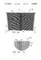
- FIGS. 2a and 2b are a fragmentary schematic plan view and a local blown-up view, respectively, of a portion of a sector illustrating the surface collection channels which lead filtrate into a drainage bore within the sector;
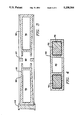
- FIG. 3 is a cross-sectional view of a sector and its drainage bore taken along line 3--3 of FIG. 2a and illustrating the sealed hollow of the prior art beneath the sector deck;
- FIG. 4 is a sectional view, as in FIG. 3, illustrating one embodiment of the transit volume control provided in the invention
- FIG. 5 is a sectional view along line 5--5 of FIG. 4 showing further detail of the embodiment of the invention shown in FIG. 4;
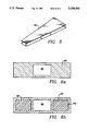
- FIGS. 6a and 6b illustrate, in cross-section, two alternative embodiments of the transit volume control device of the present invention.
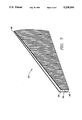
- FIG. 7 illustrates another embodiment of the invention in which the sector has an "open volume” configuration.
- FIG. 1 shows a cross-sectional end view of a typical disc filter installation operating in a vat 12 containing a slurry S.
- a plurality of hollow filter sectors 20 are affixed (by conventional means) to a rotatable hollow shaft 16 which contains a plurality of core drainage channels 18, at least one such channel for each sector (or leaf) 20.
- Each sector 20 is adapted to be mounted upon hollow shaft 16, such that the core drainage channels 18 are in flow communication with at least one drainage bore (not shown) in each sector 20.
- the truncated wedge shape of the filter sector 20 allows it to be installed between the opposing channels of support towers 14 and to be clamped in place by a circumferential retaining band 60 of sequentially attached segments, by individual clamp members 80 fastened to support towers 14, by clamp band segments integral to each sector, or by other commonly known methods.
- the person 22 is shown to give a scale reference for the size of the filter sectors 20.
- each disc comprised of a plurality of sectors 20 mounted on hollow shaft 16 and held in place by support towers 14, to rotate, in either direction through a slurry S contained within vat 12.
- slurry liquid penetrates through the sector surfaces and into the sector drainage bores within each sector 20, due to an applied pressure differential, and is extracted through the hollow filtrate accessible volume of disc sector 20 and core drainage channels 18. This causes a filter cake of the fibrous solid portion of the slurry, which is retained on the surface of sector 20. This build-up continuously from submersion to emergence of each sector from the slurry.
- the filter cake on the surfaces of sectors 20 itself acts as a filtering medium, the filtrate removed during later stages of operation is clearer than that which is removed during earlier stages and is normally drained separately from the early, or cloudy filtrate, by conventional valving (not shown).
- differential pressure is still being applied to remove filtrate accumulated within the hollow sectors 20 and core drainage channels 18. The effects of gravity will also aid the drainage of each sector 20 toward core drainage channel 18.
- the filter cake on each of the surfaces of sectors 20 is removed by a conventional so-called "knock-off shower” (not shown), which is common in the art.
- FIGS. 2a and 2b illustrate the face of a sector 20 and show further detail of the surface flow channels 55, support towers 14, retaining band 60, surface drain holes 57, surface ridges 50, and the sector drainage bore 80 (shown in dashed lines).
- the sector 20 is mounted between support towers 14 and is retained in place by a circumferential retainer band 60 which is installed in segments as the sectors are installed.
- ridges 50 define a number of symmetric flow channels 55 which allow filtrate to drain through drain holes 57 into drainage bore 80.
- the drainage bore is shown at the center of sector 20 as a matter of convenience only and is not limited to that location.
- the bore may be coextensive with the sector face and may also be divided so that it comprises two or more separate bores within each sector. Its configuration and location is determined, at least in part, by considerations of strength and fluid flow, which are functions of sector material selection and filter design capacity.
- drainage channels increase in cross-section from a minimum size near the periphery to a maximum size near the drainage core in order to handle the cumulative volume of filtrate which flows in each location. This may be accomplished also by adding more channels as the core drainage channel is approached.
- FIG. 3 A sectional view from line 3--3 of FIG. 2a is seen in FIG. 3 and illustrates the sealed hollow volume 70 used in the prior art to limit transit volume in disc filters.
- drainage bore 80 is shown in more detail as is support tower 14, sector surface ridges 50, surface drainage channels 55, and drain holes 57.
- the divergence (or increase in cross-section) of flow channels 55, as described above, is clearly shown.
- the body of sector 20 is a single piece which may be molded from an appropriate polymeric material or may be fabricated from parts made from corrosion resistant metal or other materials.
- Hollow volumes 70 are sealed fluid tight to eliminate them from the transit volume of the sector. As long as that seal lasts, the sector performs acceptably. When the seal begins to leak and the sector fills with liquor, the filtrate split becomes less selective, and the added weight causes high stresses on support towers 14, hollow shaft 16, and sector 20. Moreover, when leaks become large enough, hollow volumes 70 become part of the transit volume.
- FIGS. 4 and 5 illustrate one embodiment of the invention which may be applied to new sectors or as a retrofit in existing filter sectors if the hollow volumes have an amenable configuration.
- Sector 20 is shown with drainage bore 80 and hollow volumes 70.
- hollow volumes 70 are shown with displacement wedges 72 in place, a situation which precludes liquor from the slurry from entering the hollow volume 70 and thereby limits transit volume and increases scavenging ratio.
- Displacement wedges 72 are made from a foamed plastic, such as polypropylene or from other lightweight fluid impervious material, are shaped to be insertable into the volumes 70, and are fixed therein by any suitable means (not shown).
- FIGS. 6a and 6b Another embodiment of the invention is shown in FIGS. 6a and 6b, in which sector 20 is molded without hollow volumes other than drainage bore 80 from a solid homopolymer, i.e., a single polymer, in FIG. 6a; and in which it is molded about permanent cores 66 in FIG. 6b.
- the option in FIG. 6b is preferable: because the cores 66 may be made from low density and low strength relatively inexpensive material since their only function is to occupy volume. Once a minimum level of strength and chemical resistance in the cores 66 is satisfied, further increases in properties are not needed.
- the solid-molded sector of FIG. 6a is stronger but more costly and heavier than the option of FIG. 6b.
- 6b can also be attained by molding a sector 20 with drainage bore 80 and hollow volumes 70, as shown, for example, in FIG. 3, and by foaming-in-place an appropriate polymer to fill hollow volumes 70.
- Foaming-in-place provides the advantages of complete filling of, conformance to the shape of, and ease of installation in the hollow volumes 70 of sector 20.
- FIG. 7 presents an open option in which the interior of sector 20 is completely open to the slurry in the vat 12 except for the drainage bore 80.
- the sector faces are separated and supported by the drainage bore 80 and by under-deck bracing (not shown) as required.
- under-deck bracing not shown
- Sectors 20 may be constituted of stainless steel, a polymeric composite material, or other appropriate materials or combinations thereof.
- the support towers 14, core channels 18, and hollow shaft 16 may also be made of the same materials.
Landscapes
- Chemical & Material Sciences (AREA)
- Chemical Kinetics & Catalysis (AREA)
- Filtration Of Liquid (AREA)
Priority Applications (8)
| Application Number | Priority Date | Filing Date | Title |
|---|---|---|---|
| US07/923,707 US5238564A (en) | 1992-07-31 | 1992-07-31 | Method and apparatus for control of filtrate volume in a disc filter |
| PCT/US1993/003645 WO1994003256A1 (en) | 1992-07-31 | 1993-04-15 | Method and apparatus for control of filtrate volume in a disc filter |
| EP93910647A EP0610455A4 (de) | 1992-07-31 | 1993-04-15 | Methode und vorrichtung zum regeln des filtratvolumens in einem scheibenfilter. |
| FI941485A FI941485A0 (fi) | 1992-07-31 | 1993-04-15 | Menetelmä ja laite suodatteen määrällisen tilavuuden valvomiseksi kiekkosuodattimessa |
| JP6505262A JPH06511431A (ja) | 1992-07-31 | 1993-04-15 | 円板フィルタ内のろ液体積を制御する方法と装置 |
| BR9305592A BR9305592A (pt) | 1992-07-31 | 1993-04-15 | Processo e aparelho para o controle do volume de massa filtrada em um filtro de disco |
| CA002119032A CA2119032A1 (en) | 1992-07-31 | 1993-04-15 | Method and apparatus for control of filtrate volume in a disc filter |
| NO941013A NO304061B1 (no) | 1992-07-31 | 1994-03-21 | Fremgangsmåte og anordning for styring av filtratvolum i et skivefilter |
Applications Claiming Priority (1)
| Application Number | Priority Date | Filing Date | Title |
|---|---|---|---|
| US07/923,707 US5238564A (en) | 1992-07-31 | 1992-07-31 | Method and apparatus for control of filtrate volume in a disc filter |
Publications (1)
| Publication Number | Publication Date |
|---|---|
| US5238564A true US5238564A (en) | 1993-08-24 |
Family
ID=25449137
Family Applications (1)
| Application Number | Title | Priority Date | Filing Date |
|---|---|---|---|
| US07/923,707 Expired - Fee Related US5238564A (en) | 1992-07-31 | 1992-07-31 | Method and apparatus for control of filtrate volume in a disc filter |
Country Status (8)
| Country | Link |
|---|---|
| US (1) | US5238564A (de) |
| EP (1) | EP0610455A4 (de) |
| JP (1) | JPH06511431A (de) |
| BR (1) | BR9305592A (de) |
| CA (1) | CA2119032A1 (de) |
| FI (1) | FI941485A0 (de) |
| NO (1) | NO304061B1 (de) |
| WO (1) | WO1994003256A1 (de) |
Cited By (5)
| Publication number | Priority date | Publication date | Assignee | Title |
|---|---|---|---|---|
| AT401355B (de) * | 1994-09-08 | 1996-08-26 | Andritz Patentverwaltung | Scheibenfilter zum abtrennen von flüssigkeiten aus einer suspension, insbesondere faserstoffsuspension |
| US5766466A (en) * | 1995-06-20 | 1998-06-16 | Peterson; John Gary | Sectors for rotary disc filters having flow channels that are parallel and aligned toward elongate side channels at radial sides of the sector |
| US6113783A (en) * | 1996-09-19 | 2000-09-05 | Kvaerner Pulping As | Device in a filter sector for a rotating filter disc |
| US20140197093A1 (en) * | 2011-08-29 | 2014-07-17 | Karl Gabrielsson | Filter segment with a light weight frame |
| CN116943322A (zh) * | 2023-07-12 | 2023-10-27 | 山东金普分析仪器有限公司 | 一种废水处理用转筒式过滤设备 |
Citations (1)
| Publication number | Priority date | Publication date | Assignee | Title |
|---|---|---|---|---|
| US4686040A (en) * | 1985-02-20 | 1987-08-11 | Bjarne Nilsson | Disc filter element for a rotatable disc filter |
Family Cites Families (2)
| Publication number | Priority date | Publication date | Assignee | Title |
|---|---|---|---|---|
| US3438505A (en) * | 1967-01-27 | 1969-04-15 | Improved Machinery Inc | Filter segment for disc filters |
| US3917534A (en) * | 1974-04-17 | 1975-11-04 | Plastic Tech Inc | Filter sector |
-
1992
- 1992-07-31 US US07/923,707 patent/US5238564A/en not_active Expired - Fee Related
-
1993
- 1993-04-15 FI FI941485A patent/FI941485A0/fi unknown
- 1993-04-15 CA CA002119032A patent/CA2119032A1/en not_active Abandoned
- 1993-04-15 BR BR9305592A patent/BR9305592A/pt not_active Application Discontinuation
- 1993-04-15 JP JP6505262A patent/JPH06511431A/ja active Pending
- 1993-04-15 EP EP93910647A patent/EP0610455A4/de not_active Withdrawn
- 1993-04-15 WO PCT/US1993/003645 patent/WO1994003256A1/en not_active Ceased
-
1994
- 1994-03-21 NO NO941013A patent/NO304061B1/no unknown
Patent Citations (1)
| Publication number | Priority date | Publication date | Assignee | Title |
|---|---|---|---|---|
| US4686040A (en) * | 1985-02-20 | 1987-08-11 | Bjarne Nilsson | Disc filter element for a rotatable disc filter |
Cited By (7)
| Publication number | Priority date | Publication date | Assignee | Title |
|---|---|---|---|---|
| AT401355B (de) * | 1994-09-08 | 1996-08-26 | Andritz Patentverwaltung | Scheibenfilter zum abtrennen von flüssigkeiten aus einer suspension, insbesondere faserstoffsuspension |
| US5792352A (en) * | 1994-09-08 | 1998-08-11 | Andritz-Patentverwaltungs-Gesellschaft M.B.H. | Disc filter and filter elements |
| US5766466A (en) * | 1995-06-20 | 1998-06-16 | Peterson; John Gary | Sectors for rotary disc filters having flow channels that are parallel and aligned toward elongate side channels at radial sides of the sector |
| US6113783A (en) * | 1996-09-19 | 2000-09-05 | Kvaerner Pulping As | Device in a filter sector for a rotating filter disc |
| US20140197093A1 (en) * | 2011-08-29 | 2014-07-17 | Karl Gabrielsson | Filter segment with a light weight frame |
| US9968875B2 (en) * | 2011-08-29 | 2018-05-15 | Gl&V Luxembourg S.A.R.L. | Filter segment with a light weight frame |
| CN116943322A (zh) * | 2023-07-12 | 2023-10-27 | 山东金普分析仪器有限公司 | 一种废水处理用转筒式过滤设备 |
Also Published As
| Publication number | Publication date |
|---|---|
| NO941013D0 (no) | 1994-03-21 |
| CA2119032A1 (en) | 1994-02-17 |
| JPH06511431A (ja) | 1994-12-22 |
| FI941485L (fi) | 1994-03-30 |
| EP0610455A1 (de) | 1994-08-17 |
| EP0610455A4 (de) | 1995-05-10 |
| FI941485A7 (fi) | 1994-03-30 |
| WO1994003256A1 (en) | 1994-02-17 |
| FI941485A0 (fi) | 1994-03-30 |
| NO941013L (no) | 1994-03-21 |
| NO304061B1 (no) | 1998-10-19 |
| BR9305592A (pt) | 1996-01-02 |
Similar Documents
| Publication | Publication Date | Title |
|---|---|---|
| US3363774A (en) | Rotary drum filter | |
| CA1098046A (en) | Apparatus and method for filtering a fibrous material with a disc filter | |
| US5942113A (en) | Solid-liquid separating filter medium for sewage, waste water, etc | |
| US5515776A (en) | Worm press with tapered shaft core | |
| US3409139A (en) | Rotary-vacuum filter drum and suction box arrangement | |
| US4676901A (en) | Rotating disc filter | |
| US3794178A (en) | Rotary drum filtering apparatus and unitary drainage sectors therefor | |
| EP3810300B1 (de) | Vakuumfilter | |
| US5453194A (en) | Back-flushing filter device for the filtration of highly viscous liquids | |
| US3438505A (en) | Filter segment for disc filters | |
| US3306457A (en) | Drum filter | |
| US4781835A (en) | Disk concentrators | |
| EP0577854B1 (de) | Filtervorrichtung | |
| US5470471A (en) | Anti-rewet deck for press rolls | |
| US5238564A (en) | Method and apparatus for control of filtrate volume in a disc filter | |
| CA1313967C (en) | Double diffuser with backflush pistons | |
| EP0611324A4 (de) | Wiederbefeuchtungsverhindernder, modularer scheibensektor mit niedrigem gewicht. | |
| US8281936B2 (en) | Vacuum washer drum having a center and end drains and method for draining | |
| CA2172257C (en) | Cross braced vacuum washer | |
| US4333836A (en) | Cellular drum filter for the dewatering of fiber suspensions | |
| US8137568B2 (en) | Rotary drum vacuum filter | |
| US7229527B2 (en) | Method for the controlled thickening of low consistency fiber suspensions | |
| US5034120A (en) | Method for keeping a screen or filter surface clear | |
| SU1824241A1 (en) | Centrifugal separator for separation of three-component suspension | |
| AT526990B1 (de) | Ventilvorrichtung für einen Scheibenfilter |
Legal Events
| Date | Code | Title | Description |
|---|---|---|---|
| AS | Assignment |
Owner name: INGERSOLL-RAND COMPANY A CORPORATION OF NEW JERSE Free format text: ASSIGNMENT OF ASSIGNORS INTEREST.;ASSIGNOR:LUTHI, OSCAR;REEL/FRAME:006234/0436 Effective date: 19920715 |
|
| FPAY | Fee payment |
Year of fee payment: 4 |
|
| FEPP | Fee payment procedure |
Free format text: PAYOR NUMBER ASSIGNED (ORIGINAL EVENT CODE: ASPN); ENTITY STATUS OF PATENT OWNER: LARGE ENTITY |
|
| FPAY | Fee payment |
Year of fee payment: 8 |
|
| REMI | Maintenance fee reminder mailed | ||
| LAPS | Lapse for failure to pay maintenance fees | ||
| STCH | Information on status: patent discontinuation |
Free format text: PATENT EXPIRED DUE TO NONPAYMENT OF MAINTENANCE FEES UNDER 37 CFR 1.362 |
|
| FP | Lapsed due to failure to pay maintenance fee |
Effective date: 20050824 |