US5225743A - High voltage switch - Google Patents
High voltage switch Download PDFInfo
- Publication number
- US5225743A US5225743A US07/791,709 US79170991A US5225743A US 5225743 A US5225743 A US 5225743A US 79170991 A US79170991 A US 79170991A US 5225743 A US5225743 A US 5225743A
- Authority
- US
- United States
- Prior art keywords
- electrode
- switch
- set forth
- axis
- cavity
- Prior art date
- Legal status (The legal status is an assumption and is not a legal conclusion. Google has not performed a legal analysis and makes no representation as to the accuracy of the status listed.)
- Expired - Fee Related
Links
- 239000012212 insulator Substances 0.000 claims description 5
- 230000003247 decreasing effect Effects 0.000 claims description 4
- 239000004417 polycarbonate Substances 0.000 claims description 4
- 229920000515 polycarbonate Polymers 0.000 claims description 4
- 230000005855 radiation Effects 0.000 claims description 4
- 230000001960 triggered effect Effects 0.000 claims description 4
- 239000010453 quartz Substances 0.000 claims description 3
- VYPSYNLAJGMNEJ-UHFFFAOYSA-N silicon dioxide Inorganic materials O=[Si]=O VYPSYNLAJGMNEJ-UHFFFAOYSA-N 0.000 claims description 3
- 239000004020 conductor Substances 0.000 claims description 2
- 239000011810 insulating material Substances 0.000 claims description 2
- NINIDFKCEFEMDL-UHFFFAOYSA-N Sulfur Chemical compound [S] NINIDFKCEFEMDL-UHFFFAOYSA-N 0.000 claims 1
- 229910052717 sulfur Inorganic materials 0.000 claims 1
- 239000011593 sulfur Substances 0.000 claims 1
- 238000010304 firing Methods 0.000 description 5
- RYGMFSIKBFXOCR-UHFFFAOYSA-N Copper Chemical compound [Cu] RYGMFSIKBFXOCR-UHFFFAOYSA-N 0.000 description 4
- 239000010949 copper Substances 0.000 description 4
- 229910052802 copper Inorganic materials 0.000 description 4
- 229910018503 SF6 Inorganic materials 0.000 description 3
- 230000007423 decrease Effects 0.000 description 3
- SFZCNBIFKDRMGX-UHFFFAOYSA-N sulfur hexafluoride Chemical compound FS(F)(F)(F)(F)F SFZCNBIFKDRMGX-UHFFFAOYSA-N 0.000 description 3
- 229910000881 Cu alloy Inorganic materials 0.000 description 2
- 238000000034 method Methods 0.000 description 2
- 239000000523 sample Substances 0.000 description 2
- WFKWXMTUELFFGS-UHFFFAOYSA-N tungsten Chemical compound [W] WFKWXMTUELFFGS-UHFFFAOYSA-N 0.000 description 2
- 239000010937 tungsten Substances 0.000 description 2
- 229910052721 tungsten Inorganic materials 0.000 description 2
- 229910001369 Brass Inorganic materials 0.000 description 1
- 239000004677 Nylon Substances 0.000 description 1
- 229910001080 W alloy Inorganic materials 0.000 description 1
- 229910045601 alloy Inorganic materials 0.000 description 1
- 239000000956 alloy Substances 0.000 description 1
- 230000015572 biosynthetic process Effects 0.000 description 1
- 239000010951 brass Substances 0.000 description 1
- 230000003749 cleanliness Effects 0.000 description 1
- 239000000356 contaminant Substances 0.000 description 1
- 230000001351 cycling effect Effects 0.000 description 1
- 238000010586 diagram Methods 0.000 description 1
- 238000010891 electric arc Methods 0.000 description 1
- 230000005684 electric field Effects 0.000 description 1
- 239000000835 fiber Substances 0.000 description 1
- 238000009413 insulation Methods 0.000 description 1
- 229920001778 nylon Polymers 0.000 description 1
- 230000003287 optical effect Effects 0.000 description 1
- 230000002265 prevention Effects 0.000 description 1
- 238000007789 sealing Methods 0.000 description 1
- 238000001228 spectrum Methods 0.000 description 1
- 229960000909 sulfur hexafluoride Drugs 0.000 description 1
Images


Classifications
-
- H—ELECTRICITY
- H01—ELECTRIC ELEMENTS
- H01T—SPARK GAPS; OVERVOLTAGE ARRESTERS USING SPARK GAPS; SPARKING PLUGS; CORONA DEVICES; GENERATING IONS TO BE INTRODUCED INTO NON-ENCLOSED GASES
- H01T2/00—Spark gaps comprising auxiliary triggering means
- H01T2/02—Spark gaps comprising auxiliary triggering means comprising a trigger electrode or an auxiliary spark gap
Definitions
- This invention relates generally to high voltage switches and more particularly to a spark gap switch triggered by a change in pressure.
- Spark gap switches have many uses in high power applications with short switching time intervals or short pulse durations.
- the basic spark gap switch includes a housing and a pair of electrodes. When a high voltage is applied to the electrodes, an arc is created between the electrodes and current is allowed to pass through the switch.
- the main electrodes of a spark gap switch are basically pins or rods with the ends pointing at each other. Therefore, when an arc forms between the electrodes all the current passes in the area between the ends of the electrodes. This creates a high current density and furthermore a high inductance switch.
- the subject invention is directed at overcoming one or more of the problems as set forth above.
- a switch in one aspect of the present invention, includes a housing, which forms a cavity, and first and second electrodes.
- the first electrode has an inner surface.
- the inner surface has a generally circular cross-section perpendicular to an axis and extends along the cavity in a first direction along the axis, forming a hollow tube.
- the second electrode has a generally circular cross-section perpendicular to the axis and extends into the cavity in a second direction along the axis. The second electrode extends at least partially into the hollow tube formed by the first electrode.
- an apparatus including a switching element.
- the switching element includes a housing and first and second electrodes and forms a pressurized cavity filled with gas.
- the first and second electrodes have a predetermined spatial relationship with respect to each other within said pressurized cavity.
- the pressure within said cavity is controllably increased and decreased between an open pressure value and a closed pressure value.
- the gas acts as an insulator between the first and second electrodes under said open pressure value and as a short circuit under said closed pressure value.
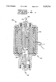
- FIG. 1 is a stylized representation of a spark gap switch having first, second, and third electrodes, according to the an embodiment of the present invention
- FIG. 1A is a stylized representation of a spark gap switch having first and second electrodes, according to a second embodiment of the present invention
- FIG. 1B is a stylized representation of the second electrode of FIGS. 1 and 2 and a trigger electrode, according to an embodiment of the present invention
- FIG. 2 is a stylized representation of an alternate embodiment of the second electrode of FIGS. 1 and 2;
- FIG. 3 is a block diagram illustrating the operation of the spark gap switch of FIG. 1.
- a switch 100 having a housing 102 is provided.
- the housing 102 includes a body 120 and first and second end portions or endcaps 106,110.
- the housing 102 has a generally circular cross-section centered about an axis 112.
- the body 120 and first and second endcaps 106,110 form a pressurized cavity 104.
- the first and second endcaps 106,110 are composed of an electrically conducting material, preferably copper or a copper alloy.
- the body 120 is composed of an insulating material. In the preferred embodiment, the body 120 is composed of polycarbonate.
- the body 120 has an exterior surface or wall 122 which is, preferably, grooved.
- the body 120 has an interior surface or wall 124 which is also, preferably, grooved.
- the first endcap 106 forms a first electrode.
- the present invention is not limited to such and the first endcap and the first electrode may be separate.
- the first electrode 106 has an inner surface 108.
- the inner surface 108 has a generally circular cross-section perpendicular to the axis 112.
- the inner surface 108 extends along the cavity 104 in a first direction along the axis 112, forming a hollow tube.
- a second electrode 114 has first and second ends 116,118 and in the preferred embodiment is connected to the second endcap 110 at the first end 116.
- the second end 118 of the second electrode 114 has a generally circular cross-section perpendicular to the axis 112.
- the second end 118 of the second electrode 114 extends into the cavity 104 in a second direction along the axis 112.
- the first and second directions are opposite.
- the second end 118 of the second electrode 114 extends at least partially into the hollow tube formed by the first electrode 102.
- the first and second electrodes are composed of a copper alloy.
- the second electrode 114 includes a replaceable tip portion.
- the tip portion is composed of tungsten or a tungsten alloy.
- a suitable alloy is Elkonite, which consists of tungsten and copper.
- the second electrode 114 is tapered. That is, the thickness of the second end portion 118 of the second electrode 114 decreases toward the end, thereby, increasing the distance between the first and second electrodes 106,114.
- the tapering of the second electrode 114 minimizes the firing or arcing of the switch 100 toward the end of the second electrode 114 and reducing the wear.
- the operating characteristics of the switch 100 may be modified by varying the distance between the first and second electrodes 106,114. In the preferred embodiment, this is accomplished by changing the outside diameter of the second electrode 114.
- FIG. 2 an alternate second electrode 202 for the switch 100 of FIG. 1 is shown. As illustrated, for a small diameter electrode, the first end portion is flanged to add mechanical stability.
- the switch 100 includes a third electrode 130.
- the third electrode 130 is electrically connected to the first electrode 106.
- the third electrode 130 has a generally circular cross-section perpendicular to the axis 112 and extends along the axis 112 in the first direction.
- the second electrode 114 forms a second hollow tube.
- the third electrode 130 extends into the second hollow tube.
- the distance between the second and third electrodes 114,130 (D1) is preferably less than the distance between said first and second electrodes 106,114 (D2).
- the switch 100 may include an insulating insert 132 situated in the hollow tube formed by the second electrode 114.
- the insulating tube 132 reduces the weight, adds mechanical stability, and reduces the gas volume for faster on/off cycling response.
- the insulating tube 132 is also composed of a polycarbonate and forms part of a gas outlet port 126.
- a quartz window 132 permits introduction of a brief pulse of ultraviolet radiation to trigger the switch 100.
- the use of the quartz window 132 to trigger the switch 132 is used as an alternative triggering method or to assist at higher repetition rates to fire the switch with appropriate synchronization.
- a fiber optic probe 134 senses the optical spectra emitted when the switch is firing. As shown, the probe 134, penetrate approximately halfway into the body 120 because polycarbonates allow visible light to pass.
- the housing 102 is held together by a plurality of screws.
- the screws are composed of nylon. Sealing gaskets or O-rings seal the juncture between the endcaps 106,110 and the body 120.
- the switch 100 includes at least one gas inlet port 128',128" in the body 120 of the housing 102 (two are shown).
- the switch 100 can be triggered by three methods, individually or in combination: ultraviolet radiation (described above), pressure (described below), and by a trigger electrode 136, as shown in FIG. 1B.
- the trigger electrode 138 includes a copper tube 140 and a brass ball 142.
- the copper tube 140 passes through the center of the insulator 132 and the second electrode 114.
- the trigger electrode 138 is fed a trigger pulse signal through a screw 146 and washer 144 arrangement, as shown.
- the trigger pulse signal creates an arc between the trigger electrode 138 and the second electrode 114 by locally extorting the electric field.
- the arc ionizes the gas in the cavity 104, triggering an arc between the first and second electrodes 106,114.
- An insulator 148 isolates the screw 146 from the second electrode 114.
- a means 300 forms a short circuit between said first and second electrodes 106,114.
- the means 300 controllably increases and decreases the pressure of the gas within the cavity 104 between an open value and a closed value.
- the gas acts as an insulator between the first and second electrodes 106,114 under said open value and as a short circuit between the first and second electrodes 106,114 under said closed value.
- the switch 100 is opened and closed to supply electrical power to a load 302.
- the load 302 is connected to the first electrode 106.
- the second electrode 114 is electrically connected to a high voltage power supply 308.
- a high pressure gas supply 304 is provided for pressurizing the cavity 104.
- the cavity 104 is pressurized with sulfur hexafluoride gas, SF 6 .
- a pressure release valve 306 releases the pressure from the cavity 104.
- the cavity 104 is pressurized and unpressurized by actuation of the high pressure gas supply and pressure release valve 304,306 through a gas inlet port 128 and a gas outlet port 126, respectively, by a controlling means 310.
- the present invention is adapted to provide a highly reliable switch 100 that is durable, compact, low cost, and more easily serviced.
- the switch 100 is generally operated by controllably increasing and decreasing the pressure within the switch 100. This has two advantages. First, it automatically cycles the gas within the cavity 104, thereby lowering the temperature. This aids in keeping the electrodes cool. Second, by changing the gas within the switch 100 between firings, contaminants are removed from the cavity 104. Furthermore, when the gas is released, the pressure gradient created between the the first and second electrodes 106,114 favors the formation of an arc discharge away from the end of the second electrode 114. This produces a lower and more uniform current density.
- the controlling means 310 closes the switch 100 by opening the pressure relief valve 306 and releasing the SF6 gas.
- the switch 100 is pressurized to approximately 6 atmospheres. However, pressures up to 12 atmospheres may be used.
- the switch 100 When the pressure reaches a certain value (depending upon the switch characteristics) the switch 100 will fire. When the switch 100 fires, an arc is formed between the first and second electrodes 106,114.
- the electrodes 106,114 are designed to provide greater surface area for current to flow between the first and second electrodes. This effectively decreases the current density, the ohmic resistance, and the inductance of the switch 100.
- the third electrode 130 further reduces the resistance and inductance of the switch 100.
- an arc will form between the second and third electrodes 114,130.
- This second arc occurs after the first arc because the gap between the second and third electrodes, 114,130 (D1), is slightly larger than the gap between the first and second electrodes 106,114 (D2).
- the first arc produces ionizing ultraviolet radiation which expedites the triggering of the second arc.
- the grooves in the inner and outer surfaces 122,124 of the body 120 aid in increasing the voltage insulation between the endcaps and electrodes 106,110,114,130.
- the tapering at the end of the second electrode 114 helps reduce the wear at the tip, switching on speed, further reduces the inductance, and increases the lifespan of the electrode 114.
- the switch has been tested between 15-300 kV (in an external air environment). However, by scaling the design up, the switch should be able to handle voltages up into the megavolt range.
- the operating characteristic of the switch 100 can be modified by changing the diameters of the first and/or second electrode 106,114 or by scaling the dimensions of the entire switch 100.
Landscapes
- Spark Plugs (AREA)
- Circuit Arrangements For Discharge Lamps (AREA)
- Control Of Combustion (AREA)
- Electronic Switches (AREA)
- Arc-Extinguishing Devices That Are Switches (AREA)
- Push-Button Switches (AREA)
Priority Applications (5)
| Application Number | Priority Date | Filing Date | Title |
|---|---|---|---|
| US07/791,709 US5225743A (en) | 1991-11-14 | 1991-11-14 | High voltage switch |
| JP4299840A JPH05242949A (ja) | 1991-11-14 | 1992-11-10 | 高電圧スイッチ |
| AT92310359T ATE136166T1 (de) | 1991-11-14 | 1992-11-12 | Hochspannungsschalter |
| EP92310359A EP0546692B1 (de) | 1991-11-14 | 1992-11-12 | Hochspannungsschalter |
| DE69209463T DE69209463T2 (de) | 1991-11-14 | 1992-11-12 | Hochspannungsschalter |
Applications Claiming Priority (1)
| Application Number | Priority Date | Filing Date | Title |
|---|---|---|---|
| US07/791,709 US5225743A (en) | 1991-11-14 | 1991-11-14 | High voltage switch |
Publications (1)
| Publication Number | Publication Date |
|---|---|
| US5225743A true US5225743A (en) | 1993-07-06 |
Family
ID=25154556
Family Applications (1)
| Application Number | Title | Priority Date | Filing Date |
|---|---|---|---|
| US07/791,709 Expired - Fee Related US5225743A (en) | 1991-11-14 | 1991-11-14 | High voltage switch |
Country Status (5)
| Country | Link |
|---|---|
| US (1) | US5225743A (de) |
| EP (1) | EP0546692B1 (de) |
| JP (1) | JPH05242949A (de) |
| AT (1) | ATE136166T1 (de) |
| DE (1) | DE69209463T2 (de) |
Cited By (1)
| Publication number | Priority date | Publication date | Assignee | Title |
|---|---|---|---|---|
| US11329480B1 (en) * | 2021-03-05 | 2022-05-10 | Advanced Fusion Systems Llc | Series static spark gap for EMP protection |
Families Citing this family (6)
| Publication number | Priority date | Publication date | Assignee | Title |
|---|---|---|---|---|
| JP3338409B2 (ja) | 1999-03-02 | 2002-10-28 | コリアン アクセレレータ アンド プラズマ リサーチ アソシエーション | パルスパワーシステム |
| DE10118210B4 (de) * | 2001-04-11 | 2012-02-23 | Dehn + Söhne Gmbh + Co. Kg | Gekapselter Überspannungsableiter mit einer Funkenstreckenanordnung |
| SE522144C2 (sv) * | 2002-05-13 | 2004-01-20 | Abb Ab | Elektisk anordning och förfarande |
| CN105071225B (zh) * | 2015-08-27 | 2017-01-18 | 桂林理工大学 | 一种气密性间隙可调的火花隙开关 |
| CN105186293B (zh) * | 2015-08-27 | 2017-03-22 | 桂林理工大学 | 气密性间隙可调的火花隙开关的运行方法 |
| RU2770190C1 (ru) * | 2021-02-04 | 2022-04-14 | Федеральное государственное бюджетное образовательное учреждение высшего образования Иркутский государственный университет путей сообщения (ФГБОУ ВО ИрГУПС) | Силовой искровой разрядник |
Citations (8)
| Publication number | Priority date | Publication date | Assignee | Title |
|---|---|---|---|---|
| US2512538A (en) * | 1949-07-26 | 1950-06-20 | Atomic Energy Commission | Electric discharge device |
| US3510716A (en) * | 1967-11-17 | 1970-05-05 | Ite Imperial Corp | Adjustable three electrode spark gap |
| US4267484A (en) * | 1979-08-28 | 1981-05-12 | The United States Of America As Represented By The Secretary Of The Air Force | Parallel multi-electrode spark gap switch |
| US4442383A (en) * | 1982-03-08 | 1984-04-10 | Hill Alan E | Plasma switch |
| US4563608A (en) * | 1982-11-08 | 1986-01-07 | The United States Of America As Represented By The United States Department Of Energy | Gas flow stabilized megavolt spark gap for repetitive pulses |
| US4912369A (en) * | 1988-09-16 | 1990-03-27 | United States Of America As Represented By The Secretary Of The Navy | High PRF high current switch |
| US4970433A (en) * | 1988-10-12 | 1990-11-13 | The United States Of America As Represented By The United States Department Of Energy | Apparatus and method for tuned unsteady flow purging of high pulse rate spark gaps |
| US4990831A (en) * | 1988-10-12 | 1991-02-05 | The United States Of America As Represented By The United States Department Of Energy | Spark gap switch system with condensable dielectric gas |
Family Cites Families (4)
| Publication number | Priority date | Publication date | Assignee | Title |
|---|---|---|---|---|
| DE3523299A1 (de) * | 1985-06-28 | 1987-01-08 | Beru Werk Ruprecht Gmbh Co A | Vorfunkenstrecke |
| EP0229303A1 (de) * | 1985-12-18 | 1987-07-22 | Cerberus Ag | Funkenstrecke, insbesondere zur Verwendung als Vorfunkenstrecke einer Zündkerze eines Verbrennungsmotors |
| JPS63313487A (ja) * | 1987-06-13 | 1988-12-21 | Horiba Ltd | ギヤツプスイツチ |
| FR2673334A1 (fr) * | 1991-02-22 | 1992-08-28 | Alcatel Cable | Eclateur haute energie declenche par laser. |
-
1991
- 1991-11-14 US US07/791,709 patent/US5225743A/en not_active Expired - Fee Related
-
1992
- 1992-11-10 JP JP4299840A patent/JPH05242949A/ja active Pending
- 1992-11-12 EP EP92310359A patent/EP0546692B1/de not_active Expired - Lifetime
- 1992-11-12 DE DE69209463T patent/DE69209463T2/de not_active Expired - Fee Related
- 1992-11-12 AT AT92310359T patent/ATE136166T1/de not_active IP Right Cessation
Patent Citations (8)
| Publication number | Priority date | Publication date | Assignee | Title |
|---|---|---|---|---|
| US2512538A (en) * | 1949-07-26 | 1950-06-20 | Atomic Energy Commission | Electric discharge device |
| US3510716A (en) * | 1967-11-17 | 1970-05-05 | Ite Imperial Corp | Adjustable three electrode spark gap |
| US4267484A (en) * | 1979-08-28 | 1981-05-12 | The United States Of America As Represented By The Secretary Of The Air Force | Parallel multi-electrode spark gap switch |
| US4442383A (en) * | 1982-03-08 | 1984-04-10 | Hill Alan E | Plasma switch |
| US4563608A (en) * | 1982-11-08 | 1986-01-07 | The United States Of America As Represented By The United States Department Of Energy | Gas flow stabilized megavolt spark gap for repetitive pulses |
| US4912369A (en) * | 1988-09-16 | 1990-03-27 | United States Of America As Represented By The Secretary Of The Navy | High PRF high current switch |
| US4970433A (en) * | 1988-10-12 | 1990-11-13 | The United States Of America As Represented By The United States Department Of Energy | Apparatus and method for tuned unsteady flow purging of high pulse rate spark gaps |
| US4990831A (en) * | 1988-10-12 | 1991-02-05 | The United States Of America As Represented By The United States Department Of Energy | Spark gap switch system with condensable dielectric gas |
Cited By (2)
| Publication number | Priority date | Publication date | Assignee | Title |
|---|---|---|---|---|
| US11329480B1 (en) * | 2021-03-05 | 2022-05-10 | Advanced Fusion Systems Llc | Series static spark gap for EMP protection |
| WO2022187461A1 (en) * | 2021-03-05 | 2022-09-09 | Advanced Fusion Systems Llc | Series static spark gap for emp protection |
Also Published As
| Publication number | Publication date |
|---|---|
| EP0546692A1 (de) | 1993-06-16 |
| DE69209463T2 (de) | 1996-08-14 |
| EP0546692B1 (de) | 1996-03-27 |
| DE69209463D1 (de) | 1996-05-02 |
| JPH05242949A (ja) | 1993-09-21 |
| ATE136166T1 (de) | 1996-04-15 |
Similar Documents
| Publication | Publication Date | Title |
|---|---|---|
| KR101415415B1 (ko) | 융삭 플라즈마 건 | |
| US5225743A (en) | High voltage switch | |
| US11145477B2 (en) | Short-circuiting device for use in low-voltage and medium-voltage systems for the protection of property and persons | |
| US4027187A (en) | Supersonic spark gap switch | |
| EP0201430A3 (de) | Gasisolierter Leistungsschalter mit Lichtbogenbeblasung | |
| US6037715A (en) | Spark switch having coaxial electrodes with increased electrode surface area exposure | |
| CA1086393A (en) | Gas actuated high voltage bushing | |
| US5850125A (en) | Pseudospark switch having an insulator between electrodes | |
| Frank et al. | High repetition rate pseudo-spark switches for laser applications | |
| US4565911A (en) | High-voltage circuit-breaker | |
| CA2137882A1 (en) | Striker pin device for an electric fuse | |
| CA1196941A (en) | Brake and operation indicator for a high-voltage switch | |
| US5510668A (en) | Spark gap with low breakdown voltage jitter | |
| US2683235A (en) | Lightning arrester | |
| DE8027885U1 (de) | Schutzschalter zur Unterbrechung eines Stromkreises unter Sprengwirkung | |
| RU95115860A (ru) | Дугогасительное устройство высоковольтного газонаполненного автокомпрессионного выключателя | |
| US3267320A (en) | Magnetic blowout spark gap switch | |
| RU2091891C1 (ru) | Высоковольтный газовый выключатель с автогенерацией дугогасящего потока | |
| USH878H (en) | High voltage insulators for long, linear switches | |
| RU2219611C2 (ru) | Быстродействующий предохранитель | |
| SU1117749A1 (ru) | Трубчатый разр дник | |
| SU838808A1 (ru) | Электрический газовый компресси-ОННый ВыКлючАТЕль | |
| US2454849A (en) | Electric circuit interrupter | |
| EP1074032A1 (de) | Unterbrechung für einen primärschutzschalter | |
| RU181339U1 (ru) | Устройство дугогасительное высоковольтного выключателя |
Legal Events
| Date | Code | Title | Description |
|---|---|---|---|
| AS | Assignment |
Owner name: CATERPILLAR INC.,, ILLINOIS Free format text: ASSIGNMENT OF ASSIGNORS INTEREST.;ASSIGNORS:CODINA, GEORGE G.;RICHARDS, THOMAS J.;BRANDT, EVERETT G.;REEL/FRAME:005915/0961 Effective date: 19911108 |
|
| FEPP | Fee payment procedure |
Free format text: PAYER NUMBER DE-ASSIGNED (ORIGINAL EVENT CODE: RMPN); ENTITY STATUS OF PATENT OWNER: LARGE ENTITY Free format text: PAYOR NUMBER ASSIGNED (ORIGINAL EVENT CODE: ASPN); ENTITY STATUS OF PATENT OWNER: LARGE ENTITY |
|
| FPAY | Fee payment |
Year of fee payment: 4 |
|
| FPAY | Fee payment |
Year of fee payment: 8 |
|
| AS | Assignment |
Owner name: CAPELLA CORPORATION, CALIFORNIA Free format text: ASSIGNMENT OF ASSIGNORS INTEREST;ASSIGNOR:CATERPILLAR INC.;REEL/FRAME:013897/0981 Effective date: 20030321 |
|
| REMI | Maintenance fee reminder mailed | ||
| REMI | Maintenance fee reminder mailed | ||
| LAPS | Lapse for failure to pay maintenance fees | ||
| STCH | Information on status: patent discontinuation |
Free format text: PATENT EXPIRED DUE TO NONPAYMENT OF MAINTENANCE FEES UNDER 37 CFR 1.362 |
|
| FP | Lapsed due to failure to pay maintenance fee |
Effective date: 20050706 |