US522231A - Joseph sachs - Google Patents
Joseph sachs Download PDFInfo
- Publication number
- US522231A US522231A US522231DA US522231A US 522231 A US522231 A US 522231A US 522231D A US522231D A US 522231DA US 522231 A US522231 A US 522231A
- Authority
- US
- United States
- Prior art keywords
- circuit
- magnet
- box
- auxiliary
- battery
- Prior art date
- Legal status (The legal status is an assumption and is not a legal conclusion. Google has not performed a legal analysis and makes no representation as to the accuracy of the status listed.)
- Expired - Lifetime
Links
- 238000010276 construction Methods 0.000 description 2
- 230000000694 effects Effects 0.000 description 2
- 230000000284 resting effect Effects 0.000 description 2
- 239000002699 waste material Substances 0.000 description 2
- 241001139376 Allas Species 0.000 description 1
- 239000004020 conductor Substances 0.000 description 1
- 238000010586 diagram Methods 0.000 description 1
- 230000037431 insertion Effects 0.000 description 1
- 238000003780 insertion Methods 0.000 description 1
- 239000000463 material Substances 0.000 description 1
- 239000002184 metal Substances 0.000 description 1
Images

Classifications
-
- G—PHYSICS
- G08—SIGNALLING
- G08B—SIGNALLING OR CALLING SYSTEMS; ORDER TELEGRAPHS; ALARM SYSTEMS
- G08B25/00—Alarm systems in which the location of the alarm condition is signalled to a central station, e.g. fire or police telegraphic systems
- G08B25/12—Manually actuated calamity alarm transmitting arrangements emergency non-personal manually actuated alarm, activators, e.g. details of alarm push buttons mounted on an infrastructure
Definitions
- the present invention relates to auxiliary fire alarm signal systems, that is, to systems in which fire alarm or street boxes can be released or operated to send their signals over a main circuit by means of one or more auxiliary or local circuits having suitable circuitcontrollers and devices at a distance from the street boxes.
- auxiliary fire alarm signal systems that is, to systems in which fire alarm or street boxes can be released or operated to send their signals over a main circuit by means of one or more auxiliary or local circuits having suitable circuitcontrollers and devices at a distance from the street boxes.
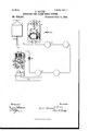
- Figure 1 is a diagram of one system embodying the improvements.
- Fig. 2 is a side view of the tell-tale and relay grammatic view of a slightly different arrangement of circuits and devices.
- l is a street or fire telegraph box, from which extends a circuit 2, to the fire alarm station, this circuit being controlled'by a make and break mechanism in the box, indicating the box number, inthe well-known manner, and which is not shown in the-drawings.
- the motor of this signal device is pref-r.
- the terminals 11, 14, are preferably arranged so that they can'beconnected for'insertion between them ofa conducting plug,if;*for-any reason,
- a relatively weak battery B say two cells,and such circuit extends to several circuit-controlling and return-call devices or sending boxes l5, connected in series in the circuit.
- Each of said -devices consists of means forma'intaining the .circuit closed normally, such, for example, as
- the circuit is first broken by moving the switch handle from the contact 17.
- the circuit is again made when the switch arm reaches contact 18, which is connected by a wire to the spring 19, which normally rests on the upper edge of the annunciator plate 20, as describedin my application above referred to.
- the switch arm is locked or held on each contact by any suitable means, e. g. by a pin on the upper face of each contact which engages with a hole in the switch arm.
- Said annunciator plate is pivoted at 21, and
- This signal mechanism can be wound up by means of the spindle 30, and is normally held from running down by the arm 31, which prevents the fan or regulator from moving.
- 32 is a high resistance relay magnet, interposed directly in the auxiliary circuit 12 and normally sufficiently energized by the small battery B to hold its armature 33 attracted,with the contact 34 resting against the adjustable contact 35, to which one terminal of the magnet is connected.
- the opposite adjustable contact 36 is connected by means of a wire 37 to the post 38, against which the circuit making and breaking arm 39 normally rests, and said arm isconnected to the comparatively large battery 40.
- 41 is aretracting spring for the armature, but it is insulated from the contact 36 by the interposed non conducting thread 42. From the upper pole of the battery extends a wire 43 to the other terminal of the magnet 32, and the main wire of the auxiliary circuit 12 extends to the pivoted armature 44 normally resting on the back stop 1 street box, that is,
- 46 is a magnet, one terminal of which is connected to said armature, the other terminal of which is connected through a cell or battery to earth.
- the normal circuit is from battery B to arm 16, wire 17, and on to sueceeding sending boxes, to armature 33 at the telltale box, through magnet 32, to armature 44, to succeeding sending boxes, through magnet13 to the opposite pole of the battery.
- the circuit-controller at the upper left corner of Fig. 1 is operated by moving switch 16 from the position shown toward contact 18.
- the first effect will be to break the auxiliary circuit including battery B, thereby de-energizing magnet 32 and allowing its armature to fall against its back stop 36, thereby cutting out said magnet and including the large battery 40 directly in the auxiliary circuit, and also releasing the telltale signal.
- the switch reaches the contact 18, the auxiliary circuit being closed to the large battery 40, the magnet 13 will be energized, attracting its armature and releasing the street or fire alarm box, allowing it to send in the fire alarm.
- circuit-breakers which break and then again automatically make circuit, as in the construction described in the application above referred to, since the permanent circuit-breaker prevents several signals being sent from the same box to indicate the same fire, as may happen when the permanent circuit-breaker is not employed.
- the safety magnet 46 will be energized by its grounded battery, raising armature 44 and breaking the auxiliary circuit at contact 45, or otherwise changing the circuit so as to operate the telltale signal, making it necessary for the proper oliicer to examine the system or makeinquiries to find the cause of trouble.
- the telltale motor is about run down, the arm connected with spindle 30 will strike the pivoted lever 39, turning it away from contact 38 and opening the circuit of the large battery to prevent waste thereof.
- Fig. 3 the mechanism at box 1 is supposed to be constructed and operated as already described.
- the mechanism is slightly different.
- An indicating or galvanometer needle47 is pivoted adjacent to a section or coil of wire 48 in the auxiliary circuit, this needle being held, when current is passing, so as to point to the indication O. K., as shown, and serving to indicate the condition of the circuit.
- the magnet 26 of the return-call device is connected directly to contact 17 of the switch, the opposite terminal being connected bywire 49 to the'auxiliary circuit, the other'parts of the mechanism being as already described.
- the small battery B is omitted, and the large battery 50 is permanently placed directly in the auxiliary circuit and in series with the high resistance magnet 51, which corresponds to the magnet 32 of Fig. 1.
- the armature lever 52 of this magnet is pivoted at 53, and has a springpressed pawl 54 to engage the teethof the ,ratchet-wheel 55, adapted whenmoved to carry with it the disk 56 on thesame shaft 58 is a pivoted lever carrying an adjustablescrew 59 which rests on the periphery of the wheel 56, the spring 60 serving to draw the lever 58 toward the wheel.
- a detent 61 for the mechanism of the telltale apparatus.
- 62 is an adjustable contact, against which the arm 58. may move under very nearly the same as that already d6.
- the large battery 50 serves the function of both the small battery B and the large battery 40 in Fig. 1, and material waste of current is prevented by the high resistance magnet 51 which is normally directly in series with the battery.
- the releasing magnet 13 is energized by simply shunting this high resistance magnet. Since the operation of the fire alarm mechanism requiresa break and then a make of the auxiliary circuit, it is not liable to oc-. cur accidentally.
- What I claim isp 1. The combination of a fire-alarm or similar box, a magnetic releasing or operating device therefor, an auxiliary-circuit including said device, and one or more sending boxes or stations having circuit-controller and return-call devices, a magneticallycontrolled switching device in the auxiliarycircuit, and
Landscapes
- Business, Economics & Management (AREA)
- Emergency Management (AREA)
- Physics & Mathematics (AREA)
- General Physics & Mathematics (AREA)
- Fire Alarms (AREA)
Description
I (No Model.) 2 Sheets-Sheet 1.
In V i V AUXILIARY FIRE ALARM SIGNAL SYSTEM- I No. 522,231.
Paten ted July s, 1894.
' 35 M 11? 3 tO'LMMdSM N. D. c.
(No Model.) 2 snow-sheet 2.
- J. SACHS.
AUXILIARY FIRE ALARM SIGNAL SYSTEM. No. 522,231. I Patentdd Jul'y 3,1894.
wi bwmeo v guwmboz Tn: mums mus no, PHOYO-LITNO wAsmuoTun. n, c.
:1 NITED STATES PATENT- OFF CE.
JOSEPH SACHS, OF. NEWlYoRK, N. Y.
AUXILIARY FIRE-ALARM SIGNAL SY'STEM.
SPECIFICATION forming art of Letters raters No. 522,231, elated July 3, 1894.
Applicationfiled November 8,1392. Serial No. 451,305. momma.)
To all. whom it may concern.- 5
Be it known that I, JOSEPH SACHS, a citi'ze of the United States, residing at New York city, in the county and State of NewYork,
have invented a certain new and useful Improvement in Auxiliary Fire -Alarm-Signal Y Systems, of which the following is a specificatron.
The present invention relates to auxiliary fire alarm signal systems, that is, to systems in which fire alarm or street boxes can be released or operated to send their signals over a main circuit by means of one or more auxiliary or local circuits having suitable circuitcontrollers and devices at a distance from the street boxes. In my application, Serial No. 437,814,. filed June 24, 1892, I have described such a system in which circuit-controllers, return-calls, and tell-tale devices are connected in multiple arc to the auxiliary circuit. The present invention constitutes an improvement thereon, and the invention consists in the several combinations hereinafter described and set forth in theclaims.
According to the present improvement, the
. devices are connected in the auxiliary circuit v1n series rather than in multiple arc, since this is found preferable for various reasons, and the construction is such that false alarms on the main or fire alarm circuit are prevented, and accidental grounds are at once indicated.
In the drawings, Figure 1 is a diagram of one system embodying the improvements. Fig. 2 is a side view of the tell-tale and relay grammatic view of a slightly different arrangement of circuits and devices.
In Fig. 1, l is a street or fire telegraph box, from which extends a circuit 2, to the fire alarm station, this circuit being controlled'by a make and break mechanism in the box, indicating the box number, inthe well-known manner, and which is not shown in the-drawings. The motor of this signal deviceis pref-r.
stop 9, against which the springpressed pivoted piece 10 normally bears, the piece lObeing. supported in the circuit terminal device 11, from which extends one of the wires of the local or auxiliary circuit 12. 13 is a magnet adapted to move the armature lever 7 under proper circumstances, to operate or release the signal mechanism, one terminal of r the magnet being connected'to the armature 7 and the other being c'onnectedfto a terminal or connecting device l4,"asshown. The terminals 11, 14, are preferably arranged so that they can'beconnected for'insertion between them ofa conducting plug,if;*for-any reason,
it should be desirable'to shortcircuit the magnet, and from the terminal 14 extends the other'wire of .the local or'auxiliary circuit. In said circuit, preferablynear to or in the box'l, is placed acomparatively weak battery B, say two cells,and such circuit extends to several circuit-controlling and return-call devices or sending boxes l5, connected in series in the circuit. Each of said -devices consists of means forma'intaining the .circuit closed normally, such, for example, as
the switch arm 16 and the low resistance conductor 17, and means for breaking the circuit and then making it, in such manner as to include the return-call magnet. In the arrangement illustrated, the circuit is first broken by moving the switch handle from the contact 17. The circuit is again made when the switch arm reaches contact 18, which is connected by a wire to the spring 19, which normally rests on the upper edge of the annunciator plate 20, as describedin my application above referred to. The switch arm is locked or held on each contact by any suitable means, e. g. by a pin on the upper face of each contact which engages with a hole in the switch arm.
Said annunciator plate is pivoted at 21, and
has avhook or pin-22 normally engaged by the pivoted detent23, which is pushed back when the armature 24: is attracted, but is-arrested by the hook 22 striking arm" 25;,and which falls when thea'rmature 24 and arm 25 again move toward the right, allas described in said application. 26 is the return -call magnet, one terminal being connected to the metal 19, and the other terminal being connected to the wire 12. At about the center of the auxframe at 27, thence to the shutter and spring iliary circuit, is placed a tell-tale safety and switching device, and the working battery. 28 is a tell-tale signal mechanism adapted to send signals over a circuit 29 leading to any desired station or office, as more fully described in the application above referred to. This signal mechanism can be wound up by means of the spindle 30, and is normally held from running down by the arm 31, which prevents the fan or regulator from moving. 32 is a high resistance relay magnet, interposed directly in the auxiliary circuit 12 and normally sufficiently energized by the small battery B to hold its armature 33 attracted,with the contact 34 resting against the adjustable contact 35, to which one terminal of the magnet is connected. The opposite adjustable contact 36 is connected by means of a wire 37 to the post 38, against which the circuit making and breaking arm 39 normally rests, and said arm isconnected to the comparatively large battery 40. 41 is aretracting spring for the armature, but it is insulated from the contact 36 by the interposed non conducting thread 42. From the upper pole of the battery extends a wire 43 to the other terminal of the magnet 32, and the main wire of the auxiliary circuit 12 extends to the pivoted armature 44 normally resting on the back stop 1 street box, that is,
45. 46 is a magnet, one terminal of which is connected to said armature, the other terminal of which is connected through a cell or battery to earth. The normal circuit is from battery B to arm 16, wire 17, and on to sueceeding sending boxes, to armature 33 at the telltale box, through magnet 32, to armature 44, to succeeding sending boxes, through magnet13 to the opposite pole of the battery.
Suppose that the circuit-controller at the upper left corner of Fig. 1 is operated by moving switch 16 from the position shown toward contact 18. The first effect will be to break the auxiliary circuit including battery B, thereby de-energizing magnet 32 and allowing its armature to fall against its back stop 36, thereby cutting out said magnet and including the large battery 40 directly in the auxiliary circuit, and also releasing the telltale signal. Then when the switch reaches the contact 18, the auxiliary circuit being closed to the large battery 40, the magnet 13 will be energized, attracting its armature and releasing the street or fire alarm box, allowing it to send in the fire alarm. As soon as the armature lever7 is moved by the magnet, the circuit breaking lever 10 is thrown over to the leftvby its spring, thus permanently (that is, until positively reset) opening the auxiliary circuit, thereby sending a return call by releasing armature 24 and making it necessary for the proper officer to go to the street box and manually re-set the arm 10 before the auxiliary circuit can again be utilized to send a signal from box 1. This feature of a permanent circuit-breaker at the a circuit-breaker which i when it is once operated cannot be operated .and having adeep notch 57.
again until positively reset, is found preferable to circuit-breakers which break and then again automatically make circuit, as in the construction described in the application above referred to, since the permanent circuit-breaker prevents several signals being sent from the same box to indicate the same fire, as may happen when the permanent circuit-breaker is not employed.
Should a ground accidentally occur at any point in the auxiliary circuit, the safety magnet 46 will be energized by its grounded battery, raising armature 44 and breaking the auxiliary circuit at contact 45, or otherwise changing the circuit so as to operate the telltale signal, making it necessary for the proper oliicer to examine the system or makeinquiries to find the cause of trouble. When the telltale motor is about run down, the arm connected with spindle 30 will strike the pivoted lever 39, turning it away from contact 38 and opening the circuit of the large battery to prevent waste thereof.
It will be seen that with the auxiliary circuitand its batteries and devices arranged as described, it is impossible for accidental grounds or short circuits to operate the fire alarmbox. While thecircuitbreakingspring 19 is shown, this is not necessary, since the auxiliary circuit is left open by the arm 10, as already described. Morethan one aux iliary circuit may extend from the same street box, as indicated at 12'.
In Fig. 3, the mechanism at box 1 is supposed to be constructed and operated as already described. At the sending boxes 15, 15, the mechanism is slightly different. An indicating or galvanometer needle47 is pivoted adjacent to a section or coil of wire 48 in the auxiliary circuit, this needle being held, when current is passing, so as to point to the indication O. K., as shown, and serving to indicate the condition of the circuit. The magnet 26 of the return-call device,.instead of being connected to the frame, is connected directly to contact 17 of the switch, the opposite terminal being connected bywire 49 to the'auxiliary circuit, the other'parts of the mechanism being as already described. In this modified system, the small battery B is omitted, and the large battery 50 is permanently placed directly in the auxiliary circuit and in series with the high resistance magnet 51, which corresponds to the magnet 32 of Fig. 1. The armature lever 52 of this magnet is pivoted at 53, and has a springpressed pawl 54 to engage the teethof the ,ratchet-wheel 55, adapted whenmoved to carry with it the disk 56 on thesame shaft 58 is a pivoted lever carrying an adjustablescrew 59 which rests on the periphery of the wheel 56, the spring 60 serving to draw the lever 58 toward the wheel. At the lower end of the lever 52 is a detent 61 for the mechanism of the telltale apparatus. 62 is an adjustable contact, against which the arm 58. may move under very nearly the same as that already d6.
scribed. When an arm 16 is moved toward the left at any of the boxes 15, the first effect will be to open the auxiliary circuit, thereby tie-energizing magnet 51 and allowing the spring sto move the armature lever and the pawl 54 toward the left, engaging an advanced tooth of the ratchet 55, at the same time releasing the tell-tale. When the arm 16 strikes the contact 17, magnet 51 will be again energized, although the releasing magnet 13 in the street box (see Fig. 1) will not be energized, owing to the resistance of magnet 51. Said magnet 51, attracting its armature, turns the ratchet 55 and wheel 56 onespace, allowing screw 59 to fall into notch 57,bringing lever 58 and contact 62 together, shortvcircuiting the high resistance magnet 51,
thereby allowing sufficient current to pass to magnet 13 to operate it, sending in the fire alarm signal and permanently breaking the auxiliary circuit. ,In this system, the large battery 50 serves the function of both the small battery B and the large battery 40 in Fig. 1, and material waste of current is prevented by the high resistance magnet 51 which is normally directly in series with the battery. The releasing magnet 13 is energized by simply shunting this high resistance magnet. Since the operation of the fire alarm mechanism requiresa break and then a make of the auxiliary circuit, it is not liable to oc-. cur accidentally.
In both ofthe systems shown and described, only a single or simple series circuit is required, leading to the fire-alarm box. At each sending box the normal circuit includes only the switch contacts and arm, and'the low resistance wire 17 Operation of anyone of the devices 15 does not directly throw the working current onto the auxiliary circuit, but it changes the condition of that circuit so that the automatic switch at the tell-tale station makes'the working battery operativeon the circuit to energize magnet 13. The special advantage of this is that it makes it possible to use a simple series circuit, normally having a current on it of insnfficient strength to energize the main working magnet, in the manner described.
What I claim isp 1. The combination of a fire-alarm or similar box, a magnetic releasing or operating device therefor, an auxiliary-circuit including said device, and one or more sending boxes or stations having circuit-controller and return-call devices, a magneticallycontrolled switching device in the auxiliarycircuit, and
small battery and a single closed net at or near the'center of aworking battery or source of current adapted to operate said magnetic device controlled by said switch, substantially as described.
2. The combination of a fire alarm or similar box, a magnetic releasing or operating device therefor, sending boxes each having circuit controlling and return call devices, a magnetically controlled switching device, a small battery and a single closed electric circuit containing the releasing device, the sending .box devices, small battery and the switching device in series, a main battery brought into said circuit by the electrically controlled switching device when the sending box is operated and thereby operating the releasing device substantially as specified. 1
3. The combination of a fire alarm or similar' box, a magnetic releasing or operating device therefor, sending boxes each having circuit controlling and return call devices, a magnetically controlled switching device, a small battery and a single -closed electric circuit containing the releasing device, the sending box devices, small battery and the switching device in series; a main battery brought'into said circuit by the electrically controlled switching device when the sending box is operated and thereby operating the releasing device, and a telltale brought into action by said switch substantially as specified.
'4. The combination of a fire alarm or similar box, a magnetic releasing or operating device therefor, sending boxes each having circuit controlling and return call devices, a magnetically-controlled switching device, a
electric circuit containing the releasing device, the sending box devices, small battery and the switching device in series, a main battery brought into said circuit by the electrically controlled switching device when the sending box is operated and thereby operating the'releasing device, and atelltale brought into action by said switch, a branch to the auxiliary releasing circuitand an electro mag-net and battery, andground in the branch arranged to operate the tell-tale if there is a ground in the auxiliary releasing circuit, specified. v
5. The combination of a fire-alarm or similar box, a releasing or operating magnet therefor, an auxiliary circuit including said magsubstantially as net, and one or more sending boxes, each having a normally breaking. and
call device, of circuit,
closed short circuit,'a circuit making switch, and a returnthe latter being normally cut out a high resistance switching magv the auxiliary circuit, and an armature therefor, said armature controlling the circuit in such manner as to throw a working current thereon when oper-v ated, substantially as described.
6. The combination in a fire alarm signal of a main alarm box and the releasing or opan auxiliary circuit boxes through which the auxilerating device therefor, and sending iary circuit passes, a switch magnet in the auxiliary circuit and a working generator controlled by the switch, there being a magnet and switch in each sending box, the switch acting first to break the auxiliary circuit and thereby operate the magnetic switch and throw the working battery into the auxiliary circuit, and then to again close the auxiliary circuit and direct the main current from the working battery through the return call magnet and through the magnetic operating device of the main alarm box and sending the signal substantially as specified.
7. The combination, with a fire-alarm box or similar device and an auxiliary releasing circuit, and a working generator, of an automatic switch for throwing said generator into circuit, a tell-tale signal, and a circuit-breaker in the circuit, the generator operated by the tell-tale mechanism, substantially as de- 20 JOSEPH sAcns.
Witnesses:
EUGENE CONRAN, CHARLES M. CATLIN.
Publications (1)
| Publication Number | Publication Date |
|---|---|
| US522231A true US522231A (en) | 1894-07-03 |
Family
ID=2591026
Family Applications (1)
| Application Number | Title | Priority Date | Filing Date |
|---|---|---|---|
| US522231D Expired - Lifetime US522231A (en) | Joseph sachs |
Country Status (1)
| Country | Link |
|---|---|
| US (1) | US522231A (en) |
-
0
- US US522231D patent/US522231A/en not_active Expired - Lifetime
Similar Documents
| Publication | Publication Date | Title |
|---|---|---|
| US522231A (en) | Joseph sachs | |
| US1840637A (en) | Burglar alarm system | |
| US474670A (en) | Automatic fire-alarm | |
| US365726A (en) | Electric circuit-testing apparatus | |
| US254336A (en) | Maeion h | |
| US498448A (en) | sachs | |
| US410318A (en) | Fire-alarm system | |
| US611638A (en) | Irjs peters co | |
| US506841A (en) | Electric alarm system | |
| US839873A (en) | Fire-alarm and watch-service system. | |
| US514279A (en) | sachs | |
| US1188654A (en) | Electrical apparatus. | |
| US758724A (en) | Signaling system. | |
| US477071A (en) | Annunciator | |
| US478789A (en) | denio | |
| US828420A (en) | Fire-alarm system. | |
| US815993A (en) | Transfer-switch for testing circuits. | |
| US329468A (en) | Automatic fire-alarm telegraph | |
| US1324732A (en) | Signal-transmitting system | |
| US773870A (en) | Automatic electrical signaling system. | |
| US1225937A (en) | Factory-fire-drill system. | |
| US378983A (en) | smith | |
| US623441A (en) | Automatic fire and burglar alarm | |
| US632964A (en) | Electric-call system. | |
| US421853A (en) | Automatic fire-alarm system |