US5220751A - Processing installation, especially for dental purposes, with two combined different processing apparatuses - Google Patents
Processing installation, especially for dental purposes, with two combined different processing apparatuses Download PDFInfo
- Publication number
- US5220751A US5220751A US07/727,476 US72747691A US5220751A US 5220751 A US5220751 A US 5220751A US 72747691 A US72747691 A US 72747691A US 5220751 A US5220751 A US 5220751A
- Authority
- US
- United States
- Prior art keywords
- suctioning
- grinding
- milling
- processing installation
- source
- Prior art date
- Legal status (The legal status is an assumption and is not a legal conclusion. Google has not performed a legal analysis and makes no representation as to the accuracy of the status listed.)
- Expired - Fee Related
Links
Images

Classifications
-
- B—PERFORMING OPERATIONS; TRANSPORTING
- B23—MACHINE TOOLS; METAL-WORKING NOT OTHERWISE PROVIDED FOR
- B23Q—DETAILS, COMPONENTS, OR ACCESSORIES FOR MACHINE TOOLS, e.g. ARRANGEMENTS FOR COPYING OR CONTROLLING; MACHINE TOOLS IN GENERAL CHARACTERISED BY THE CONSTRUCTION OF PARTICULAR DETAILS OR COMPONENTS; COMBINATIONS OR ASSOCIATIONS OF METAL-WORKING MACHINES, NOT DIRECTED TO A PARTICULAR RESULT
- B23Q11/00—Accessories fitted to machine tools for keeping tools or parts of the machine in good working condition or for cooling work; Safety devices specially combined with or arranged in, or specially adapted for use in connection with, machine tools
- B23Q11/0042—Devices for removing chips
- B23Q11/0046—Devices for removing chips by sucking
Definitions
- the present invention relates to a processing or machining installation, especially for dental purposes, with two combined different processing apparatuses.
- dust is produced which is not only damaging to the health of the person working with the apparatus, but also presents a contamination of the environment.
- the invention as described in detail hereinbelow, has as an object to provide a processing or treating installation of that kind which not only possesses a common control and suctioning arrangement, but also incorporates a control circuit for the currently activated processing or treating apparatus, through the intermediary of which there is always compulsorily actuated the suctioning device in conjunction therewith.
- German Petty Patent 66 10 274 there has become known the utilization of a multi-purpose worktool which consists of two different worktools which can be selectively operated from a common motor.
- U.S. Pat. No. 3,977,127 sets forth a multi-purpose worktool, wherein a plurality of worktool shafts are driven through the intermediary of a belt drive from a common motor.
- a belt grinding machine is equipped with a suctioning device.
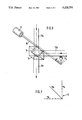
- FIG. 1 illustrates a perspective front view of the inventive combined processing or treating apparatus
- FIG. 2 illustrates a schematic representation of the common switch lever for the apparatus and the positions thereof.
- FIG. 3 illustrates a perspective view of the switching device.
- reference numeral 1 generally designates the combined processing or treating apparatus;
- reference numeral 2 identifies the belt grinder apparatus with the grinding surface 4, the grinding belt 5 and the grinding table 6; whereas reference numeral 3 designates the milling apparatus with the milling worktool 7, the milling support surface 8 and a pivot lever 9 for the positioning of plaster cast or gypsum models which are to be treated or machined and for protection against any unintentional touching of the milling worktool 7.
- Reference numeral 10 identifies the housing for the suctioning control with the switching lever 11; reference numeral 12 refers to the electrical switch, reference numeral 13 relates to the suctioning conduits, reference numeral 16 designates the suctioning device with a blower or the like; and reference numeral 17 identifies the base portion of the combined processing or treating apparatus 1 with the suctioning device.
- reference numeral 11a represents the neutral zero-position for the switching lever 11
- 11b defines its "grinding position” in which the grinding apparatus 2 is activated in conjunction with its suctioning device
- reference numeral 11c identifies the "milling position” in which the milling apparatus 3 is activated in conjunction with its suctioning device.
- the reference numeral 10 again identifies the housing for the circuit
- reference numeral 11 designates the switching lever
- reference numeral 12 identifies the electrical switch
- 13a identifies the suctioning conduit leading from the grinding apparatus 2
- reference numeral 13b is the conduit leading from the milling apparatus 3
- reference numeral 13c relates to the common exhaust-air conduit which leads to the suctioning arrangement 16 in the housing base portion 17.
- a three-way valve 14 which, in accordance with the switching, connects either the suctioning conduit 13a or the suctioning conduit 13b with the common exhaust-air conduit 13c.
Landscapes
- Engineering & Computer Science (AREA)
- Mechanical Engineering (AREA)
- Dental Tools And Instruments Or Auxiliary Dental Instruments (AREA)
- Finish Polishing, Edge Sharpening, And Grinding By Specific Grinding Devices (AREA)
- Manipulator (AREA)
Abstract
A processing or machining installation, especially for dental purposes, with two combined different processing apparatuses. The installation possesses a common control and suctioning arrangement, and also incorporates a control circuit for the currently activated processing or treating apparatus, through the intermediary of which there is always compulsorily actuated the suctioning device in conjunction therewith.
Description
1. Field of the Invention
The present invention relates to a processing or machining installation, especially for dental purposes, with two combined different processing apparatuses.
During operation or working with apparatuses of that type, in particular grinding apparatuses, dust is produced which is not only damaging to the health of the person working with the apparatus, but also presents a contamination of the environment.
Consequently, the invention as described in detail hereinbelow, has as an object to provide a processing or treating installation of that kind which not only possesses a common control and suctioning arrangement, but also incorporates a control circuit for the currently activated processing or treating apparatus, through the intermediary of which there is always compulsorily actuated the suctioning device in conjunction therewith.
The advantages of this invention are predicated on a space-saving compact construction in a compulsory suctioning device, and in essence, in an energy-saving manner with only a single suctioning device for the activated processing apparatus.
2. Discussion of the Prior Art
From the disclosure of German Petty Patent 66 10 274 there has become known the utilization of a multi-purpose worktool which consists of two different worktools which can be selectively operated from a common motor.
The disclosure of U.S. Pat. No. 3,977,127 sets forth a multi-purpose worktool, wherein a plurality of worktool shafts are driven through the intermediary of a belt drive from a common motor.
As set forth in the disclosure of U.S. Pat. No. 4,221,081, a belt grinding machine is equipped with a suctioning device.
Reference may now be had to the following detailed description of an exemplary embodiment of an apparatus pursuant to the invention, taken in conjunction with the accompanying drawings; in which:
FIG. 1 illustrates a perspective front view of the inventive combined processing or treating apparatus;
FIG. 2 illustrates a schematic representation of the common switch lever for the apparatus and the positions thereof; and
FIG. 3 illustrates a perspective view of the switching device.
In FIG. 1 of the drawings, reference numeral 1 generally designates the combined processing or treating apparatus; reference numeral 2 identifies the belt grinder apparatus with the grinding surface 4, the grinding belt 5 and the grinding table 6; whereas reference numeral 3 designates the milling apparatus with the milling worktool 7, the milling support surface 8 and a pivot lever 9 for the positioning of plaster cast or gypsum models which are to be treated or machined and for protection against any unintentional touching of the milling worktool 7.
In FIG. 2 of the drawing, reference numeral 11a represents the neutral zero-position for the switching lever 11, 11b defines its "grinding position" in which the grinding apparatus 2 is activated in conjunction with its suctioning device; reference numeral 11c identifies the "milling position" in which the milling apparatus 3 is activated in conjunction with its suctioning device.
In FIG. 3, the reference numeral 10 again identifies the housing for the circuit, reference numeral 11 designates the switching lever, reference numeral 12 identifies the electrical switch; 13a identifies the suctioning conduit leading from the grinding apparatus 2; reference numeral 13b is the conduit leading from the milling apparatus 3; both of which conduits terminate in the housing 10, and reference numeral 13c relates to the common exhaust-air conduit which leads to the suctioning arrangement 16 in the housing base portion 17. Arranged in the housing 10 is a three-way valve 14 which, in accordance with the switching, connects either the suctioning conduit 13a or the suctioning conduit 13b with the common exhaust-air conduit 13c.
Claims (10)
1. A processing installation for dental workpieces, including two operatively combined working apparatus, one said working apparatus being a grinding apparatus having an upright grinding surface and the other said working apparatus being a milling apparatus having a milling worktool with a vertically directed axis of rotation; a grinding support surface for the workpieces on said grinding apparatus; a milling support surface for the workpieces on said milling apparatus; a suctioning device having a single suctioning source commonly connected with said two working apparatuses including a suctioning conduit connected to said suctioning source, said suctioning conduit having a Y-connection extending into first and second branch conduits, said first branch conduit leading to the grinding support surface and said second branch conduit leading to the milling support surface for the workpieces; valve means in said Y-connection for selectively connecting said first and second branch conduits with said suctioning source; switching means operatively connected with said valve means; and electrical control circuit means commonly connected with said working apparatuses and said switching means whereby activation of a selective one of said working apparatus by said switching means through said electrical control means concurrently actuates said valve means to connect the branch conduit communicating with said activated working apparatus with said sunctioning source.
2. A processing installation as claimed in claim 1, wherein said switching means comprises a switching lever selectively positionable in a first neutral position for deactivating both said working apparatuses and said suctioning source, a second position for actuating said grinding apparatus and said suctioning source, and a third position for actuating said milling apparatus and suctioning source.
3. A processing installation as claimed in claim 2, wherein said switching lever includes a shaft commonly mounting said electrical control circuit and valve means.
4. A processing installation as claimed in claim 3, wherein said electrical control circuit comprises an electrical switch, and said valve means comprises a three-way valve.
5. A processing installation as claimed in claim 4, wherein said three-way valve is arranged in a housing having connections for three suctioning conduits, a first one of said suctioning conduits leading from the grinding apparatus, a second one of said suctioning conduits leading from the milling apparatus; and a third one of said suctioning conduits being a common exhaust air conduit.
6. A processing installation as claimed in claim 5, wherein said suctioning source includes a suctioning blower located in a base portion of said housing.
7. A processing installation as claimed in claim 1, wherein said grinding apparatus comprises a belt grinding apparatus.
8. A processing installation as claimed in claim 7, wherein said belt grinding apparatus includes a vertically traveling grinding belt; and a horizontal grinding table surface being operatively associated with said grinding belt.
9. A processing installation as claimed in claim 1, wherein said milling apparatus includes a horizontal milling support surface; and a milling tool of said apparatus being pivotable about a vertical axis of rotation and projecting upwardly from said milling support surface.
10. A processing installation as claimed in claim 9, wherein said milling apparatus includes a pivot lever for effectuating the feed of workpieces which are to be processed by said apparatus.
Applications Claiming Priority (2)
| Application Number | Priority Date | Filing Date | Title |
|---|---|---|---|
| DE4021953A DE4021953C2 (en) | 1990-07-10 | 1990-07-10 | Device for processing dental technology products |
| DE4021953 | 1990-07-10 |
Publications (1)
| Publication Number | Publication Date |
|---|---|
| US5220751A true US5220751A (en) | 1993-06-22 |
Family
ID=6410024
Family Applications (1)
| Application Number | Title | Priority Date | Filing Date |
|---|---|---|---|
| US07/727,476 Expired - Fee Related US5220751A (en) | 1990-07-10 | 1991-07-09 | Processing installation, especially for dental purposes, with two combined different processing apparatuses |
Country Status (7)
| Country | Link |
|---|---|
| US (1) | US5220751A (en) |
| JP (1) | JPH04231952A (en) |
| AT (1) | AT400100B (en) |
| CH (1) | CH683896A5 (en) |
| DE (1) | DE4021953C2 (en) |
| FR (1) | FR2664523A1 (en) |
| IT (2) | IT1248582B (en) |
Families Citing this family (2)
| Publication number | Priority date | Publication date | Assignee | Title |
|---|---|---|---|---|
| DE4414936B4 (en) * | 1994-04-28 | 2009-08-06 | Kaltenbach & Voigt Gmbh & Co. Kg | Method for controlling the suction power of a central suction device and device for carrying out the method |
| DE19721393A1 (en) * | 1997-05-22 | 1999-01-07 | Chiron Werke Gmbh | Machine tool |
Citations (10)
| Publication number | Priority date | Publication date | Assignee | Title |
|---|---|---|---|---|
| US1480601A (en) * | 1922-01-20 | 1924-01-15 | Champion Shoe Machinery Compan | Shoe-finishing machine |
| US2231134A (en) * | 1938-05-18 | 1941-02-11 | Marchetta Lorenzo | Shoe repair finishing machine |
| DE705678C (en) * | 1937-11-25 | 1941-05-07 | Werner Himmelmann | Grinding machine, especially milling and cleaning machine for shoes |
| US2470601A (en) * | 1946-07-08 | 1949-05-17 | John R Burke | Dust collecting apparatus |
| DE6610274U (en) * | 1965-10-16 | 1973-09-06 | Hans-Werner Friedlaender | MULTI-PURPOSE TOOL. |
| US3977127A (en) * | 1975-06-25 | 1976-08-31 | Mahnken L Wesley | Multi-purpose hobby finishing apparatus |
| US4221081A (en) * | 1978-08-28 | 1980-09-09 | Everett Charles T | Dust collector system for belt sander |
| US4227902A (en) * | 1977-08-08 | 1980-10-14 | St. Charles Manufacturing Co. | Bench structure with dust collector |
| DE8905017U1 (en) * | 1989-04-21 | 1989-09-21 | Heimer GmbH & Co. Lufttechnik KG, 4800 Bielefeld | Device for extracting dust, chips or similar from cutting or grinding machines |
| US5018319A (en) * | 1989-03-13 | 1991-05-28 | Pauli & Griffin | Pneumatic tube selector mechanism |
Family Cites Families (9)
| Publication number | Priority date | Publication date | Assignee | Title |
|---|---|---|---|---|
| FR1002573A (en) * | 1946-10-25 | 1952-03-07 | Single lever device for controlling one or more moving machine parts | |
| GB677703A (en) * | 1950-02-06 | 1952-08-20 | Werner Winterhoff | Improvements in or relating to trimming, finishing or the like machines |
| US3484075A (en) * | 1967-05-03 | 1969-12-16 | Jack L Weekley | Valve structure |
| CH641663A5 (en) * | 1978-06-05 | 1984-03-15 | Kaltenbach & Voigt | Device for processing workpieces, especially dental laboratory products |
| JPS55157856A (en) * | 1979-05-29 | 1980-12-08 | Mitsubishi Electric Corp | Cathode-ray tube for light supply |
| SE445909B (en) * | 1979-07-06 | 1986-07-28 | Flaekt Ab | PLANT FOR SUGAR TRANSPORT OF WASTE MATERIAL FROM A MULTIPLE LOCAL COLLECTION PLACES TO A COMMON WASTE DISPOSAL |
| JPS59286B2 (en) * | 1979-08-20 | 1984-01-06 | 新日本製鐵株式会社 | Continuous rolling method for pipes |
| JPS60890U (en) * | 1983-06-17 | 1985-01-07 | 岡谷電機産業株式会社 | surge absorption element |
| DE8611859U1 (en) * | 1986-04-30 | 1986-06-19 | Festo Kg, 73734 Esslingen | Connection piece for connecting processing machines having a dust extraction connection to a dust extraction device |
-
1990
- 1990-07-10 DE DE4021953A patent/DE4021953C2/en not_active Expired - Fee Related
-
1991
- 1991-06-19 FR FR9107526A patent/FR2664523A1/en active Pending
- 1991-06-20 AT AT0124191A patent/AT400100B/en not_active IP Right Cessation
- 1991-06-28 IT ITMI911785A patent/IT1248582B/en active IP Right Grant
- 1991-06-28 IT IT000586U patent/ITMI910586U1/en unknown
- 1991-07-09 CH CH2031/91A patent/CH683896A5/en not_active IP Right Cessation
- 1991-07-09 US US07/727,476 patent/US5220751A/en not_active Expired - Fee Related
- 1991-07-10 JP JP3170125A patent/JPH04231952A/en active Pending
Patent Citations (10)
| Publication number | Priority date | Publication date | Assignee | Title |
|---|---|---|---|---|
| US1480601A (en) * | 1922-01-20 | 1924-01-15 | Champion Shoe Machinery Compan | Shoe-finishing machine |
| DE705678C (en) * | 1937-11-25 | 1941-05-07 | Werner Himmelmann | Grinding machine, especially milling and cleaning machine for shoes |
| US2231134A (en) * | 1938-05-18 | 1941-02-11 | Marchetta Lorenzo | Shoe repair finishing machine |
| US2470601A (en) * | 1946-07-08 | 1949-05-17 | John R Burke | Dust collecting apparatus |
| DE6610274U (en) * | 1965-10-16 | 1973-09-06 | Hans-Werner Friedlaender | MULTI-PURPOSE TOOL. |
| US3977127A (en) * | 1975-06-25 | 1976-08-31 | Mahnken L Wesley | Multi-purpose hobby finishing apparatus |
| US4227902A (en) * | 1977-08-08 | 1980-10-14 | St. Charles Manufacturing Co. | Bench structure with dust collector |
| US4221081A (en) * | 1978-08-28 | 1980-09-09 | Everett Charles T | Dust collector system for belt sander |
| US5018319A (en) * | 1989-03-13 | 1991-05-28 | Pauli & Griffin | Pneumatic tube selector mechanism |
| DE8905017U1 (en) * | 1989-04-21 | 1989-09-21 | Heimer GmbH & Co. Lufttechnik KG, 4800 Bielefeld | Device for extracting dust, chips or similar from cutting or grinding machines |
Also Published As
| Publication number | Publication date |
|---|---|
| DE4021953A1 (en) | 1992-01-23 |
| ITMI911785A1 (en) | 1992-12-28 |
| CH683896A5 (en) | 1994-06-15 |
| ATA124191A (en) | 1995-02-15 |
| ITMI910586V0 (en) | 1991-06-28 |
| DE4021953C2 (en) | 1994-05-26 |
| IT1248582B (en) | 1995-01-19 |
| ITMI911785A0 (en) | 1991-06-28 |
| ITMI910586U1 (en) | 1992-01-11 |
| AT400100B (en) | 1995-09-25 |
| JPH04231952A (en) | 1992-08-20 |
| FR2664523A1 (en) | 1992-01-17 |
Similar Documents
| Publication | Publication Date | Title |
|---|---|---|
| JPH10180523A5 (en) | Universal milling and boring machine | |
| CA2208346A1 (en) | Apparatus for machining a workpiece | |
| US5220751A (en) | Processing installation, especially for dental purposes, with two combined different processing apparatuses | |
| JPS58202747A (en) | Dust absorber | |
| EP0331003A3 (en) | A turret tool post for lathes, machining centers performing turning operations, and the like | |
| AU564105B2 (en) | Universal do-it-yourself machine | |
| ATE451198T1 (en) | FIVE-AXIS MACHINE TOOL WITH CONTINUOUS GRINDING DISC DRESSING DEVICE | |
| EP0340681A3 (en) | Turning device for boring or milling machines | |
| JPS6048257A (en) | Ginding or polishing by machining center | |
| CN117324962A (en) | Five-axis turning, milling and grinding integrated machine | |
| EP0358928A3 (en) | Machine-tool | |
| JP2001038502A (en) | Nc lathe | |
| EP0673715A4 (en) | MACHINE FOR MACHINING A GLASS PLATE. | |
| JPH01281840A (en) | Chip removing device | |
| FR2603834B1 (en) | UNIVERSAL MACHINE FOR WORKING WOOD OR SIMILAR MATERIAL | |
| EP0978351A3 (en) | Apparatus having vertically orientated lathes | |
| CN217990987U (en) | Rocker arm drilling equipment with overturning adjusting performance | |
| JPH0545383B2 (en) | ||
| CN219465368U (en) | Precise numerical control lathe based on double procedures | |
| JPH0314296Y2 (en) | ||
| CN2420101Y (en) | Polishing machine | |
| CN113579747A (en) | Automatic processing line for false teeth | |
| CZ7097U1 (en) | Drilling mortising machine | |
| JPH0355140A (en) | Table driving device of working machine | |
| JPS6125449Y2 (en) |
Legal Events
| Date | Code | Title | Description |
|---|---|---|---|
| AS | Assignment |
Owner name: KALTENBACH & VOIGT GMBH & CO. A CORP. OF GERMAN Free format text: ASSIGNMENT OF ASSIGNORS INTEREST.;ASSIGNORS:LANG, HANS-WALTER;WENGER, JOSEF;REEL/FRAME:005780/0681 Effective date: 19910620 |
|
| REMI | Maintenance fee reminder mailed | ||
| LAPS | Lapse for failure to pay maintenance fees | ||
| FP | Lapsed due to failure to pay maintenance fee |
Effective date: 19970625 |
|
| STCH | Information on status: patent discontinuation |
Free format text: PATENT EXPIRED DUE TO NONPAYMENT OF MAINTENANCE FEES UNDER 37 CFR 1.362 |