US5220529A - One-chip first-in first-out memory device having matched write and read operations - Google Patents
One-chip first-in first-out memory device having matched write and read operations Download PDFInfo
- Publication number
- US5220529A US5220529A US07/747,047 US74704791A US5220529A US 5220529 A US5220529 A US 5220529A US 74704791 A US74704791 A US 74704791A US 5220529 A US5220529 A US 5220529A
- Authority
- US
- United States
- Prior art keywords
- write
- read
- signal
- reset signal
- counter
- Prior art date
- Legal status (The legal status is an assumption and is not a legal conclusion. Google has not performed a legal analysis and makes no representation as to the accuracy of the status listed.)
- Expired - Lifetime
Links
Images


Classifications
-
- G—PHYSICS
- G06—COMPUTING OR CALCULATING; COUNTING
- G06F—ELECTRIC DIGITAL DATA PROCESSING
- G06F5/00—Methods or arrangements for data conversion without changing the order or content of the data handled
- G06F5/06—Methods or arrangements for data conversion without changing the order or content of the data handled for changing the speed of data flow, i.e. speed regularising or timing, e.g. delay lines, FIFO buffers; over- or underrun control therefor
- G06F5/10—Methods or arrangements for data conversion without changing the order or content of the data handled for changing the speed of data flow, i.e. speed regularising or timing, e.g. delay lines, FIFO buffers; over- or underrun control therefor having a sequence of storage locations each being individually accessible for both enqueue and dequeue operations, e.g. using random access memory
-
- G—PHYSICS
- G11—INFORMATION STORAGE
- G11C—STATIC STORES
- G11C8/00—Arrangements for selecting an address in a digital store
- G11C8/04—Arrangements for selecting an address in a digital store using a sequential addressing device, e.g. shift register, counter
Definitions
- the present invention relates to a one-chip first-in first-out (FIFO) memory device used in a digital television and a video tape recorder, and the like.
- FIFO first-in first-out
- a one-chip FIFO memory device is provided as a frame memory, to carry out an image processing and a stationary image processing, and the like.
- a write operation is carried out by using a sequentially-incremented write address
- a read operation is carried out by using a sequentially-incremented read address.
- the write address is reset (cleared) by a write reset signal RSTW
- the read address is reset (cleared) by a read reset signal RSTR.
- a special write buffer register and a special read buffer register are provided (Texas Instruments 1M bit Field Memory TMS4C1050).
- a write reset signal RSTW when a write reset signal RSTW is input to the device, a first series of data for a definite number of clock pulses (such as 4 clock pulses) are written into the special write buffer register. Thereafter, the other data are written via a write shift register into a memory cell array, and simultaneously, the data of the special write buffer register is transferred to the special read buffer register.
- a read reset signal RSTR is input to the device, data is read out of the memory cell array to a read shift register.
- an object of the present invention is to provide a simple one-chip FIFO memory device in which an effective timing of a write operation is coincided with that of a read operation even when a write reset signal is the same as a read reset signal.
- a delay circuit is incorporated into the one-chip FIFO memory device to thereby adjust an effective timing of a write reset signal or a read reset signal. Namely, the effective timing of the write reset signal at which an effective write operation is initiated is coincided with that of the read reset signal at which an effective read operation is initiated.
- FIG. 1 is a block circuit diagram illustrating a National Television Systems Committee (NTSC) system's receiver
- FIG. 2 is a block circuit diagram illustrating a part of the NTSC receiver
- FIG. 3 is a block circuit diagram illustrating a prior art one-chip FIFO memory device
- FIG. 4 is a detailed circuit diagram of the delay circuit of FIG. 3;
- FIGS. 5A through 5G are timing diagrams showing the operation of the circuit of FIG. 4;
- FIGS. 6A through 6H are timing diagrams showing a write operation of the device of FIG. 3;
- FIGS. 7A through 7G are timing diagrams showing a read operation of the device of FIG. 3;
- FIG. 8 is a block circuit diagram illustrating a first embodiment of the one-chip FIFO memory device according to the present invention.
- FIG. 9 is a block circuit diagram illustrating an example of the delay circuit of FIG. 8;
- FIGS. 10A through 10E are timing diagrams showing the operation of the delay circuit of FIG. 9;
- FIG. 11 is a block circuit diagram illustrating another example of the delay circuit of FIG. 8;
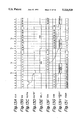
- FIGS. 12A through 12H are timing diagrams showing the operation of the circuit of FIG. 11;
- FIGS. 13A through 13I are timing diagrams showing a write operation of the device of FIG. 8;
- FIG. 14 is a block circuit diagram illustrating a second embodiment of the one-chip FIFO memory device according to the present invention.
- FIGS. 15A through 15E are timing diagrams showing the operation of the device of FIG. 14.
- reference numeral 1 designates an analog/digital (A/D) converter for converting an image analog data signal TV into a digital signal such as an 8-bit digital signal
- 2 designates a synchronization separating circuit for detecting a horizontal synchronization signal HS and a vertical synchronization signal VS, and the like.
- Reference numeral 3 designates a frame memory formed by an FIFO memory device for storing data of one screen.
- a write operation is performed by using a write address ADD W upon the frame memory 3
- a read operation is performed by using a read address ADD R upon the frame memory 3.
- the write address ADD W is incremented by receiving a clock signal CLK and is reset (cleared) by a write reset signal RSTW
- the read address ADD R is incremented by receiving the clock signal CLK and is reset (cleared) by a read reset signal RSTR.
- Both of the write reset signal RSTW and the read reset signal RSTR are generated by using the vertical synchronization signal VS, but the write reset signal RSTW is delayed by a delay circuit 4, compared with the read reset signal RSTR, thereby coinciding an effective time of a write operation with that of a read operation.
- Reference numerals 5 and 6 designates operation units for performing an image processing of the image data.
- the operation unit 5 calculates a brightness signal Y by adding previous image data to current image data
- the operation unit 6 calculates a color signal C by subtracting the current image data from the previous image data.
- reference numeral 7 designates an inverse matrix operation circuit for calculating red, green, and blue signals ER, EG, and EB which are converted, by D/A converters 8-1, 8-2, and 8-3 into analog signals, and are transmitted to a CRT 9.
- FIG. 2 which illustrates a part of the NTSC system's receiver
- a sub screen smaller than a main screen is introduced into the main screen.
- elements 10 through 13 are provided between the A/D converter 1 (the synchronization separating circuit 2) and the frame memory 3 (including the delay circuit 4).
- reference numeral 10 designates a frame memory 10 formed by an FIFO memory device, a delay circuit 11, a control circuit 12, and a selector 13.
- the control circuit 12 operates the selector 13 so that a sub screen defined by the frame memory 10 is introduced into the main screen.
- the frame memory 10 and the delay circuit 11 are similar to the frame memory 3 and the delay circuit 4, respectively, of FIG. 1. Therefore, also in the frame memory 10, an effective timing of a write reset signal RSTW is coincided with that of a read reset signal RSTR.
- Reference numeral 34 designates a 32-ary write counter which counts a clock signal CLK and is reset (cleared) by the write reset signal RSTW
- 35 designates a write address generating circuit which counts a carry-out signal of the 32-ary write counter 34.
- the write address generating circuit 35 is also cleared by the write reset signal RSTW. For example, the write address generating circuit 35 generates an 8-bit output.
- a JK flip-flop 36 is inverted by receiving each carry-out signal of the write counter 34, and as a result the selector 32 is inverted to alternatingly select the shift registers 33A and 33B.
- Reference numeral 40 designates a 32-ary read counter which counts the clock signal CLK and is reset (cleared) by the read reset signal RSTR
- 41 designates a write address generating circuit which counts a carry-out signal of the 32-ary read counter 40.
- the address generating 41 is also cleared by the write reset signal RSTR.
- the read address generating circuit 41 generates an 8-bit output.
- a JK flip-flop 42 is inverted by receiving each carry-out signal of the read counter 40, and as a result the selector is inverted to alternatingly select the shift registers 39A and 39B.
- Reference numeral 44' designates a delay circuit for delaying the read reset signal RST by four pulses of the clock signal CLK. As a result, the JK flip-flop 42 is also inverted by a delayed signal of the read reset signal RSTR.
- the delay circuit 44' includes a 4-ary counter 441', an inverter 442', an inverter 443', a register 444', and an AND circuit 445'. Note that the inverter 443', the register 444', and the AND circuit 445' as a whole form a differential circuit.
- the output SEL 1 of the JK flip-flop 36 is low ("0") as shown in FIG. 6D, and as a result, the selector 32 selects the shift register 33B.
- the write address generating circuit 35 is reset (cleared) to generate a write address 0, as shown in FIG. 6H. Note that the operation of the write address generating circuit 35 is delayed by four pulses of the clock signal CLK.
- the write counter 34 When 32 pixels of input image data D IN are written into the shift register 33A, the write counter 34 generates a carry-out signal, thereby inverting the output SEL 1 of the JK flip-flop 36, as shown in FIG. 6D. As a result, the selector 32 selects the shift register 33B, and therefore, input image data D IN is written into the shift register 33B, as shown in FIG. 6B. Also, at time t 3 , the previously stored input image data D IN in the shift register 33A is written into a portion of the memory cell array 31 indicated by address "0", as shown in FIG. 6G.
- the write counter 34 generates a carry-out signal and transmits it to the write address generating circuit 35.
- the write address ADD W of the write address generating circuit 35 is changed from "0" to "1", as shown in FIG. 6H, thereby enabling a write operation upon a portion of the memory cell array 31 indicated by address "1".
- the output SEL 2 of the JK flip-flop 42 is low ("0") as shown in FIG. 7C, and as a result, the selector 38 selects the shift register 39B.
- the output SEL 2 of the JK flip-flop 42 is inverted due to a delay circuit 44; as shown in FIG. 7C.
- the selector 38 selects the shift register 39A, and therefore, the image data of the shift register 39A is output as output image data D OUT as shown in FIG. 7G.
- a write reset signal RSTW is supplied to the one-chip FIFO memory device 3
- a write operation is promptly performed upon the shift register 33A or 33B, i.e., a write operation is carried out simultaneously with a write reset signal RSTW.
- a read reset signal RSTR is supplied to the one-chip FIFO memory device 3
- an image data D OUT is obtained at the output terminals thereof with a delay time such as a time corresponding to four pulses of the clock signal CLK.
- a read operation can be carried out after four pulses of the clock signal CLK are generated after the generation of a read reset signal RSTR, and thus an effective timing of the read reset signal RSTR is delayed, compared with that of the write reset signal RSTW.
- the delay circuit 4 of FIG. 1 or the delay circuit 11 of FIG. 2 is provided outside of the prior art one-chip FIFO memory device. Therefore, to manufacture the circuits of FIGS. 1 and 2, the delay circuits 4 and 10 must be designed to match the timings of the write and read reset signals with each other, which thereby increases the manufacturing cost.
- FIG. 8 which illustrates a first embodiment of the present invention
- a delay circuit 44 is added to the elements of FIG. 3.
- the delay circuit 44 is formed by a circuit as illustrated in FIG. 9 or 11.
- the delay circuit 44 includes four D flip-flops 441 through 444 connected in series. All of the D flip-flops are clocked by the clock signal CLK.
- the write reset signal RSTW is supplied to a data input of the first stage of the D flip-flops. As shown in FIGS. 10A through 10E, the write reset signal RSTW is delayed by 4, where , is a period of the clock signal CLK.
- the delay circuit 44 includes JK flip-flops 445 and 446, an AND circuit 447, an inverter 448, an inverter 449, a register 450, and an AND circuit 451.
- FIGS. 12A through 12H The operation of the delay circuit 44 of FIG. 11 is explained with reference to FIGS. 12A through 12H.
- the write reset signal is made low ("0") as shown in FIG. 12B
- the output A of JK flip-flop 445 is changed in response to the clock signal CLK of FIG. 12A, as shown in FIG. 12C, and as a result, the output B of the JK flip-flop 446 is changed in response to the clock signal CLK, as shown in FIG. 12E.
- the output D of the AND circuit 447 and the signal C thereof inverted by the inverter 448 are obtained as shown in FIGS. 12F and 12E.
- the output E of the register 450 is obtained as shown in FIG. 12G, and thus an output of the AND circuit 451, i.e., a delayed write reset signal RSTW' is obtained as shown in FIG. 12H.
- FIGS. 13A through 13I The write operation of the device of FIG. 8 is shown in FIGS. 13A through 13I.
- FIGS. 13A, 13B, 13D through 13I correspond to FIGS. 6A through 6H, respectively.
- the delayed write reset signal RSTW' is obtained by delaying the write reset signal RSTW by a time 4 ⁇ .
- a write operation upon the shift register 33A is initiated after a time 4 ⁇ has passed from the input of the write reset reset signal RSTW, and an output data D OUT is obtained at the output terminals after a time 4 ⁇ has passed from the input of the read reset signal RSTR. Therefore, if the read reset signal RSTR is the same as the write reset signal RSTW, an effective timing of the write reset signal RSTW coincides with that of the read reset signal RSTR.
- an RS flip-flop 45 is added to the elements of the device of FIG. 8. Namely, the output RSTW' of the delay circuit 44 is supplied to a reset input of the RS flip-flop 45, and a carry-out signal of the write address generating circuit 35 is supplied to a set input of the RS flip-flop 45.
- This RS flip-flop 45 generates a write enable signal WE0 and transmits it to the write decoder 37. If the write enable signal WE0 is high ("1"), the write decoder 37 is disabled so that a write operation is not carried out, and if the write enable signal WE0 is low (“0"), the write decoder 37 is enabled to carry out a write operation.
- This RS flip-flop 45 is used for displaying a stationary screen. Note, in the device of FIG. 11, the write reset signal RSTW (RSTW') is independent of the read reset signal RSTR.
- a stationary screen can be obtained without a special external terminal for the write enable signal WE. If such a special external terminal is provided, the same elements as the write counter 34 and the write address generating circuit 35 must be also externally provided, which increases the manufacturing cost.
- the delay circuit 44 is provided for the write reset signal RSTW, but if an effective timing of the write reset signal RSTW is delayed, compared with that of the read reset signal RSTR, such a delay circuit can be provided for the read reset signal RSTR.
Landscapes
- Engineering & Computer Science (AREA)
- Theoretical Computer Science (AREA)
- Microelectronics & Electronic Packaging (AREA)
- Physics & Mathematics (AREA)
- General Engineering & Computer Science (AREA)
- General Physics & Mathematics (AREA)
- Dram (AREA)
Abstract
Description
Claims (11)
Applications Claiming Priority (4)
| Application Number | Priority Date | Filing Date | Title |
|---|---|---|---|
| JP2-218611 | 1990-08-20 | ||
| JP2218611A JPH04102289A (en) | 1990-08-20 | 1990-08-20 | Fifo memory device |
| JP2218613A JPH04102291A (en) | 1990-08-20 | 1990-08-20 | Fifo memory device |
| JP2-218613 | 1990-08-20 |
Publications (1)
| Publication Number | Publication Date |
|---|---|
| US5220529A true US5220529A (en) | 1993-06-15 |
Family
ID=26522660
Family Applications (1)
| Application Number | Title | Priority Date | Filing Date |
|---|---|---|---|
| US07/747,047 Expired - Lifetime US5220529A (en) | 1990-08-20 | 1991-08-19 | One-chip first-in first-out memory device having matched write and read operations |
Country Status (1)
| Country | Link |
|---|---|
| US (1) | US5220529A (en) |
Cited By (21)
| Publication number | Priority date | Publication date | Assignee | Title |
|---|---|---|---|---|
| US5504913A (en) * | 1992-05-14 | 1996-04-02 | Apple Computer, Inc. | Queue memory with self-handling addressing and underflow |
| US5513145A (en) * | 1992-03-17 | 1996-04-30 | Fujitsu Limited | FIFO memory device capable of writing contiguous data into rows |
| US5594926A (en) * | 1993-07-19 | 1997-01-14 | Efar Microsystems, Inc. | Hard disk accelerating system for computer |
| US5596540A (en) * | 1993-10-20 | 1997-01-21 | Texas Instruments Incorporated | Serial to parallel and parallel to serial architecture for a RAM based FIFO memory |
| US5661418A (en) * | 1996-03-13 | 1997-08-26 | Cypress Semiconductor Corp. | Signal generation decoder circuit and method |
| US5712820A (en) * | 1995-11-17 | 1998-01-27 | Cypress Semiconductor Corporation | Multiple word width memory array clocking scheme |
| US5712992A (en) * | 1995-12-06 | 1998-01-27 | Cypress Semiconductor Corporation | State machine design for generating empty and full flags in an asynchronous FIFO |
| US5764967A (en) * | 1996-03-29 | 1998-06-09 | Cypress Semiconductor Corporation | Multiple frequency memory array clocking scheme for reading and writing multiple width digital words |
| US5809339A (en) * | 1995-12-06 | 1998-09-15 | Cypress Semiconductor Corp. | State machine design for generating half-full and half-empty flags in an asynchronous FIFO |
| US5815459A (en) * | 1995-11-28 | 1998-09-29 | Samsung Electronics, Co., Ltd. | Address decoding . . . semiconductor memory |
| US5852748A (en) * | 1995-12-29 | 1998-12-22 | Cypress Semiconductor Corp. | Programmable read-write word line equality signal generation for FIFOs |
| US5860160A (en) * | 1996-12-18 | 1999-01-12 | Cypress Semiconductor Corp. | High speed FIFO mark and retransmit scheme using latches and precharge |
| US5914897A (en) * | 1997-07-25 | 1999-06-22 | Mitsubishi Denki Kabushiki Kaisha | FIFO memory device having address detection portion |
| US5963056A (en) * | 1995-12-14 | 1999-10-05 | Cypress Semiconductor Corp. | Full and empty flag generator for synchronous FIFOs |
| US5994920A (en) * | 1995-12-14 | 1999-11-30 | Cypress Semiconductor Corp. | Half-full flag generator for synchronous FIFOs |
| US6091426A (en) * | 1995-04-07 | 2000-07-18 | Intel Corporation | Integrating data scaling and buffering functions to minimize memory requirement |
| US6115280A (en) * | 1994-11-01 | 2000-09-05 | Mitsubishi Denki Kabushiki Kaisha | Semiconductor memory capable of burst operation |
| US6191992B1 (en) * | 1998-01-21 | 2001-02-20 | Oki Electric Industry Co., Ltd | First-in-first-out storage device including synchronized full-state detention and empty-state detention |
| US6341096B1 (en) * | 1998-06-25 | 2002-01-22 | Seiko Epson Corporation | Semiconductor memory device |
| US6510486B1 (en) | 1996-03-25 | 2003-01-21 | Cypress Semiconductor Corp. | Clocking scheme for independently reading and writing multiple width words from a memory array |
| US6633966B1 (en) * | 1998-06-16 | 2003-10-14 | Mitsubishi Denki Kabushiki Kaisha | FIFO memory having reduced scale |
-
1991
- 1991-08-19 US US07/747,047 patent/US5220529A/en not_active Expired - Lifetime
Non-Patent Citations (2)
| Title |
|---|
| Texas Instruments Catalog: 1M Bit Field Memory TMS4C1050, May, 1987, pp. 2 37 2 48. * |
| Texas Instruments Catalog: 1M Bit Field Memory TMS4C1050, May, 1987, pp. 2-37-2-48. |
Cited By (28)
| Publication number | Priority date | Publication date | Assignee | Title |
|---|---|---|---|---|
| US5513145A (en) * | 1992-03-17 | 1996-04-30 | Fujitsu Limited | FIFO memory device capable of writing contiguous data into rows |
| US5504913A (en) * | 1992-05-14 | 1996-04-02 | Apple Computer, Inc. | Queue memory with self-handling addressing and underflow |
| US5594926A (en) * | 1993-07-19 | 1997-01-14 | Efar Microsystems, Inc. | Hard disk accelerating system for computer |
| US5596540A (en) * | 1993-10-20 | 1997-01-21 | Texas Instruments Incorporated | Serial to parallel and parallel to serial architecture for a RAM based FIFO memory |
| US5602780A (en) * | 1993-10-20 | 1997-02-11 | Texas Instruments Incorporated | Serial to parallel and parallel to serial architecture for a RAM based FIFO memory |
| US6181612B1 (en) | 1994-11-01 | 2001-01-30 | Mitsubishi Denki Kabushiki Kaisha | Semiconductor memory capable of burst operation |
| US6115280A (en) * | 1994-11-01 | 2000-09-05 | Mitsubishi Denki Kabushiki Kaisha | Semiconductor memory capable of burst operation |
| US6091426A (en) * | 1995-04-07 | 2000-07-18 | Intel Corporation | Integrating data scaling and buffering functions to minimize memory requirement |
| US5930176A (en) * | 1995-11-17 | 1999-07-27 | Cypress Semiconductor Corp. | Multiple word width memory array clocking scheme |
| US5712820A (en) * | 1995-11-17 | 1998-01-27 | Cypress Semiconductor Corporation | Multiple word width memory array clocking scheme |
| US5815459A (en) * | 1995-11-28 | 1998-09-29 | Samsung Electronics, Co., Ltd. | Address decoding . . . semiconductor memory |
| US5991834A (en) * | 1995-12-06 | 1999-11-23 | Cypress Semiconductor Corp. | State machine design for generating half-full and half-empty flags in an asynchronous FIFO |
| US5809339A (en) * | 1995-12-06 | 1998-09-15 | Cypress Semiconductor Corp. | State machine design for generating half-full and half-empty flags in an asynchronous FIFO |
| US5712992A (en) * | 1995-12-06 | 1998-01-27 | Cypress Semiconductor Corporation | State machine design for generating empty and full flags in an asynchronous FIFO |
| US6016403A (en) * | 1995-12-06 | 2000-01-18 | Cypress Semiconductor Corp. | State machine design for generating empty and full flags in an asynchronous FIFO |
| US5963056A (en) * | 1995-12-14 | 1999-10-05 | Cypress Semiconductor Corp. | Full and empty flag generator for synchronous FIFOs |
| US5994920A (en) * | 1995-12-14 | 1999-11-30 | Cypress Semiconductor Corp. | Half-full flag generator for synchronous FIFOs |
| US5852748A (en) * | 1995-12-29 | 1998-12-22 | Cypress Semiconductor Corp. | Programmable read-write word line equality signal generation for FIFOs |
| US5955897A (en) * | 1996-03-13 | 1999-09-21 | Cypress Semiconductor Corp. | Signal generation decoder circuit and method |
| US5661418A (en) * | 1996-03-13 | 1997-08-26 | Cypress Semiconductor Corp. | Signal generation decoder circuit and method |
| US6510486B1 (en) | 1996-03-25 | 2003-01-21 | Cypress Semiconductor Corp. | Clocking scheme for independently reading and writing multiple width words from a memory array |
| US5764967A (en) * | 1996-03-29 | 1998-06-09 | Cypress Semiconductor Corporation | Multiple frequency memory array clocking scheme for reading and writing multiple width digital words |
| US5860160A (en) * | 1996-12-18 | 1999-01-12 | Cypress Semiconductor Corp. | High speed FIFO mark and retransmit scheme using latches and precharge |
| US5914897A (en) * | 1997-07-25 | 1999-06-22 | Mitsubishi Denki Kabushiki Kaisha | FIFO memory device having address detection portion |
| DE19804384B4 (en) * | 1997-07-25 | 2010-12-09 | Mitsubishi Denki K.K. | Semiconductor memory device |
| US6191992B1 (en) * | 1998-01-21 | 2001-02-20 | Oki Electric Industry Co., Ltd | First-in-first-out storage device including synchronized full-state detention and empty-state detention |
| US6633966B1 (en) * | 1998-06-16 | 2003-10-14 | Mitsubishi Denki Kabushiki Kaisha | FIFO memory having reduced scale |
| US6341096B1 (en) * | 1998-06-25 | 2002-01-22 | Seiko Epson Corporation | Semiconductor memory device |
Similar Documents
| Publication | Publication Date | Title |
|---|---|---|
| US5220529A (en) | One-chip first-in first-out memory device having matched write and read operations | |
| US5640502A (en) | Bit-mapped on-screen-display device for a television receiver | |
| CA1154147A (en) | Method for a compatible increase in resolution in television systems | |
| US4864402A (en) | Video memory | |
| US4620222A (en) | Digital color TV camera | |
| CA1268248A (en) | Television picture display device | |
| JPS61117989A (en) | Television receiver | |
| US5444497A (en) | Apparatus and method of transferring video data of a moving picture | |
| US5534936A (en) | Apparatus for reducing flickers of encoder when digitally converting video signals from non-interlaced to interlaced format | |
| US4471377A (en) | Color information display apparatus | |
| KR950009698B1 (en) | NTSC / HDTVM Dual Receiver Line Tripler | |
| US4694325A (en) | Interface circuit contained in a color-television receiver and serving to connect a home computer | |
| US6377199B1 (en) | Signal processor system with noise suppression | |
| JPS59114581A (en) | display device | |
| KR940001838B1 (en) | Video data split circuit | |
| SU1665391A1 (en) | System for tv picture input to a computer | |
| JPS637593A (en) | Frequency converting circuit | |
| JP3107555B2 (en) | Data processing device | |
| US4533953A (en) | Signal analyzing circuit for a periodically occurring signal | |
| JPH02121566A (en) | Picture signal processor | |
| JP3068215B2 (en) | Semiconductor memory device | |
| JPS6075871A (en) | Improved character coloring circuit | |
| JPS59126377A (en) | High speed image pickup device | |
| JP2001346151A (en) | Video signal processing unit | |
| Gillies et al. | VLSI realisations for picture in picture and flicker free television display |
Legal Events
| Date | Code | Title | Description |
|---|---|---|---|
| AS | Assignment |
Owner name: FUJITSU LIMITED, JAPAN Free format text: ASSIGNMENT OF ASSIGNORS INTEREST.;ASSIGNORS:KOHIYAMA, KIYOSHI;TAKAHASHI, HIDENAGA;OTOBE, YUKIO;REEL/FRAME:005815/0177 Effective date: 19910814 |
|
| FEPP | Fee payment procedure |
Free format text: PAYER NUMBER DE-ASSIGNED (ORIGINAL EVENT CODE: RMPN); ENTITY STATUS OF PATENT OWNER: LARGE ENTITY Free format text: PAYOR NUMBER ASSIGNED (ORIGINAL EVENT CODE: ASPN); ENTITY STATUS OF PATENT OWNER: LARGE ENTITY |
|
| FEPP | Fee payment procedure |
Free format text: PAYOR NUMBER ASSIGNED (ORIGINAL EVENT CODE: ASPN); ENTITY STATUS OF PATENT OWNER: LARGE ENTITY |
|
| STCF | Information on status: patent grant |
Free format text: PATENTED CASE |
|
| FPAY | Fee payment |
Year of fee payment: 4 |
|
| FPAY | Fee payment |
Year of fee payment: 8 |
|
| FPAY | Fee payment |
Year of fee payment: 12 |
|
| AS | Assignment |
Owner name: FUJITSU MICROELECTRONICS LIMITED, JAPAN Free format text: ASSIGNMENT OF ASSIGNORS INTEREST;ASSIGNOR:FUJITSU LIMITED;REEL/FRAME:021998/0645 Effective date: 20081104 Owner name: FUJITSU MICROELECTRONICS LIMITED,JAPAN Free format text: ASSIGNMENT OF ASSIGNORS INTEREST;ASSIGNOR:FUJITSU LIMITED;REEL/FRAME:021998/0645 Effective date: 20081104 |
|
| AS | Assignment |
Owner name: FUJITSU SEMICONDUCTOR LIMITED, JAPAN Free format text: CHANGE OF NAME;ASSIGNOR:FUJITSU MICROELECTRONICS LIMITED;REEL/FRAME:024982/0245 Effective date: 20100401 |