US521950A - Chaeles victor divan - Google Patents
Chaeles victor divan Download PDFInfo
- Publication number
- US521950A US521950A US521950DA US521950A US 521950 A US521950 A US 521950A US 521950D A US521950D A US 521950DA US 521950 A US521950 A US 521950A
- Authority
- US
- United States
- Prior art keywords
- cylinder
- divan
- victor
- chaeles
- partitions
- Prior art date
- Legal status (The legal status is an assumption and is not a legal conclusion. Google has not performed a legal analysis and makes no representation as to the accuracy of the status listed.)
- Expired - Lifetime
Links
- 238000005192 partition Methods 0.000 description 14
- 238000012856 packing Methods 0.000 description 4
- 229910001018 Cast iron Inorganic materials 0.000 description 3
- 238000012986 modification Methods 0.000 description 2
- 230000004048 modification Effects 0.000 description 2
- 230000000694 effects Effects 0.000 description 1
- 235000013531 gin Nutrition 0.000 description 1
- 239000002184 metal Substances 0.000 description 1
- 229910052751 metal Inorganic materials 0.000 description 1
- 210000000056 organ Anatomy 0.000 description 1
- 230000000149 penetrating effect Effects 0.000 description 1
- 229920000136 polysorbate Polymers 0.000 description 1
- 230000001105 regulatory effect Effects 0.000 description 1
- 238000004326 stimulated echo acquisition mode for imaging Methods 0.000 description 1
Images
Classifications
-
- F—MECHANICAL ENGINEERING; LIGHTING; HEATING; WEAPONS; BLASTING
- F01—MACHINES OR ENGINES IN GENERAL; ENGINE PLANTS IN GENERAL; STEAM ENGINES
- F01C—ROTARY-PISTON OR OSCILLATING-PISTON MACHINES OR ENGINES
- F01C21/00—Component parts, details or accessories not provided for in groups F01C1/00 - F01C20/00
- F01C21/08—Rotary pistons
- F01C21/0809—Construction of vanes or vane holders
- F01C21/0818—Vane tracking; control therefor
- F01C21/0854—Vane tracking; control therefor by fluid means
- F01C21/0863—Vane tracking; control therefor by fluid means the fluid being the working fluid
Definitions
- V I -My invention includesja cylinder, a'disk or disks arranged .ec'centrically”therein, sliding" part tions n thedisk arranged to bear on the" 1nter1or of the cylinder and packi-ngs carried" in the ends of-said sliding partitions adapted to have movementtoi'maintainafirm hearing onthe cylinder..': The packings are disposedinsucha manner that the steam presses the same directly without any intermediate devlce, to the interior wall of v the cylinder.
- the posltion of the motive disk, as far as the cylinder, is concerned is regulated by stuffing boxes or packings consisting of two. partsv which can be pressed more or less into the bearmgs of the shaft of the disk in order to take up wear.
- the motor can be disposed so as to work in both directions and canconsist either .motor, following the line 3-4 of Figs. 1 and 2.
- My motor consists of an ordinary cylinder A divided in two unequal parts (a, a) by means of a partition Lfixed therein.
- the partitions can be of similar forms as in Fig. 3, or they can engage by means of a groove and a tongue as represented in the modification shown by Fig. 4.
- the diameter of the disks B B is slightly superior to the radius of the motive cylinder, its proportion to the diameter of the latter being on an aver* age from 0.60 to 0.70.
- the partitions 0 are arranged 'to slide easily in the two notchesof the disks and at their free extremities they carry metallic packings K having theshape of spatulas made of anti-friction metal or of cast-iron and intended to insure a tightjoint vbetween the cylinder and partition and be-' tween the partitions and the parts L.
- One of the surfaces of these spatulas K which rests against the interior wall of the motive cylinder has exactly the curvature of the wall of the latter, so that, notwithstanding the obliquity of the motive partitions in the cylinder, the surface will always remain. normal in regard to the radius ofthe latter and will constantly always fit perfectly the curved surface of the cylinder in all its positions and therefore assure the tightness of the joint.
- the motive cylinder or cylinders are thus divided into two separated compartments one of which is in constant communication with the orifice through which the steam comes in and the other with the exhaust.
- the circulation of the steam is eltected in the following manner in the case of the com pound motor shown in the drawings; it'would be analogous for a simple or a multiple eitpansion motor.
- the inlet of the steam is through the orifice E which communicates with the double envelope 0 formed by the walls 1; from there it passes through the admission orifice P into the cylinder (a) where it produces its effect by carrying along the partitions CO, and consequently the disk B and themotive shaft M.
Landscapes
- Engineering & Computer Science (AREA)
- Mechanical Engineering (AREA)
- General Engineering & Computer Science (AREA)
- Paper (AREA)
Description
.c 6 0v h S w e e h S 2 S Lm IG PN IE NW A Vm IS D m T 0 GR (No Model.)
1%. 521,950. Patented June 26, 1894.
5 ITZZJCTL (No Model.) E 2 SheetsSheet 2.
g G. V. DIVAN, FILS.
V ROTARY STEAM ENGINE. v
No. 521,950. Patented June 26,1894.-
WWI
I 71L? .dblorrzgys I V YHE GHAFHING QDMFANY tional plan view of the same along the shaft To aZ Z 'my-cbncam. i
. Be it known thatI, CHARLES VIcTo DIVAN, F115, a citizen of theFrench-Republic, resid-- "'U FTED @TATEASF PATENT Q QE;
' CHARLES 'vrcToRfmvAN, FI LS,;OF\ST. NAzAIRn-FRANoE.
ROTARY STEAM-ENGINE.
SEfECIFIOATIONfQrmingpaIt of Letters Patent' No. 521,950, dated'J'une 2c, 1894. V Applicationfiled January 12,1894. SerialN o- $96358 (No model.) Patented in France June 3, 1893, No. 280,561-- ing at St. Njazaire, inv the Departmentof the Lorre-Infrleure, France, have-invented certam new and useful Improveme'nts'in Rotary Steam-En gines, (for which Letters Patent were granted in, France on the 3d of June,'1893, "No.- 230,561,).of which thefollowingisa specification: V I -My invention includesja cylinder, a'disk or disks arranged .ec'centrically"therein, sliding" part tions n thedisk arranged to bear on the" 1nter1or of the cylinder and packi-ngs carried" in the ends of-said sliding partitions adapted to have movementtoi'maintainafirm hearing onthe cylinder..': The packings are disposedinsucha manner that the steam presses the same directly without any intermediate devlce, to the interior wall of v the cylinder. The posltion of the motive disk, as far as the cylinder, is concerned is regulated by stuffing boxes or packings consisting of two. partsv which can be pressed more or less into the bearmgs of the shaft of the disk in order to take up wear. The motor can be disposed so as to work in both directions and canconsist either .motor, following the line 3-4 of Figs. 1 and 2.
of one cylinder or of two cylinders of unequal sizeand having coupled shafts. In that case, the steam thatescapes from the first cylinder will act in the same manner in the second'or expansion cylinder before escaping to the condenser or to the free air.
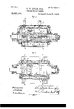
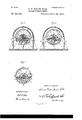
In the drawin'gsz-Figurel, is a longitudinal section of the rotary motor; Fig. 2, a, secof the cylinder; Fig. 3, a transverse sectional View of the'same, on the line 12 of Figs; 1 and 2; Fig. 4, a modification of the same View; Fig. 5, a transverse sectional view of the same The same reference letters and numerals indicate thesame parts in the different figures. f
My motor consists of an ordinary cylinder A divided in two unequal parts (a, a) by means of a partition Lfixed therein. The
I two extremities of the cylinder are provided with covers D through which the motive shaft M passes eccentrically and through stuffing boxes orother-convenient' packing. J Upon this'shaft are fixed two disks B B. eccentrically as far as the cylinder is'concerned and thelowerparts of which are tangent to the" same. The motive shaft'Mpasses also through the partition Lbeing. held' in position and guided therein b'yabo'ss'(m)." 'The'two disks B B are of cast-iron and areeach respectively as-long asthedistance between the opposite covers D and the dividing partition L; "they each carry two movable partitions G, O
which are'independent and made of cast iron orcast steeland upon which the pressure of the steam works; these part-itions'can slide the one over the other in the direction of their width ina groove made in the disk. The relative motion of those two partitions in regard the one to the other is caused by the ac tion of the steam arriving through the introduction pipe G and penetrating through the pipe (g) up to a space (9) that exists between.
the same, the result of which is a sliding ef fect, of the partitions outwardly, which'makes the free extremities of the partitions rest against the interior wall of the cylinder at all times. The partitionscan be of similar forms as in Fig. 3, or they can engage by means of a groove and a tongue as represented in the modification shown by Fig. 4. The diameter of the disks B B is slightly superior to the radius of the motive cylinder, its proportion to the diameter of the latter being on an aver* age from 0.60 to 0.70. The partitions 0 are arranged 'to slide easily in the two notchesof the disks and at their free extremities they carry metallic packings K having theshape of spatulas made of anti-friction metal or of cast-iron and intended to insure a tightjoint vbetween the cylinder and partition and be-' tween the partitions and the parts L. One of the surfaces of these spatulas K which rests against the interior wall of the motive cylinder has exactly the curvature of the wall of the latter, so that, notwithstanding the obliquity of the motive partitions in the cylinder, the surface will always remain. normal in regard to the radius ofthe latter and will constantly always fit perfectly the curved surface of the cylinder in all its positions and therefore assure the tightness of the joint.
The motive cylinder or cylinders are thus divided into two separated compartments one of which is in constant communication with the orifice through which the steam comes in and the other with the exhaust.
The circulation of the steam is eltected in the following manner in the case of the com pound motor shown in the drawings; it'would be analogous for a simple or a multiple eitpansion motor. The inlet of the steam is through the orifice E which communicates with the double envelope 0 formed by the walls 1; from there it passes through the admission orifice P into the cylinder (a) where it produces its effect by carrying along the partitions CO, and consequently the disk B and themotive shaft M. After havingthus efiected itsoperation it escapes through the orifice R, from where it passes through the double envelopeO formed by the walls 2, and the admission orifice S into the large expansion cylinder at" in which it acts in the same manner, and escapes through the orifice T and from there passing through the double envelope 0" formed by the walls 3 it reaches the exhaust orifice F whichcan be placed at the same side of the inlet E or in any other suitable place. a p i The other accessory organs of the machine are the same as those generally used; therefore I willnot describe them here.
CHARLES VICTOR DIVAN,F1Ls: Witnesses:
M. SUPPLE, lI. VAN ()LDENNEEL.
Publications (1)
| Publication Number | Publication Date |
|---|---|
| US521950A true US521950A (en) | 1894-06-26 |
Family
ID=2590747
Family Applications (1)
| Application Number | Title | Priority Date | Filing Date |
|---|---|---|---|
| US521950D Expired - Lifetime US521950A (en) | Chaeles victor divan |
Country Status (1)
| Country | Link |
|---|---|
| US (1) | US521950A (en) |
-
0
- US US521950D patent/US521950A/en not_active Expired - Lifetime
Similar Documents
| Publication | Publication Date | Title |
|---|---|---|
| US521950A (en) | Chaeles victor divan | |
| US722480A (en) | Rotary engine. | |
| GB333339A (en) | Improvements relating to packings for rotary or reciprocatory shafts or rods | |
| US625731A (en) | Rotary engine | |
| US661061A (en) | Steam-engine cylinder. | |
| US997895A (en) | Rotary engine. | |
| US1494169A (en) | Combined bearing and packing mechanism | |
| US844824A (en) | Rotary engine. | |
| US230907A (en) | thibalt | |
| US802843A (en) | Rotary engine. | |
| US688571A (en) | Packing for pistons. | |
| US269991A (en) | Benjamin t | |
| US718725A (en) | Multiple-expansion rotary engine. | |
| US774867A (en) | Motor. | |
| US510116A (en) | Valve for steam-engines | |
| US599922A (en) | Balanced valve | |
| US294304A (en) | Revolving-cylinder engine | |
| US364374A (en) | Half to daniel p | |
| US733852A (en) | Eccentric. | |
| US269300A (en) | Eotaet engine | |
| US773649A (en) | Rotary engine. | |
| US1234953A (en) | Journal-bearing. | |
| US518812A (en) | Rotary engine | |
| US411563A (en) | Packing | |
| US419062A (en) | Alfred n |