US5219088A - Fixing ring for securing a closure to a container - Google Patents
Fixing ring for securing a closure to a container Download PDFInfo
- Publication number
- US5219088A US5219088A US07/877,922 US87792292A US5219088A US 5219088 A US5219088 A US 5219088A US 87792292 A US87792292 A US 87792292A US 5219088 A US5219088 A US 5219088A
- Authority
- US
- United States
- Prior art keywords
- ring
- lever
- wing
- closure
- upper wing
- Prior art date
- Legal status (The legal status is an assumption and is not a legal conclusion. Google has not performed a legal analysis and makes no representation as to the accuracy of the status listed.)
- Expired - Fee Related
Links
Images

Classifications
-
- B—PERFORMING OPERATIONS; TRANSPORTING
- B65—CONVEYING; PACKING; STORING; HANDLING THIN OR FILAMENTARY MATERIAL
- B65D—CONTAINERS FOR STORAGE OR TRANSPORT OF ARTICLES OR MATERIALS, e.g. BAGS, BARRELS, BOTTLES, BOXES, CANS, CARTONS, CRATES, DRUMS, JARS, TANKS, HOPPERS, FORWARDING CONTAINERS; ACCESSORIES, CLOSURES, OR FITTINGS THEREFOR; PACKAGING ELEMENTS; PACKAGES
- B65D45/00—Clamping or other pressure-applying devices for securing or retaining closure members
- B65D45/32—Clamping or other pressure-applying devices for securing or retaining closure members for applying radial or radial and axial pressure, e.g. contractible bands encircling closure member
- B65D45/34—Clamping or other pressure-applying devices for securing or retaining closure members for applying radial or radial and axial pressure, e.g. contractible bands encircling closure member lever-operated
- B65D45/345—Lever-operated contractible or expansible band, the lever moving in the plane of the band
-
- Y—GENERAL TAGGING OF NEW TECHNOLOGICAL DEVELOPMENTS; GENERAL TAGGING OF CROSS-SECTIONAL TECHNOLOGIES SPANNING OVER SEVERAL SECTIONS OF THE IPC; TECHNICAL SUBJECTS COVERED BY FORMER USPC CROSS-REFERENCE ART COLLECTIONS [XRACs] AND DIGESTS
- Y10—TECHNICAL SUBJECTS COVERED BY FORMER USPC
- Y10T—TECHNICAL SUBJECTS COVERED BY FORMER US CLASSIFICATION
- Y10T292/00—Closure fasteners
- Y10T292/20—Clamps
- Y10T292/205—Ring
- Y10T292/212—With expanding or contracting means
- Y10T292/216—Toggle lever
Definitions
- the present invention relates to a fixing ring for securing a closure to a container.
- Ring-like devices which substantially have a split-ring body on the outside of which a lever is pivoted; said lever is articulated, in a median portion, to a traction element which is connected to the other end of the split ring, so that when the lever is moved toward the ring-like body it secures it and fixes the closure to the container.
- this embodiment has the drawback according to which the bulk of the lever, in closure position, protrudes with respect to the outer peripheral region of the drum, thereby increasing the chance of occurrence of impacts which can damage the lever and consequently make the coupling of the closure unstable.
- Another problem is furthermore constituted by the fact that there are difficulties in applying so-called guarantee seals, which are in practice constituted by laminae which insert in a snap-together manner in a slot defined on the lever and in a corresponding slot defined on the closure.
- the aim of the present invention is to eliminate the problems described above by providing a fixing ring for securing a closure to a container, which allows not to have bulks outside the ring-like body and furthermore which leaves the central portion of the closure free as well, consequently allowing the easy stacking of the various containers.
- a particular object of the invention is to provide a fixing ring which allows to apply the guarantee seal or safety seal without having to resort to the subsequent application of protective barriers in order to prevent fraudulent extraction.
- Another object of the present invention is to provide a fixing ring which, by virtue of its peculiar constructive characteristics, is capable of giving the greatest assurances of reliability and safety in use.
- Not least object of the present invention is to provide a fixing ring for securing a closure to a container which can be easily obtained starting from commonly commercially available elements and materials and which is furthermore competitive from a merely economical point of view.
- a fixing ring for securing a closure to a container characterized in that it comprises a ring-like body which is open at one point and can engage the peripheral edge of a closure and the mouth of a container, a lever being pivoted to one end of said ring-like body, said lever extending toward the region delimited by said ring-like body, the end of a traction element being articulated to a median portion of said lever, said traction element being articulated to the other end of said ring-like body, said lever, in closure position, being at least partially superimposed on said ring-like body.
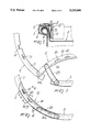
- FIG. 1 is a schematic perspective view of the fixing ring in open position
- FIG. 2 is a schematic view of the fixing ring applied to a container
- FIG. 3 is a plan view of a portion of the ring-like body in open position
- FIG. 4 is a view of the ring-like body in closure position
- FIG. 5 is a sectional view, taken along the plane V--V of FIG. 4;
- FIG. 6 is a sectional view, taken along the plane VI--VI of FIG. 4, with the blocking element unfolded;
- FIG. 7 is a sectional view, similar to FIG. 6, with the blocking element folded.
- the fixing ring for securing a closure to a container which is generally designated by the reference numeral 1, comprises a ring-like body 2 which is openable at one point.
- the transverse cross-section of the ring-like body is L-shaped, with an upper wing 3.
- a peripheral wing 6 is connected to the upper wing and can be already folded inwardly or may be arranged substantially perpendicular to the upper wing 3 and be folded inwardly after the ring-like body, already closed onto the closure 8, has been fixed to the container 9 (FIG. 5).
- the cross-section is enlarged (FIGS. 3 and 4), so as to facilitate the overlap of the two ends in the closed position.
- a lever 10 is pivoted at one end of the open ring-like body, extends (in an open position thereof) toward the inside of the region delimited by said ring-like body, and has an arc-like shape with the same radius of curvature as said ring-like body.
- the transverse cross-section of the lever is shaped like a right-angled L, with an inner wing 11 arranged substantially perpendicular to an upper edge 12, which is provided with a protruding ridge 14, which is interrupted at the zone thereof at which a bridge-like traction element 20 is pivoted.
- a curved protruding ridge 14a is also provided at the hinge zone of the lever for reinforcement thereof.
- the traction element 20 is articulated to a median portion of the lever 10 and is articulated, at its other end, to the other end of the ring-like body.
- a slot 30 is furthermore provided on the upper edge 12 of the lever 10 and can be arranged in alignment with a lower slot 31 defined on the ring-like body which allows to insert a guarantee seal or a safety seal, designated by 35, which has the function of indicating that the lever has been opened.
- the lever 10 can also be provided with a blocking slot 40 in which a blocking element 41 can lockingly engage; said blocking element is advantageously obtained from a bendable cut portion of the upper wing 3 of the ring-like body 2 itself, as seen in FIGS. 6 and 7, and thus such blocking element 41 acts as a locking mechanism which helps to avoid accidental openings of the seal 35.
- the inner wing 11 acts as protection element for the seal, preventing its fraudulent removal without breaking it.
- the lever When the lever is in its closure position, it practically overlaps the ring-like body, so that bulks toward the outside or toward the inside of said body are not created, thus allowing to stack a plurality of containers or drums on top of one another.
- a fixing ring is provided which can be applied to a drum, during its first application, so that its outer wing can be folded in order to close the closure on the drum or possibly with the outer wing already folded, so as to correctly fix the closure to the container.
- An important aspect of the invention is constituted by the fact that the lever does not create inward or outward bulks and that the guarantee seal is protected directly by the inner wing of the lever, so that its fraudulent removal is not possible, without having to perform the further application of barriers or the like.
- the materials employed may be any according to the requirements.
Abstract
The fixing ring for securing a closure to a container includes: a ring-like body which is open at one point and which can engage the peripheral edge of a closure and the mouth of a container; a lever which is pivoted to one end of the ring-like body and which extends toward the region delimited by the ring-like body itself; and a traction element having one end articulated to the median portion of the lever and another end articulated to the other end of the ring-like body, and the lever which, in its closure position, at least partially overlaps the ring-like body.
Description
The present invention relates to a fixing ring for securing a closure to a container.
As is known, in many industrial fields and in particular in the case of drums, it is necessary to be able to sealingly apply a closure to the mouth of a container in order to close it.
Ring-like devices are already known which substantially have a split-ring body on the outside of which a lever is pivoted; said lever is articulated, in a median portion, to a traction element which is connected to the other end of the split ring, so that when the lever is moved toward the ring-like body it secures it and fixes the closure to the container.
However, this embodiment has the drawback according to which the bulk of the lever, in closure position, protrudes with respect to the outer peripheral region of the drum, thereby increasing the chance of occurrence of impacts which can damage the lever and consequently make the coupling of the closure unstable.
Another problem is furthermore constituted by the fact that there are difficulties in applying so-called guarantee seals, which are in practice constituted by laminae which insert in a snap-together manner in a slot defined on the lever and in a corresponding slot defined on the closure.
Since the lever is on the outside of the ring-like body, it is necessary to provide barriers which prevent the fraudulent extraction of the lamina from its seat.
On the other hand, it is known to use ring-like closure bodies which do not have an external bulk for the closure lever but instead have a relatively large body which is accommodated within the space delimited by the ring-like body, so that it is practically impossible to stack a plurality of containers. These closures additionally have considerable constructive complexities.
The aim of the present invention is to eliminate the problems described above by providing a fixing ring for securing a closure to a container, which allows not to have bulks outside the ring-like body and furthermore which leaves the central portion of the closure free as well, consequently allowing the easy stacking of the various containers.
Within the scope of the above aim, a particular object of the invention is to provide a fixing ring which allows to apply the guarantee seal or safety seal without having to resort to the subsequent application of protective barriers in order to prevent fraudulent extraction.
Another object of the present invention is to provide a fixing ring which, by virtue of its peculiar constructive characteristics, is capable of giving the greatest assurances of reliability and safety in use.
Not least object of the present invention is to provide a fixing ring for securing a closure to a container which can be easily obtained starting from commonly commercially available elements and materials and which is furthermore competitive from a merely economical point of view.
This aim, these objects and others which will become apparent hereinafter are achieved by a fixing ring for securing a closure to a container, according to the invention, characterized in that it comprises a ring-like body which is open at one point and can engage the peripheral edge of a closure and the mouth of a container, a lever being pivoted to one end of said ring-like body, said lever extending toward the region delimited by said ring-like body, the end of a traction element being articulated to a median portion of said lever, said traction element being articulated to the other end of said ring-like body, said lever, in closure position, being at least partially superimposed on said ring-like body.
Further characteristics and advantages of the present invention will become apparent from the detailed description of a fixing ring for securing a closure to a container, illustrated only by way of non-limitative example in the accompanying drawings, wherein:
FIG. 1 is a schematic perspective view of the fixing ring in open position;
FIG. 2 is a schematic view of the fixing ring applied to a container;
FIG. 3 is a plan view of a portion of the ring-like body in open position;
FIG. 4 is a view of the ring-like body in closure position;
FIG. 5 is a sectional view, taken along the plane V--V of FIG. 4;
FIG. 6 is a sectional view, taken along the plane VI--VI of FIG. 4, with the blocking element unfolded;
FIG. 7 is a sectional view, similar to FIG. 6, with the blocking element folded.
With reference to the above figures, the fixing ring for securing a closure to a container, which is generally designated by the reference numeral 1, comprises a ring-like body 2 which is openable at one point.
The transverse cross-section of the ring-like body is L-shaped, with an upper wing 3.
A peripheral wing 6 is connected to the upper wing and can be already folded inwardly or may be arranged substantially perpendicular to the upper wing 3 and be folded inwardly after the ring-like body, already closed onto the closure 8, has been fixed to the container 9 (FIG. 5).
Furthermore, at one end of the ring-like body, the cross-section is enlarged (FIGS. 3 and 4), so as to facilitate the overlap of the two ends in the closed position.
A lever 10 is pivoted at one end of the open ring-like body, extends (in an open position thereof) toward the inside of the region delimited by said ring-like body, and has an arc-like shape with the same radius of curvature as said ring-like body.
The transverse cross-section of the lever is shaped like a right-angled L, with an inner wing 11 arranged substantially perpendicular to an upper edge 12, which is provided with a protruding ridge 14, which is interrupted at the zone thereof at which a bridge-like traction element 20 is pivoted. A curved protruding ridge 14a is also provided at the hinge zone of the lever for reinforcement thereof.
The traction element 20 is articulated to a median portion of the lever 10 and is articulated, at its other end, to the other end of the ring-like body.
A slot 30 is furthermore provided on the upper edge 12 of the lever 10 and can be arranged in alignment with a lower slot 31 defined on the ring-like body which allows to insert a guarantee seal or a safety seal, designated by 35, which has the function of indicating that the lever has been opened. The lever 10 can also be provided with a blocking slot 40 in which a blocking element 41 can lockingly engage; said blocking element is advantageously obtained from a bendable cut portion of the upper wing 3 of the ring-like body 2 itself, as seen in FIGS. 6 and 7, and thus such blocking element 41 acts as a locking mechanism which helps to avoid accidental openings of the seal 35.
With this arrangement, the inner wing 11 acts as protection element for the seal, preventing its fraudulent removal without breaking it.
When the lever is in its closure position, it practically overlaps the ring-like body, so that bulks toward the outside or toward the inside of said body are not created, thus allowing to stack a plurality of containers or drums on top of one another.
From what has been described above it can thus be seen that the invention achieves the intended aim and objects, and in particular the fact is stressed that a fixing ring is provided which can be applied to a drum, during its first application, so that its outer wing can be folded in order to close the closure on the drum or possibly with the outer wing already folded, so as to correctly fix the closure to the container.
An important aspect of the invention is constituted by the fact that the lever does not create inward or outward bulks and that the guarantee seal is protected directly by the inner wing of the lever, so that its fraudulent removal is not possible, without having to perform the further application of barriers or the like.
In practice, the materials employed, so long as they are compatible with the specific use, as well as the contingent shapes and dimensions, may be any according to the requirements.
Claims (6)
1. A fixing ring for securing a closure to a container, comprising:
a ring-like body which is open at one point and which is engageable with a peripheral edge of the closure and a mouth of the container, said ring-like body having a substantially L-shaped transverse cross-section with an upper wing and an outer wing which extends substantially perpendicularly to the upper wing, the upper wing having a substantially circular configuration which delimits an inner circular region;
a lever being pivotally connected to a first end of said ring-like body, said lever extending, in an unlatched position thereof, toward the inner circular region delimited by the upper wing of said ring-like body; and
a traction element having one end pivotally connected to a median portion of said lever and another end pivotally connected to a second end of said ring-like body;
said lever having a transverse cross-section which is substantially shaped like a right-angled L with an inner wing which extends substantially perpendicularly to an upper edge, said lever extending along a curved shape whose radius of curvature is substantially equal to a radius of curvature of said ring-like body, said lever at least partially overlapping said ring-like body when it is in a closure position with said upper edge of said lever overlapping said upper wing of said ring-like body, and with said inner wing following the circular configuration of the upper wing of said ring-like body, and said inner wing being void of any portions protruding toward the inner circular region delimited by said upper wing of said ring-like body.
2. The fixing ring of claim 1, wherein the upper edge of the lever is provided with a protruding ridge at an outer profile thereof which is interrupted at a pivoting zone of the traction element, said upper edge of the lever further comprising a curved protruding reinforcement ridge provided about a hinge zone of the lever to the ring-like body.
3. A fixing ring for securing a closure to a container, comprising
a ring-like body which is open at one point and which is engageable with a peripheral edge of the closure and a mouth of the container, said ring-like body having a substantially L-shaped transverse cross-section with an upper wing and an outer wing which extends substantially perpendicularly to the upper wing, the upper wing having a substantially circular configuration which delimits an inner circular region;
a lever being pivotally connected to a first end of said ring-like body, said lever extending, in an unlatched position thereof, toward the inner circular region delimited by the upper wing of said ring-like body; and
a traction element having one end pivotally connected to a median portion of said lever and another end pivotally connected to a second end of said ring-like body;
said lever having a transverse cross-section which is substantially shaped like a ring-angled L with an inner wing which extends substantially perpendicularly to an upper edge, said lever extending along a curved shape whose radius of curvature is substantially equal to a radius of curvature of said ring-like body, said lever at least partially overlapping said ring-like body when it is in a closure position with said upper edge of said lever overlapping said upper wing of said ring-like body, and with said inner wing following the circular configuration of the upper wing of said ring-like body, and said inner wing being void of any portions protruding toward the inner circular region delimited by said upper wing of said ring-like body, the fixing ring further comprising:
a lower slot provided in the upper wing of the ring-like body;
an upper slot provided in the upper edge of said lever and which is arrangeable in alignment with said lower slot when the lever is in the closure position; and
a guarantee seal inserted through both said lower slot and said upper slot with said lever in the closure position,
said inner wing of the lever partially covering said guarantee seal.
4. A fixing ring for securing a closure to a container, comprising:
a ring-like body which is open at one point and which is engageable with a peripheral edge of the closure and a mouth of the container, said ring-like body having a substantially L-shaped transverse cross-section with an upper wing and an outer wing which extends substantially perpendicularly to the upper wing, the upper wing having a substantially circular configuration which delimits an inner circular region;
a lever being pivotally connected to a first end of said ring-like body, said lever extending, in an unlatched position thereof, toward the inner circular region delimited by the upper wing of said ring-like body; and
a traction element having one end pivotally connected to a median portion of said lever and another end pivotally connected to a second end of said ring-like body;
said lever having a transverse cross-section which is substantially shaped like a right-angled L with an inner wing which extends substantially perpendicularly to an upper edge, said lever extending along a curved shape whose radius of curvature is substantially equal to a radius of curvature of said ring-like body, said lever at least partially overlapping said ring-like body when it is in a closure position with said upper edge of said lever overlapping said upper wing of said ring-like body, and with said inner wing following the circular configuration of the upper wing of said ring-like body, and said inner wing being voided of any portions protruding toward the inner circular region delimited by said upper wing of said ring-like body, the fixing ring further comprising:
a blocking slot provided in the upper edge of said lever; and
a blocking element provided on said upper wing of said ring-like body,
said blocking element being constituted by a bendable cut portion of the upper wing of said ring-like body, said blocking element being inserted through said blocking slot of said upper edge of said lever in the closure position thereof, and said blocking element being bent in a direction away from the inner circular region delimited by said upper wing of said ring-like body for locking the lever in the closure position.
5. The fixing ring of claim 4, further comprising:
a lower slot provided in the upper wing of the ring-like body;
an upper slot provided in the upper edge of said lever and which is arrangeable in alignment with said lower slot when the lever is in the closure position; and
a guarantee seal inserted through both said lower slot and said upper slot with said lever in the closure position,
said inner wing of the lever partially covering said guarantee seal.
6. The fixing ring of claim 5, wherein the upper edge of the lever is provided with a protruding ridge at an outer profile thereof which is interrupted at a pivoting zone of the traction element, said upper edge of the lever further comprising a curved protruding reinforcement ridge provided about a hinge zone of the lever to the ring-like body.
Applications Claiming Priority (2)
| Application Number | Priority Date | Filing Date | Title |
|---|---|---|---|
| ITMI910389 IT221710Z2 (en) | 1991-05-07 | 1991-05-07 | STRUCTURE OF FASTENING RING FOR TIGHTENING A COVER TO A CONTAINER |
| ITMI91U000389 | 1991-05-07 |
Publications (1)
| Publication Number | Publication Date |
|---|---|
| US5219088A true US5219088A (en) | 1993-06-15 |
Family
ID=11358583
Family Applications (1)
| Application Number | Title | Priority Date | Filing Date |
|---|---|---|---|
| US07/877,922 Expired - Fee Related US5219088A (en) | 1991-05-07 | 1992-05-04 | Fixing ring for securing a closure to a container |
Country Status (6)
| Country | Link |
|---|---|
| US (1) | US5219088A (en) |
| EP (1) | EP0512408B1 (en) |
| AT (1) | ATE128092T1 (en) |
| DE (1) | DE69204894T2 (en) |
| IL (1) | IL101733A (en) |
| IT (1) | IT221710Z2 (en) |
Cited By (12)
| Publication number | Priority date | Publication date | Assignee | Title |
|---|---|---|---|---|
| US6007120A (en) * | 1998-07-09 | 1999-12-28 | Vogt; Randall L. | Clamping ring with removable handle |
| US20070102941A1 (en) * | 2005-11-07 | 2007-05-10 | Easterday Dyke T | Closing ring for lid and container combination |
| US20080079265A1 (en) * | 2006-10-03 | 2008-04-03 | Baughman Gary M | Container and lid combination with closing ring assembly |
| US20080105682A1 (en) * | 2006-11-06 | 2008-05-08 | Justrite Manufacturing Company | Safety drum with lid assembly |
| US20080251515A1 (en) * | 2007-04-12 | 2008-10-16 | Baughman Gary M | Container and lid combination with a sealing gasket and closing ring |
| US20140049057A1 (en) * | 2012-07-18 | 2014-02-20 | Container International, Inc. | Lock Ring for Securing a Container Lid |
| US20150028036A1 (en) * | 2012-02-17 | 2015-01-29 | Greif International Holding Bv | Container lid securing ring |
| USD736072S1 (en) * | 2012-12-07 | 2015-08-11 | Langdon Incorporated | Clamping member |
| USD737133S1 (en) * | 2012-12-07 | 2015-08-25 | Langdon Incorporated | Clamping member |
| US9341291B2 (en) | 2012-06-05 | 2016-05-17 | Langdon Incorporated | Damper access assembly |
| US9551505B2 (en) | 2012-06-05 | 2017-01-24 | Langdon Incorporated | Damper access assembly, clamp assembly, and clamp member |
| US11554903B2 (en) | 2018-09-03 | 2023-01-17 | Container International, Inc. | Container lid and lock ring combination |
Families Citing this family (2)
| Publication number | Priority date | Publication date | Assignee | Title |
|---|---|---|---|---|
| BE1009404A3 (en) * | 1995-06-02 | 1997-03-04 | Blagden Ind Plc | Clamp collar for metal cask and cask fitted with this collar |
| IT201900003483A1 (en) * | 2019-03-11 | 2020-09-11 | Femm S R L | SAFETY RING FOR CONTAINERS |
Citations (9)
| Publication number | Priority date | Publication date | Assignee | Title |
|---|---|---|---|---|
| US2011044A (en) * | 1933-05-11 | 1935-08-13 | Ralph S Fetter | Closure for barrels |
| US2049848A (en) * | 1934-03-01 | 1936-08-04 | Cornell Securities Corp | Metallic receptacle and closure therefor |
| US2194162A (en) * | 1936-08-21 | 1940-03-19 | Wheeling Steel Corp | Clamping ring |
| US2319762A (en) * | 1939-05-11 | 1943-05-18 | Atlas Steel Barrel Corp | Clamping ring assembly |
| US3103293A (en) * | 1961-10-09 | 1963-09-10 | Beutler Leonard | Wedge type clamping rim for containers |
| CH483345A (en) * | 1967-12-04 | 1969-12-31 | Luedi & Cie Ag | Seal arranged on a locking device |
| US4101156A (en) * | 1976-05-28 | 1978-07-18 | Greif Bros. Corporation | Clamping ring for removable covers of drums |
| DE2908602A1 (en) * | 1979-03-05 | 1980-09-11 | Eberhard Stolz | Lever lock clamp ring for container closure - has lever pivoted to one ring end and to link with bendable area welded to other ring end |
| US5020839A (en) * | 1988-12-22 | 1991-06-04 | Mauser-Werke Gmbh | Container tension ring closure |
-
1991
- 1991-05-07 IT ITMI910389 patent/IT221710Z2/en active IP Right Grant
-
1992
- 1992-04-30 IL IL10173392A patent/IL101733A/en not_active IP Right Cessation
- 1992-04-30 DE DE1992604894 patent/DE69204894T2/en not_active Expired - Fee Related
- 1992-04-30 AT AT92107376T patent/ATE128092T1/en not_active IP Right Cessation
- 1992-04-30 EP EP19920107376 patent/EP0512408B1/en not_active Expired - Lifetime
- 1992-05-04 US US07/877,922 patent/US5219088A/en not_active Expired - Fee Related
Patent Citations (9)
| Publication number | Priority date | Publication date | Assignee | Title |
|---|---|---|---|---|
| US2011044A (en) * | 1933-05-11 | 1935-08-13 | Ralph S Fetter | Closure for barrels |
| US2049848A (en) * | 1934-03-01 | 1936-08-04 | Cornell Securities Corp | Metallic receptacle and closure therefor |
| US2194162A (en) * | 1936-08-21 | 1940-03-19 | Wheeling Steel Corp | Clamping ring |
| US2319762A (en) * | 1939-05-11 | 1943-05-18 | Atlas Steel Barrel Corp | Clamping ring assembly |
| US3103293A (en) * | 1961-10-09 | 1963-09-10 | Beutler Leonard | Wedge type clamping rim for containers |
| CH483345A (en) * | 1967-12-04 | 1969-12-31 | Luedi & Cie Ag | Seal arranged on a locking device |
| US4101156A (en) * | 1976-05-28 | 1978-07-18 | Greif Bros. Corporation | Clamping ring for removable covers of drums |
| DE2908602A1 (en) * | 1979-03-05 | 1980-09-11 | Eberhard Stolz | Lever lock clamp ring for container closure - has lever pivoted to one ring end and to link with bendable area welded to other ring end |
| US5020839A (en) * | 1988-12-22 | 1991-06-04 | Mauser-Werke Gmbh | Container tension ring closure |
Cited By (17)
| Publication number | Priority date | Publication date | Assignee | Title |
|---|---|---|---|---|
| US6007120A (en) * | 1998-07-09 | 1999-12-28 | Vogt; Randall L. | Clamping ring with removable handle |
| US20070102941A1 (en) * | 2005-11-07 | 2007-05-10 | Easterday Dyke T | Closing ring for lid and container combination |
| US7802827B2 (en) | 2005-11-07 | 2010-09-28 | Rieke Corporation | Closing ring for lid and container combination |
| US20080079265A1 (en) * | 2006-10-03 | 2008-04-03 | Baughman Gary M | Container and lid combination with closing ring assembly |
| US7497489B2 (en) | 2006-10-03 | 2009-03-03 | Rieke Corporation | Container and lid combination with closing ring assembly |
| US20080105682A1 (en) * | 2006-11-06 | 2008-05-08 | Justrite Manufacturing Company | Safety drum with lid assembly |
| US20080251515A1 (en) * | 2007-04-12 | 2008-10-16 | Baughman Gary M | Container and lid combination with a sealing gasket and closing ring |
| WO2008127788A1 (en) * | 2007-04-12 | 2008-10-23 | Rieke Corporation | Container and lid combination with a sealing gasket and closing ring |
| US9669969B2 (en) * | 2012-02-17 | 2017-06-06 | Greif International Holding Bv | Container lid securing ring |
| US20150028036A1 (en) * | 2012-02-17 | 2015-01-29 | Greif International Holding Bv | Container lid securing ring |
| US9341291B2 (en) | 2012-06-05 | 2016-05-17 | Langdon Incorporated | Damper access assembly |
| US9551505B2 (en) | 2012-06-05 | 2017-01-24 | Langdon Incorporated | Damper access assembly, clamp assembly, and clamp member |
| US10480812B2 (en) | 2012-06-05 | 2019-11-19 | Langdon Incorporated | Damper access assembly, clamp assembly, and clamp member |
| US20140049057A1 (en) * | 2012-07-18 | 2014-02-20 | Container International, Inc. | Lock Ring for Securing a Container Lid |
| USD737133S1 (en) * | 2012-12-07 | 2015-08-25 | Langdon Incorporated | Clamping member |
| USD736072S1 (en) * | 2012-12-07 | 2015-08-11 | Langdon Incorporated | Clamping member |
| US11554903B2 (en) | 2018-09-03 | 2023-01-17 | Container International, Inc. | Container lid and lock ring combination |
Also Published As
| Publication number | Publication date |
|---|---|
| ITMI910389V0 (en) | 1991-05-07 |
| DE69204894D1 (en) | 1995-10-26 |
| DE69204894T2 (en) | 1996-03-21 |
| ATE128092T1 (en) | 1995-10-15 |
| IL101733A (en) | 1994-12-29 |
| EP0512408A1 (en) | 1992-11-11 |
| IT221710Z2 (en) | 1994-09-16 |
| ITMI910389U1 (en) | 1992-11-07 |
| EP0512408B1 (en) | 1995-09-20 |
Similar Documents
| Publication | Publication Date | Title |
|---|---|---|
| US5219088A (en) | Fixing ring for securing a closure to a container | |
| CA2264728C (en) | Reclosable vial closure | |
| US4174051A (en) | Protective locking flaps for opening in sealed corrugated containers | |
| JP5426692B2 (en) | Container lid | |
| US4444326A (en) | Child-resistant container closure | |
| US6085920A (en) | Childproof closure for bottles in general with easier operation and improved safety | |
| US4165018A (en) | Child resistant overcap for easy opening container | |
| US4678216A (en) | Thermoplastic clamping ring | |
| US4969572A (en) | End closure having a push open lid portion | |
| JP2011512304A (en) | Container lid | |
| EP2999637B1 (en) | Box having tamper-evident closure | |
| US4023840A (en) | Latch assembly | |
| MXPA04008773A (en) | Container with a cover. | |
| US5405031A (en) | Closure for a medicine bottle | |
| US20190127125A1 (en) | Tamper evident container made of plastic material | |
| US5975595A (en) | Protector for containers and security element | |
| KR900701617A (en) | Container lid for contents protection | |
| US4018357A (en) | Pour opening for liquid containers | |
| EP1478255B1 (en) | Jar for cosmetic and pharmaceutical creams | |
| US5176277A (en) | End closure having push open lid | |
| USRE34263E (en) | End closure having a push open lid portion | |
| GB2335899A (en) | Conveying capsule for a pneumatic tube conveyor | |
| US5722547A (en) | Tamper indicating closure system | |
| US3982658A (en) | Easy opening container with retained closure | |
| US4101156A (en) | Clamping ring for removable covers of drums |
Legal Events
| Date | Code | Title | Description |
|---|---|---|---|
| FPAY | Fee payment |
Year of fee payment: 4 |
|
| SULP | Surcharge for late payment | ||
| REMI | Maintenance fee reminder mailed | ||
| LAPS | Lapse for failure to pay maintenance fees | ||
| FP | Lapsed due to failure to pay maintenance fee |
Effective date: 20010615 |
|
| STCH | Information on status: patent discontinuation |
Free format text: PATENT EXPIRED DUE TO NONPAYMENT OF MAINTENANCE FEES UNDER 37 CFR 1.362 |