US5219082A - Male connection member for an articulated coupling arrangement - Google Patents
Male connection member for an articulated coupling arrangement Download PDFInfo
- Publication number
- US5219082A US5219082A US07/586,524 US58652490A US5219082A US 5219082 A US5219082 A US 5219082A US 58652490 A US58652490 A US 58652490A US 5219082 A US5219082 A US 5219082A
- Authority
- US
- United States
- Prior art keywords
- connection member
- male connection
- end portion
- aperture
- predetermined
- Prior art date
- Legal status (The legal status is an assumption and is not a legal conclusion. Google has not performed a legal analysis and makes no representation as to the accuracy of the status listed.)
- Expired - Lifetime
Links
Images


Classifications
-
- B—PERFORMING OPERATIONS; TRANSPORTING
- B61—RAILWAYS
- B61G—COUPLINGS; DRAUGHT AND BUFFING APPLIANCES
- B61G5/00—Couplings for special purposes not otherwise provided for
- B61G5/02—Couplings for special purposes not otherwise provided for for coupling articulated trains, locomotives and tenders or the bogies of a vehicle; Coupling by means of a single coupling bar; Couplings preventing or limiting relative lateral movement of vehicles
Definitions
- This invention relates, in general, to articulated coupling arrangements used to connect one end of a first railway car to an adjacent end of a second railway car in a substantially semi-permanent fashion and, more particularly, this invention relates to a male connection member which is adapted to carry a substantially spherical bearing assembly about which it rotates during in track service of such first and second railway cars coupled together by an articulated coupling arrangement.
- couplers are used to connect adjacent ends of a pair of railway cars together.
- these standard couplers must have received approval by the Association of American Railroads (AAR) prior to their installation on such railway cars.
- AAR Association of American Railroads
- couplers are required to serve a number of functions in addition to facilitating the connection and disconnection of individual railway cars to and from, respectively, a train consist.
- One of these additional functions is to enable such individual railway cars to successfully negotiate the curved portions of a track encountered in the track structure.
- standard couplers enable such railway cars to be easily and readily combined so that a train consist can be made up. Further, when necessary, such couplers allow such railway cars to be readily separated into individual cars for either loading or unloading cargo thereto or therefrom, respectively.
- each 10-pack unit does not require the use of the standard couplers discussed above.
- the primary reason why such standard couplers are not required in this application is because of their dedicated service, these 10-pack units are broken only on a periodic basis. For example, in most cases, this will normally only occur when some maintenance must be carried out on either an individual coupler component or some other critical component positioned on the railway car which will require an individual car to be taken out of service on a temporary basis.
- this prior art coupling apparatus includes a male connection member secured at one end thereof to one end of a first railway car body member and a female connection member which is secured at one end thereof to an adjacent end of a second railway car body member.
- the female connection member is rotatably engaged in a center plate bowl portion of the bolster member of the railway truck member.
- This rotatable type engagement is accomplished in a manner that is generally well known in the railway art.
- the male connection member is disposed for movement, at the outer end portion thereof, within a cavity located in the outer end portion of such female connection member.
- a pin member is utilized to connect both the male connection member and the female connection member together in such substantially semi-permanent fashion. This pin member is positioned in a vertical direction and is disposed in aligned apertures which are formed in each of such male connection member and such female connection member.
- the aperture formed in such male connection member for receiving the pin member therein must be formed somewhat larger than the pin member itself. This is necessary in this arrangement to enable certain movements required of the coupling apparatus to be achieved during in-track service.
- a rear surface portion of such aperture formed in such male connection member and which will receive such pin member therein includes a horizontally disposed concave configuration and a vertically disposed convex configuration. This particular configuration is desirable so that both the male connection member and the female connection member can move in each of a horizontal direction and a vertical direction with respect to one another. At the same time, this configuration provides a rather substantial area of surface contact between the rear surface of the pin aperture and the pin member itself.
- the outer end surface of the outer end portion of such male connection member includes a convex configuration which abuttingly engages a complimentary concave surface which is formed on a front face portion of a follower member.
- the follower member in this coupling arrangement, is disposed within the rear portion of such cavity located in the outer end portion of such female connection member.
- the rear face portion of such follower member includes a pair of vertically-disposed slot-like cavities formed therein. A first portion of a resilient member is disposed within each of these vertical slot-like cavities. A second portion of each such resilient member extends outwardly from such rear face portion of such follower member. In this manner, a vertically disposed wedge-like element can be engaged with such exposed outer surface area of each such resilient element.
- Such wedge-like element being a necessary component of this coupling arrangement so that during service the follower member and the male connection member can be urged forward. Consequently, the rear surface portion of the aperture formed in the outer end of the male connection member is maintained substantially in contact with the pin member at all times.
- the present invention provides a male connection member for use in an articulated type coupling arrangement which can be easily retrofitted to existing railway cars and is capable of connecting together, in a substantially semipermanent fashion, at least one predetermined end of a first railway car and an adjacent predetermined end of a second railway car.
- Such male connection member includes a first end portion having a predetermined configuration. This predetermined configuration of such first end portion is such that it will enable the male connection member to be engaged with and connected to a predetermined end of a center sill member disposed substantially along a longitudinal centerline of a railway car to be connected in such semi-permanent manner.
- the male connection member has a second end portion formed integrally with such first end portion.
- This second end portion has a predetermined size and a predetermined shape and is disposed substantially axially opposite such first end portion of the male connection member.
- Such second end portion includes an outer end surface having a predetermined configuration. The predetermined configuration of this outer end surface is such that it will ensure that no contact will be made between the outer end surface and other components of such articulated type coupling arrangement.
- An aperture, having a predetermined size and a predetermined shape, is formed through a predetermined portion of such second end portion of the male connection member.
- a longitudinal axis of this aperture is disposed transverse to a longitudinal axis of such male connection member. Additionally, this longitudinal axis of such aperture is disposed in a substantially horizontal plane.
- the male connection member also has a means disposed on such second end portion thereof adjacent an outer edge of such aperture which enables a bearing assembly to be secured to such second end portion. Such male connection member being rotatable about such bearing assembly.
- Another object of the present invention is to provide a male connection member for use in an articulated type coupling arrangement which will require a minimum of maintenance.
- Still another object of the present invention is to provide a male connection member for use in an articulated coupling arrangement which is relatively inexpensive to manufacture.
- a further object of the present invention is to provide a male connection member for use in an articulated coupling arrangement which can be cast as an integral single piece unit.
- Another object of the present invention is to provide a male connection member for use in an articulated type coupling arrangement which can be used with a number of differently designed female connection members.
- Still another object of the present invention is to provide a male connection member for use in an articulated type coupling arrangement which will be cost effective for the railroad industry.
- Yet another object of the present invention is to provide a male connection member for use in an articulated coupling arrangement which is relatively light weight.
- a still further object of the present invention is to provide a male connection member for use in an articulated type coupling arrangement which can accommodate a number of differently designed race assemblies that forms a part of the bearing assembly.
- FIG. 1 is a top view, partially in cross-section, which illustrates one presently preferred embodiment of a male connection member for use in an articulated type coupling arrangement and having a bearing assembly secured thereto;
- FIG. 2 is a side elevation view, partially in cross-section, of the male connection member illustrated in FIG. 1;
- FIG. 3 is a cross-sectional view which illustrates an alternative means for securing the bearing assembly into such male connection member
- FIG. 4 is a cross-sectional view which illustrates another alternative means for securing such bearing assembly to such male connection member
- FIG. 5 is a cross-sectional view which illustrates another alternative means for securing such bearing assembly to such male connection member
- FIG. 6 is a cross-sectional view which illustrates another alternative means for securing such bearing assembly to such male connection member
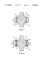
- FIG. 7 is a cross-sectional view which illustrates another alternative means for securing such bearing assembly to such male connection member.
- FIG. 8 is a cross-sectional view which illustrates another alternative means for securing such bearing assembly to such male connection member.
- the present invention can be used in conjunction with the articulated type coupling arrangements taught in our co-pending and earlier filed U.S. patent application having serial numbers 07/520686 (U.S. Pat. No. 5,131,331) and 07/520,687 (U.S. Pat. No. 5,065,679), filed on May 8, 1990.
- serial numbers 07/520686 U.S. Pat. No. 5,131,331
- 07/520,687 U.S. Pat. No. 5,065,679
- FIGS. 1 and 2 in which the male connection member, generally designated 10, constructed according to a presently preferred embodiment of the invention, is illustrated.
- This male connection member 10 is useful in an articulated type coupling arrangement (not shown) and can be rather easily retrofitted to existing railway cars as well as being easily installed on new cars when they are built.
- An articulated type coupling arrangement as taught in our co-pending application referenced above is capable of connecting together, in a substantially semi-permanent manner, at least one predetermined end (not shown) of a first railway car (not shown) and an adjacent predetermined end (not shown) of a second railway car (not shown).
- the male connection member 10 includes a first end portion 12 having a predetermined configuration.
- Such predetermined configuration of such first end portion 12 enables the male connection member 10 to be engaged with and connected to a predetermined end (not shown) of a center sill member (not shown).
- a center sill member is disposed substantially along a longitudinal centerline of a railway car to be connected in such semipermanent fashion.
- the male connection member 10 includes a second end portion 14 having a predetermined size and a predetermined shape.
- Such second end portion 14 is preferably formed integrally with the first end portion 12 and it is disposed substantially axially opposite such first end portion 12.
- the second end portion 14 includes an outer end surface 16 which has a predetermined configuration. This predetermined configuration of the outer end surface 16 is such that it will ensure that no contact between the outer end surface 16 of such second end portion 14 and other components (not shown) of such articulated type coupling arrangement will occur.
- An aperture 18 is formed through a predetermined portion of such second end portion 14 of this male connection member 10.
- Such aperture 18 has a predetermined size and a predetermined shape.
- a longitudinal axis of such aperture 18 is disposed transverse to a longitudinal axis of such male connection member 10. Further, such longitudinal axis of such aperture 18 is positioned in a substantially horizontal plane.
- the male connection member 10 includes a means, generally designated 30, formed in such second end portion 14 adjacent an outer edge 24 of the aperture 18 which enables a bearing assembly, generally designated 40, to be secured in place to the second end portion 14 of the male connection member 10.
- the first end portion 12 and the second end portion 14 of the male connection member 10 will be formed integrally as a simple piece casting.
- such aperture 18 will be cast into the second end portion 14 at the same time. In most instances it will be preferred for such aperture 18 to be cast as a substantially round opening even though other shapes would be within the scope of the invention.
- the outer end surface 16 of the second end portion 14 prefferably has a substantially convex configuration in at least one of a horizontal direction and a vertical direction. It is even more preferred for this outer end surface 16 to be substantially convex in both such horizontal direction and such vertical direction.
- the predetermined configuration of the second end portion 14 preferably includes a tapered portion of a bottom wall surface 26 which extends upwardly from the outermost end 16 thereof and inwardly towards the first end portion 12. If desired, this predetermined configuration may also include a tapered portion of the top wall surface 28 which extends downwardly from such outermost end 16 of the second end portion 14 towards the first end portion 12 of the male connection member 10. This may be desirable, for example, to reduce the total weight of such male connection member 10. As part of the preferred configuration of the second end portion 14, the side wall portions 32 will be substantially parallel to one another.
- the first end portion 12 will have a configuration, at least in the area where it will be engaged with and connected to the center sill member, that is substantially rectangular in cross-section.
- the bearing assembly 40 includes a substantially spherical member 34. At least a portion of the spherical member 34 is disposed within a race assembly 36.
- the outer surface 38 of such race assembly 36 is substantially identical in size and shape as an inner surface 42 of the aperture 18. If, for some reason, it is desirable to secure the bearing assembly 40 into the aperture 18 in a substantially permanent manner, such as by welding, the means 30 provided to accomplish this will include at least one beveled portion 44 adjacent at least one predetermined outer surface of the aperture 18.
- an adjacent outer edge surface of the race assembly 36 will also include a beveled portion 46 so that weld metal 48 can be applied to hold the race assembly 36 within the aperture 18 of such male connection member 10.
- the beveled portion 44 is tapered downwardly from an outer side surface of the second end portion 14 of such male connection member 10 and inwardly toward the peripheral surface of the aperture 18 formed therein.
- the beveled portion 46 disposed on the outer edge of the race assembly 36 is tapered downwardly from an outer side surface thereof, which is in substantially the same plane as the outer side surface of the second end portion 14, and inwardly toward such peripheral surface of such aperture 18.
- FIG. 3 illustrates another beveled portion 50, disposed on the second end 14 of the male connection member 10, which is abuttingly engaged with another beveled portion 52 disposed on the race assembly 36.
- Such beveled portion 50 is tapered inwardly from the outer side surface of the second end portion 14 and downwardly toward such aperture 18 disposed therein.
- FIG. 4 illustrates welding of such axially opposed side of the race assembly 36 to the second end portion 14 of the male connection member 10 adjacent the aperture 18.
- the second end portion 14 includes a beveled portion 54 which is tapered downwardly from another outer side surface of the second end portion 14 and inwardly toward such peripheral surface of such aperture 18.
- the race assembly in this case, includes a beveled portion 56, which is tapered downwardly from an outer side surface of such race assembly 36, which is in substantially the same plane as such another outer side surface of the second end portion 14, and inwardly toward such peripheral surface of the aperture 18 so that weld metal 58 can be applied to hold the race assembly 36 securely in place within the aperture 18.
- the axially opposed sides of the race assembly 36 can be held in place by a ledge member 60 disposed on one of the second end portion 14 adjacent such aperture 18 engaged with a complimentary recessed portion 62 disposed on the race assembly 36.
- the ledge member could be part of the race assembly 36 and the recessed portion 62 could be on the second end portion 14 of the male connection member 10.
- FIGS. 5, 6 and 8 illustrate arrangements for removably securing such race assembly 36 to such aperture 18 in the second end portion 14 of the male connection member 10.
- a ledge portion 60 disposed on the second end portion 14, extends into the aperture 18.
- Such ledge portion 60 abuttingly engages a recess 62 formed on an outer surface of the race assembly 36 for securing one side of the race assembly 36 within the aperture 18.
- the opposed other side of the race assembly 36 is secured in the aperture 18 by means of a plate-like member or flange 64 secured to the second end portion 14 of the male connection member 10 by bolts 66.
- the plate-like member 64 includes a first portion disposed in a recess or flange seat 68 formed on the second end portion 14 and a second end portion of the plate-like member 64 is disposed in a recess formed on the race assembly 36.
- a ledge could be formed on the race assembly which could be bolted to such a second end portion 14 of the male connection member 10.
- FIG. 6 illustrates using a combination including features illustrated in FIGS. 3 and 8.
- FIG. 8 illustrates the use of two-plate like members 64.
Landscapes
- Engineering & Computer Science (AREA)
- Mechanical Engineering (AREA)
- Connection Of Plates (AREA)
Abstract
Description
Claims (19)
Priority Applications (1)
| Application Number | Priority Date | Filing Date | Title |
|---|---|---|---|
| US07/586,524 US5219082A (en) | 1990-09-21 | 1990-09-21 | Male connection member for an articulated coupling arrangement |
Applications Claiming Priority (1)
| Application Number | Priority Date | Filing Date | Title |
|---|---|---|---|
| US07/586,524 US5219082A (en) | 1990-09-21 | 1990-09-21 | Male connection member for an articulated coupling arrangement |
Publications (1)
| Publication Number | Publication Date |
|---|---|
| US5219082A true US5219082A (en) | 1993-06-15 |
Family
ID=24346096
Family Applications (1)
| Application Number | Title | Priority Date | Filing Date |
|---|---|---|---|
| US07/586,524 Expired - Lifetime US5219082A (en) | 1990-09-21 | 1990-09-21 | Male connection member for an articulated coupling arrangement |
Country Status (1)
| Country | Link |
|---|---|
| US (1) | US5219082A (en) |
Cited By (13)
| Publication number | Priority date | Publication date | Assignee | Title |
|---|---|---|---|---|
| US6176379B1 (en) * | 1999-01-29 | 2001-01-23 | Westinghouse Air Brake Company | Ball and race assembly including a one piece race member integrally formed with the ball |
| US20020108921A1 (en) * | 1998-09-16 | 2002-08-15 | Ring Michael E. | Slackless drawbar assembly using an improved ball and race connection assembly |
| US6564956B2 (en) * | 1998-11-20 | 2003-05-20 | Westinghouse Air Brake Technologies Corporation | Retainer member for use in railway coupling devices |
| US6688482B1 (en) * | 1998-11-20 | 2004-02-10 | Westinghouse Air Brake Technologies Corporation | Connection assembly for railway coupling devices |
| US6691883B1 (en) * | 1998-11-20 | 2004-02-17 | Westinghouse Air Brake Co. | One piece liner member for use in railway coupling devices |
| US20060237383A1 (en) * | 2005-03-22 | 2006-10-26 | Modoplex S.R.L. | Display with variable configuration |
| WO2007044811A1 (en) * | 2005-10-13 | 2007-04-19 | Wabtec Holding Corporation | Locking arrangement for a bearing assembly of a male connection member for an articulated coupling apparatus |
| WO2007104643A1 (en) * | 2006-03-11 | 2007-09-20 | Schaeffler Kg | Jointed coupling for rail vehicles |
| US20110031265A1 (en) * | 2008-04-10 | 2011-02-10 | Sca Hygiene Products Ab | Paper towel dispenser |
| CN105292166A (en) * | 2015-11-30 | 2016-02-03 | 南车株洲电力机车有限公司 | Hinge assembly for connection of rolling stock |
| CN109927746A (en) * | 2017-12-15 | 2019-06-25 | 株洲春华实业有限责任公司 | A kind of hitch |
| CN109927750A (en) * | 2017-12-15 | 2019-06-25 | 株洲春华实业有限责任公司 | A kind of hitch |
| CN109927744A (en) * | 2017-12-15 | 2019-06-25 | 株洲春华实业有限责任公司 | A kind of hitch |
Citations (11)
| Publication number | Priority date | Publication date | Assignee | Title |
|---|---|---|---|---|
| US1067892A (en) * | 1912-12-14 | 1913-07-22 | Mechanical Devices Co Inc | Shaft-hanger. |
| US2013546A (en) * | 1932-11-19 | 1935-09-03 | Wallace Allen | Articulated joint |
| DE703249C (en) * | 1939-08-17 | 1941-03-05 | Kloeckner Humboldt Deutz Akt G | Storage of the upper end of double cone crushers |
| US3068551A (en) * | 1958-08-29 | 1962-12-18 | Gen Motors Corp | Method of assembling a self-aligning bearing |
| CA657948A (en) * | 1963-02-19 | S. Benevall Erik | Self-lubricating bearing | |
| US3700295A (en) * | 1971-12-03 | 1972-10-24 | Rex Chainbelt Inc | Ball and socket bearing |
| US4095856A (en) * | 1977-01-24 | 1978-06-20 | Brighton Corporation | Adjustable bottom step bearing |
| US4258628A (en) * | 1979-06-11 | 1981-03-31 | Amsted Industries Incorporated | Articulated railway coupling |
| US4336758A (en) * | 1980-06-13 | 1982-06-29 | Amsted Industries Incorporated | Railroad car sill-articulating device member connection |
| US4593829A (en) * | 1983-12-15 | 1986-06-10 | Amsted Industries Incorporated | Articulated railway car connection with guided slack adjusting wedges |
| US4867071A (en) * | 1988-04-13 | 1989-09-19 | National Castings, Inc. | Truck-mounted articulated connector for railway cars |
-
1990
- 1990-09-21 US US07/586,524 patent/US5219082A/en not_active Expired - Lifetime
Patent Citations (11)
| Publication number | Priority date | Publication date | Assignee | Title |
|---|---|---|---|---|
| CA657948A (en) * | 1963-02-19 | S. Benevall Erik | Self-lubricating bearing | |
| US1067892A (en) * | 1912-12-14 | 1913-07-22 | Mechanical Devices Co Inc | Shaft-hanger. |
| US2013546A (en) * | 1932-11-19 | 1935-09-03 | Wallace Allen | Articulated joint |
| DE703249C (en) * | 1939-08-17 | 1941-03-05 | Kloeckner Humboldt Deutz Akt G | Storage of the upper end of double cone crushers |
| US3068551A (en) * | 1958-08-29 | 1962-12-18 | Gen Motors Corp | Method of assembling a self-aligning bearing |
| US3700295A (en) * | 1971-12-03 | 1972-10-24 | Rex Chainbelt Inc | Ball and socket bearing |
| US4095856A (en) * | 1977-01-24 | 1978-06-20 | Brighton Corporation | Adjustable bottom step bearing |
| US4258628A (en) * | 1979-06-11 | 1981-03-31 | Amsted Industries Incorporated | Articulated railway coupling |
| US4336758A (en) * | 1980-06-13 | 1982-06-29 | Amsted Industries Incorporated | Railroad car sill-articulating device member connection |
| US4593829A (en) * | 1983-12-15 | 1986-06-10 | Amsted Industries Incorporated | Articulated railway car connection with guided slack adjusting wedges |
| US4867071A (en) * | 1988-04-13 | 1989-09-19 | National Castings, Inc. | Truck-mounted articulated connector for railway cars |
Non-Patent Citations (1)
| Title |
|---|
| Maintenance Manual for ASF Articulated Connection Assembly. * |
Cited By (29)
| Publication number | Priority date | Publication date | Assignee | Title |
|---|---|---|---|---|
| US20020108921A1 (en) * | 1998-09-16 | 2002-08-15 | Ring Michael E. | Slackless drawbar assembly using an improved ball and race connection assembly |
| US6938786B2 (en) * | 1998-09-16 | 2005-09-06 | Westinghouse Air Brake Technologies Corporation | Slackless drawbar assembly using an improved ball and race connection assembly |
| US6564956B2 (en) * | 1998-11-20 | 2003-05-20 | Westinghouse Air Brake Technologies Corporation | Retainer member for use in railway coupling devices |
| US6688482B1 (en) * | 1998-11-20 | 2004-02-10 | Westinghouse Air Brake Technologies Corporation | Connection assembly for railway coupling devices |
| US6691883B1 (en) * | 1998-11-20 | 2004-02-17 | Westinghouse Air Brake Co. | One piece liner member for use in railway coupling devices |
| US6176379B1 (en) * | 1999-01-29 | 2001-01-23 | Westinghouse Air Brake Company | Ball and race assembly including a one piece race member integrally formed with the ball |
| US20060237383A1 (en) * | 2005-03-22 | 2006-10-26 | Modoplex S.R.L. | Display with variable configuration |
| RU2421357C2 (en) * | 2005-10-13 | 2011-06-20 | Уобтек Холдинг Корпорейшн | Male joint part bearing assembly lock for articulated coupling |
| CN101973283B (en) * | 2005-10-13 | 2014-07-09 | 西屋气动刹车技术公司 | Locking arrangement for a bearing assembly of a male connection member for an articulated coupling apparatus |
| US7467724B2 (en) * | 2005-10-13 | 2008-12-23 | Wabtec Holding Corp. | Locking arrangement for a bearing assembly of a male connection member for an articulated coupling apparatus |
| US20070084817A1 (en) * | 2005-10-13 | 2007-04-19 | Wabtec Holding Corp. | Locking arrangement for a bearing assembly of a male connection member for an articulated coupling apparatus |
| WO2007044811A1 (en) * | 2005-10-13 | 2007-04-19 | Wabtec Holding Corporation | Locking arrangement for a bearing assembly of a male connection member for an articulated coupling apparatus |
| AU2006302076B2 (en) * | 2005-10-13 | 2011-08-25 | Wabtec Holding Corporation | Locking arrangement for a bearing assembly of a male connection member for an articulated coupling apparatus |
| CN101287635B (en) * | 2005-10-13 | 2011-11-02 | 西屋气动刹车技术公司 | Locking device for bearing assemblies of bushing couplings for movable coupler units |
| KR101219982B1 (en) | 2005-10-13 | 2013-01-09 | 왑텍 홀딩 코포레이션 | A male connection member and locking arrangement |
| WO2007104643A1 (en) * | 2006-03-11 | 2007-09-20 | Schaeffler Kg | Jointed coupling for rail vehicles |
| US20090101615A1 (en) * | 2006-03-11 | 2009-04-23 | Andreas Krome | Articulated Joint Coupling |
| US7832575B2 (en) * | 2006-03-11 | 2010-11-16 | Schaeffler Kg | Articulated joint coupling |
| RU2424930C2 (en) * | 2006-03-11 | 2011-07-27 | Шеффлер Кг | Hinged coupling for railway transport facilities |
| CN101400560B (en) * | 2006-03-11 | 2012-03-21 | 谢夫勒科技有限两合公司 | Jointed coupling for rail vehicles |
| US20110031265A1 (en) * | 2008-04-10 | 2011-02-10 | Sca Hygiene Products Ab | Paper towel dispenser |
| US8616408B2 (en) * | 2008-04-10 | 2013-12-31 | Sca Hygiene Products Ab | Paper towel dispenser |
| CN105292166A (en) * | 2015-11-30 | 2016-02-03 | 南车株洲电力机车有限公司 | Hinge assembly for connection of rolling stock |
| CN105292166B (en) * | 2015-11-30 | 2018-05-08 | 南车株洲电力机车有限公司 | A kind of articulated mounting of rolling stock connection |
| CN109927746A (en) * | 2017-12-15 | 2019-06-25 | 株洲春华实业有限责任公司 | A kind of hitch |
| CN109927750A (en) * | 2017-12-15 | 2019-06-25 | 株洲春华实业有限责任公司 | A kind of hitch |
| CN109927744A (en) * | 2017-12-15 | 2019-06-25 | 株洲春华实业有限责任公司 | A kind of hitch |
| CN109927750B (en) * | 2017-12-15 | 2024-12-10 | 株洲春华实业有限责任公司 | A car coupler |
| CN109927746B (en) * | 2017-12-15 | 2024-12-10 | 株洲春华实业有限责任公司 | A car coupler |
Similar Documents
| Publication | Publication Date | Title |
|---|---|---|
| US5271511A (en) | Removable shaft member engageable in a ball portion of articulated bearing assembly | |
| US4580686A (en) | Slackless self-adjusting rotary drawbar for railroad cars | |
| US5219082A (en) | Male connection member for an articulated coupling arrangement | |
| EP0456221B1 (en) | Articulated coupling apparatus for connecting a pair of railway cars together | |
| US5172819A (en) | Bearing assembly for an articulated coupling apparatus which connects adjacent ends of a pair of railway cars together | |
| US5360124A (en) | Slackless buff gear connection system with sliding yoke casting | |
| US5598937A (en) | Slackless drawbar assembly | |
| US4966291A (en) | Slackless rotary drawbar assembly | |
| US5042393A (en) | Locking assembly to secure a bearing assembly in an articulated coupling apparatus for connecting adjacent ends of a pair of railway cars | |
| EP0456222B1 (en) | Bearing assembly for an articulated coupling apparatus | |
| US5105955A (en) | Spherical connector apparatus in an articulated slackless-type coupler arrangement used in a railway application | |
| US5131331A (en) | Articulated coupling apparatus for connecting adjacent ends of a pair of railway cars | |
| US5277323A (en) | Locking wedge assembly to removably secure a male connection member in an articulated-type coupling arrangement | |
| US6167813B1 (en) | Tapered wear liner and articulated connector with tapered wear liner | |
| US5427257A (en) | Drawbar assembly yoke casting | |
| US5167334A (en) | Apparatus to provide versatility in securing male and female connection members of an articulated coupler to a center sill member of a railway car | |
| US5415304A (en) | Yoke casting for a drawbar assembly | |
| EP0751055B1 (en) | Freight railway car slackless drawbar assembly | |
| US5054630A (en) | Slackless coupler connection for a railway vehicle | |
| US5115927A (en) | Strengthening mechanism for a female articulated coupling member for providing additional strength in response to loads exerted at bearing assembly connection shaft | |
| US5080243A (en) | Assembly mechanism for an articulated coupling system | |
| US5172820A (en) | Female connection member used in an articulated coupling arrangement | |
| US5139159A (en) | Connecting pin for articulated coupling arrangement | |
| US5167333A (en) | Apparatus to prevent detrimental extraneous foreign matter from entering a cavity formed at an outer end of a female connection member of an articulated coupling | |
| US5092204A (en) | Apparatus for aligning spherical member during assembly of an articulated coupling system |
Legal Events
| Date | Code | Title | Description |
|---|---|---|---|
| AS | Assignment |
Owner name: WESTINGHOUSE AIR BRAKE COMPANY A CORP. OF DELAWA Free format text: ASSIGNMENT OF 1/2 OF ASSIGNORS INTEREST;ASSIGNORS:HAWRYSZKOW, MICHAEL G.;WALLACE, WILLIAM D.;LYNCH, EDWARD G. JR.;AND OTHERS;REEL/FRAME:005693/0756;SIGNING DATES FROM 19910425 TO 19910501 Owner name: SARGENT INDUSTRIES, INC. A CORP. OF DELAWARE, WI Free format text: ASSIGNMENT OF 1/2 OF ASSIGNORS INTEREST;ASSIGNORS:HAWRYSZKOW, MICHAEL G.;WALLACE, WILLIAM D.;LYNCH, EDWARD G. JR.;AND OTHERS;REEL/FRAME:005693/0756;SIGNING DATES FROM 19910425 TO 19910501 |
|
| STCF | Information on status: patent grant |
Free format text: PATENTED CASE |
|
| AS | Assignment |
Owner name: DELAWARE CAPITAL HOLDINGS, INC., DELAWARE Free format text: ASSIGNMENT OF ASSIGNORS INTEREST;ASSIGNOR:SARGENT INDUSTRIES, INC.;REEL/FRAME:006847/0097 Effective date: 19930901 Owner name: DELAWARE CAPITAL FORMATION, INC., DELAWARE Free format text: ASSIGNMENT OF ASSIGNORS INTEREST;ASSIGNOR:DELAWARE CAPITAL HOLDINGS, INC.;REEL/FRAME:006839/0862 Effective date: 19930901 |
|
| CC | Certificate of correction | ||
| FPAY | Fee payment |
Year of fee payment: 4 |
|
| AS | Assignment |
Owner name: CHASE MANHATTAN BANK, THE, NEW YORK Free format text: SECURITY INTEREST;ASSIGNOR:WESTINGHOUSE AIR BRAKE COMPANY;REEL/FRAME:009423/0239 Effective date: 19980630 |
|
| FEPP | Fee payment procedure |
Free format text: PAYOR NUMBER ASSIGNED (ORIGINAL EVENT CODE: ASPN); ENTITY STATUS OF PATENT OWNER: LARGE ENTITY |
|
| FPAY | Fee payment |
Year of fee payment: 8 |
|
| AS | Assignment |
Owner name: WESTINGHOUSE AIR BRAKE COMPANY, PENNSYLVANIA Free format text: TERMINATION OF SECURITY INTEREST RECORDAL STARTING AT REEL/FRAME 9423/0239.;ASSIGNOR:CHASE MANHATTAN BANK, AS COLLATERAL AGENT, THE;REEL/FRAME:012280/0283 Effective date: 20010501 |
|
| FPAY | Fee payment |
Year of fee payment: 12 |