US5211543A - Liquid-ring pump with pressure chamber valve plate - Google Patents
Liquid-ring pump with pressure chamber valve plate Download PDFInfo
- Publication number
- US5211543A US5211543A US07/865,997 US86599792A US5211543A US 5211543 A US5211543 A US 5211543A US 86599792 A US86599792 A US 86599792A US 5211543 A US5211543 A US 5211543A
- Authority
- US
- United States
- Prior art keywords
- liquid
- ring pump
- bushings
- pins
- pump according
- Prior art date
- Legal status (The legal status is an assumption and is not a legal conclusion. Google has not performed a legal analysis and makes no representation as to the accuracy of the status listed.)
- Expired - Lifetime
Links
- 238000007789 sealing Methods 0.000 claims description 8
- 238000007689 inspection Methods 0.000 claims description 3
- 230000000149 penetrating effect Effects 0.000 abstract description 2
- NMFHJNAPXOMSRX-PUPDPRJKSA-N [(1r)-3-(3,4-dimethoxyphenyl)-1-[3-(2-morpholin-4-ylethoxy)phenyl]propyl] (2s)-1-[(2s)-2-(3,4,5-trimethoxyphenyl)butanoyl]piperidine-2-carboxylate Chemical compound C([C@@H](OC(=O)[C@@H]1CCCCN1C(=O)[C@@H](CC)C=1C=C(OC)C(OC)=C(OC)C=1)C=1C=C(OCCN2CCOCC2)C=CC=1)CC1=CC=C(OC)C(OC)=C1 NMFHJNAPXOMSRX-PUPDPRJKSA-N 0.000 description 7
- 238000010276 construction Methods 0.000 description 1
- 230000002950 deficient Effects 0.000 description 1
- 238000006073 displacement reaction Methods 0.000 description 1
Images


Classifications
-
- F—MECHANICAL ENGINEERING; LIGHTING; HEATING; WEAPONS; BLASTING
- F04—POSITIVE - DISPLACEMENT MACHINES FOR LIQUIDS; PUMPS FOR LIQUIDS OR ELASTIC FLUIDS
- F04C—ROTARY-PISTON, OR OSCILLATING-PISTON, POSITIVE-DISPLACEMENT MACHINES FOR LIQUIDS; ROTARY-PISTON, OR OSCILLATING-PISTON, POSITIVE-DISPLACEMENT PUMPS
- F04C29/00—Component parts, details or accessories of pumps or pumping installations, not provided for in groups F04C18/00 - F04C28/00
- F04C29/12—Arrangements for admission or discharge of the working fluid, e.g. constructional features of the inlet or outlet
- F04C29/124—Arrangements for admission or discharge of the working fluid, e.g. constructional features of the inlet or outlet with inlet and outlet valves specially adapted for rotary or oscillating piston pumps
- F04C29/126—Arrangements for admission or discharge of the working fluid, e.g. constructional features of the inlet or outlet with inlet and outlet valves specially adapted for rotary or oscillating piston pumps of the non-return type
- F04C29/128—Arrangements for admission or discharge of the working fluid, e.g. constructional features of the inlet or outlet with inlet and outlet valves specially adapted for rotary or oscillating piston pumps of the non-return type of the elastic type, e.g. reed valves
-
- F—MECHANICAL ENGINEERING; LIGHTING; HEATING; WEAPONS; BLASTING
- F04—POSITIVE - DISPLACEMENT MACHINES FOR LIQUIDS; PUMPS FOR LIQUIDS OR ELASTIC FLUIDS
- F04C—ROTARY-PISTON, OR OSCILLATING-PISTON, POSITIVE-DISPLACEMENT MACHINES FOR LIQUIDS; ROTARY-PISTON, OR OSCILLATING-PISTON, POSITIVE-DISPLACEMENT PUMPS
- F04C19/00—Rotary-piston pumps with fluid ring or the like, specially adapted for elastic fluids
- F04C19/005—Details concerning the admission or discharge
- F04C19/007—Port members in the form of side plates
Definitions
- the present invention relates to a liquid-ring pump and more specifically to a liquid-ring pump having an impeller rotatably accommodated in its pump chamber.
- the pump chamber is formed by the pump's housing and is closed off by a disk cam showing an inlet slit and several output ports.
- the disk cam is covered by a slide shield configured on the pump housing.
- a suction chamber connected to the inlet slit and a pressure chamber connected to the output ports.
- German Printed Patent 27 04 863 discloses a liquid-ring pump.
- valve plates and collector plates are arranged and secured on the disk cam. This construction increases assembly expenditure. Furthermore, if the valve plate is destroyed or worn out during later pump operation, the side shield must be disassembled when replacing the valve plate.
- the present invention discloses a generic type of liquid-ring pump in which installing the valve plate in front of the output ports is considerably easier than in conventional liquid-ring pumps.
- the present invention achieves this improved arrangement by having the collector plate connected to the side shield, and having the valve plate guided by guide elements penetrating through openings in the valve plate which are arranged between the collector plate and the disk cam. Specially assembling the collector plate on the disk cam is no longer necessary because the collector plate is connected to the side shield. The valve plate only needs to be slipped on to the guide elements. Since the valve plate is no longer clamped on one side, it can lift up from all the output ports by the same distance, so that the gas is not hindered from escaping out of the output ports.
- Another way to facilitate the pump assembly of the present invention is to premold the collector plate in one piece on the side shield.
- the collector plate is provided on a sealing plate so that exchanging a defective valve plate or controlling its operativeness without disassembling larger pump parts is possible.
- This sealing plate is used to cover an inspection opening provided in the side shield.
- the valve plate can be mounted on the guide elements before the side shield or the sealing plate is assembled since pins or bushings are provided as guide elements. These guide elements mate with corresponding location holes on the collector plate and/or on the disk cam. Another way to facilitate the assembly of the present invention is to secure the pins or bushings in the location holes of the collector plate or of the disk cam.
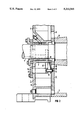
- FIG. 1 is a partial-sectional view of a liquid-ring pump, in which a collector plate is premolded on the side shield according to an embodiment of the present invention.
- FIG. 2 is a partial-sectional view of a liquid-ring pump, in which the collector plate is configured on a sealing plate, capable of being attached to the side shield according to another embodiment of the present invention.
- FIG. 3 is a top view of a side shield with a premolded collector plate.
- Element 1 denotes a side shield which is installed on the pump housing 2 of a liquid-ring pump.
- This side shield 1 has a shaft bore hole 3, through which the shaft 4 of the pump's impeller 5 is sealingly accommodated.
- a disk cam 6, which occludes the pump chamber at the front end, is arranged between the side shield 1 and the pump housing 2.
- This disk cam 6 has at least one inlet slit 8, providing an opening to the suction chamber 7 of the side shield 1.
- the disk cam 6 also has several output ports 10, which provide an opening to the pressure chamber 9 of the side shield 1. Only one of the output ports 10 is depicted in the drawings. The area of the disk cam 6 provided with the output ports 10 is shown rotated in the drawing plane.
- valve plate 11 Assigned to each of the output ports 10 is a valve plate 11, which either clears or covers the output ports 10 based on prevailing operating conditions.
- a collector plate 12, premolded on the side shield 1, is allocated to the valve plate 11.
- Pins or bushings 14 are inserted with their ends in mutually opposing location holes 13 provided on the collector plate 12 and on the disk cam 6.
- the pins or bushings 14 penetrate through guide openings 15 existing on the valve plate 11.
- the valve plate 11 is secured in terms of position opposite the output ports 10.
- Axially shifting the valve plate 11 about the pins or bushings 14 in the area between the disk cam 6 and the collector plate 12 is possible.
- the axial shifting of the valve plate 11 causes the output ports 10 to open or close based on the displacement direction.
- Individual output ports 10 or all of the output ports 10 are closed or opened based on prevailing pressure conditions.
- FIG. 2 depicts another embodiment of the present invention of a liquid-ring pump, where the collector plate 12 is provided on a sealing plate 16, which serves to close an inspection opening 17 in the side shield 1. After this sealing plate 16 is removed, the valve plate 11 can be controlled or even replaced when damaged.
- the pins or bushings 14 can either be secured in the location holes 13 of the disk cam 6 or in the location holes 13 of the collector plate 12.
- the valve plate 11 with its guide openings 15 is mounted on these secured pins or bushings 14.
- the pins or bushings 14 then mate with the opposite location holes 13 of the collector plate 12 or of the disk cam 6. Thus, the valve plate 11 is completely secured.
Landscapes
- Engineering & Computer Science (AREA)
- Mechanical Engineering (AREA)
- General Engineering & Computer Science (AREA)
- Structures Of Non-Positive Displacement Pumps (AREA)
Abstract
Description
Claims (24)
Applications Claiming Priority (2)
| Application Number | Priority Date | Filing Date | Title |
|---|---|---|---|
| DE9106151[U] | 1991-05-17 | ||
| DE9106151U DE9106151U1 (en) | 1991-05-17 | 1991-05-17 | Liquid ring pump |
Publications (1)
| Publication Number | Publication Date |
|---|---|
| US5211543A true US5211543A (en) | 1993-05-18 |
Family
ID=6867444
Family Applications (1)
| Application Number | Title | Priority Date | Filing Date |
|---|---|---|---|
| US07/865,997 Expired - Lifetime US5211543A (en) | 1991-05-17 | 1992-04-09 | Liquid-ring pump with pressure chamber valve plate |
Country Status (6)
| Country | Link |
|---|---|
| US (1) | US5211543A (en) |
| EP (1) | EP0519192B1 (en) |
| JP (1) | JPH05157075A (en) |
| AU (1) | AU646562B2 (en) |
| CA (1) | CA2068812A1 (en) |
| DE (2) | DE9106151U1 (en) |
Cited By (2)
| Publication number | Priority date | Publication date | Assignee | Title |
|---|---|---|---|---|
| DE29805345U1 (en) | 1998-03-24 | 1998-08-06 | Siemens AG, 80333 München | Liquid ring pump |
| US6287082B1 (en) * | 1997-06-30 | 2001-09-11 | Siemens Aktiengesellschaft | Liquid ring pump |
Families Citing this family (1)
| Publication number | Priority date | Publication date | Assignee | Title |
|---|---|---|---|---|
| WO2013076176A1 (en) * | 2011-11-24 | 2013-05-30 | Sterling Industry Consult Gmbh | Liquid-ring vacuum pump |
Citations (2)
| Publication number | Priority date | Publication date | Assignee | Title |
|---|---|---|---|---|
| US3366314A (en) * | 1965-04-28 | 1968-01-30 | Siemens Ag | Rotary vacuum pump of the liquid-ring type |
| GB2064002A (en) * | 1979-11-22 | 1981-06-10 | Graham Precision Pumps Ltd | Liquid Ring Vacuum Pumps |
Family Cites Families (3)
| Publication number | Priority date | Publication date | Assignee | Title |
|---|---|---|---|---|
| US1931198A (en) * | 1930-11-26 | 1933-10-17 | Norge Corp | Compressor discharge valve |
| DE3337837A1 (en) * | 1983-10-18 | 1985-04-25 | Siemens AG, 1000 Berlin und 8000 München | LIQUID RING PUMP |
| GB2217814B (en) * | 1988-04-27 | 1992-10-14 | American Standard Inc | Rotary compressors having backflow preventing valves |
-
1991
- 1991-05-17 DE DE9106151U patent/DE9106151U1/en not_active Expired - Lifetime
-
1992
- 1992-04-09 US US07/865,997 patent/US5211543A/en not_active Expired - Lifetime
- 1992-04-30 EP EP92107460A patent/EP0519192B1/en not_active Expired - Lifetime
- 1992-04-30 DE DE59201384T patent/DE59201384D1/en not_active Expired - Fee Related
- 1992-05-13 JP JP4146948A patent/JPH05157075A/en not_active Withdrawn
- 1992-05-15 AU AU16339/92A patent/AU646562B2/en not_active Ceased
- 1992-05-15 CA CA002068812A patent/CA2068812A1/en not_active Abandoned
Patent Citations (2)
| Publication number | Priority date | Publication date | Assignee | Title |
|---|---|---|---|---|
| US3366314A (en) * | 1965-04-28 | 1968-01-30 | Siemens Ag | Rotary vacuum pump of the liquid-ring type |
| GB2064002A (en) * | 1979-11-22 | 1981-06-10 | Graham Precision Pumps Ltd | Liquid Ring Vacuum Pumps |
Cited By (2)
| Publication number | Priority date | Publication date | Assignee | Title |
|---|---|---|---|---|
| US6287082B1 (en) * | 1997-06-30 | 2001-09-11 | Siemens Aktiengesellschaft | Liquid ring pump |
| DE29805345U1 (en) | 1998-03-24 | 1998-08-06 | Siemens AG, 80333 München | Liquid ring pump |
Also Published As
| Publication number | Publication date |
|---|---|
| JPH05157075A (en) | 1993-06-22 |
| EP0519192B1 (en) | 1995-02-15 |
| EP0519192A1 (en) | 1992-12-23 |
| AU646562B2 (en) | 1994-02-24 |
| DE59201384D1 (en) | 1995-03-23 |
| CA2068812A1 (en) | 1992-11-18 |
| DE9106151U1 (en) | 1992-09-17 |
| AU1633992A (en) | 1992-11-19 |
Similar Documents
| Publication | Publication Date | Title |
|---|---|---|
| EP0557023A1 (en) | Scroll type compressor with variable displacement mechanism | |
| EP0844012B1 (en) | Oil filter | |
| US6123516A (en) | Vacuum pump | |
| MY119499A (en) | Scroll compressor having bypass valves | |
| CN118661064A (en) | Variable Capacity Bypass Valves for Screw Compressors | |
| KR970046741A (en) | Safety relief valve assembly | |
| US5211543A (en) | Liquid-ring pump with pressure chamber valve plate | |
| CN110637160B (en) | Insertion type vane pump and pump device comprising same | |
| CN111472977B (en) | Valve assembly and compressor | |
| KR100302412B1 (en) | Pilot Switching Valve | |
| US11649907B2 (en) | Valve, modular system for manufacturing valves, and method of manufacturing valves | |
| CA2017371A1 (en) | Flapper check valve | |
| KR19990013278A (en) | Fuel pump | |
| KR970075376A (en) | Rotor type pump | |
| JP3959562B2 (en) | Pilot type switching valve | |
| EP0179311B1 (en) | Liquid-ring compressor | |
| JPH05172075A (en) | compressor | |
| CN117365954A (en) | Non-orbiting scroll assembly, scroll compressor and method of machining non-orbiting scroll assembly | |
| JP2001173831A (en) | Solenoid valve manifold | |
| EP3822523A1 (en) | Spool valve | |
| EP1640570A1 (en) | Electromagnetic valve unit and engine cover unit | |
| JP2003097455A (en) | Vane pump | |
| KR930003890Y1 (en) | Vane pump sealing | |
| EP3842639B1 (en) | Circulation pump for a fluid | |
| GB2102888A (en) | Rotary positive-displacement pumps |
Legal Events
| Date | Code | Title | Description |
|---|---|---|---|
| AS | Assignment |
Owner name: SIEMENS AKTIENGESELLSCHAFT, GERMANY Free format text: ASSIGNMENT OF ASSIGNORS INTEREST.;ASSIGNORS:SIEBENWURST, ROBERT;TRIMBORN, PETER;REEL/FRAME:006086/0569 Effective date: 19920323 |
|
| STCF | Information on status: patent grant |
Free format text: PATENTED CASE |
|
| FEPP | Fee payment procedure |
Free format text: PAYOR NUMBER ASSIGNED (ORIGINAL EVENT CODE: ASPN); ENTITY STATUS OF PATENT OWNER: LARGE ENTITY |
|
| FPAY | Fee payment |
Year of fee payment: 4 |
|
| FPAY | Fee payment |
Year of fee payment: 8 |
|
| FEPP | Fee payment procedure |
Free format text: PAYOR NUMBER ASSIGNED (ORIGINAL EVENT CODE: ASPN); ENTITY STATUS OF PATENT OWNER: LARGE ENTITY Free format text: PAYER NUMBER DE-ASSIGNED (ORIGINAL EVENT CODE: RMPN); ENTITY STATUS OF PATENT OWNER: LARGE ENTITY |
|
| AS | Assignment |
Owner name: NASH-ELMO INDUSTRIES GMBH, GERMANY Free format text: ASSIGNMENT OF ASSIGNORS INTEREST;ASSIGNOR:SIEMENS AG;REEL/FRAME:013852/0229 Effective date: 20030307 |
|
| AS | Assignment |
Owner name: NASH_ELMO INDUSTRIES GMBH, GERMANY Free format text: CORRECTIVE ASSIGNMENT TO CORRECT THE ASSIGNEE'S NAME PREVIOUSLY RECORDED ON REEL 013852 FRAME 0229;ASSIGNOR:SIEMENS AG;REEL/FRAME:014097/0642 Effective date: 20030930 |
|
| FPAY | Fee payment |
Year of fee payment: 12 |