US521132A - Maurice e - Google Patents
Maurice e Download PDFInfo
- Publication number
- US521132A US521132A US521132DA US521132A US 521132 A US521132 A US 521132A US 521132D A US521132D A US 521132DA US 521132 A US521132 A US 521132A
- Authority
- US
- United States
- Prior art keywords
- seat
- post
- handle
- bracket
- rods
- Prior art date
- Legal status (The legal status is an assumption and is not a legal conclusion. Google has not performed a legal analysis and makes no representation as to the accuracy of the status listed.)
- Expired - Lifetime
Links
- 210000003128 head Anatomy 0.000 description 11
- 102000004315 Forkhead Transcription Factors Human genes 0.000 description 5
- 108090000852 Forkhead Transcription Factors Proteins 0.000 description 5
- 239000008280 blood Substances 0.000 description 4
- 210000004369 blood Anatomy 0.000 description 4
- 239000000969 carrier Substances 0.000 description 4
- 230000002452 interceptive effect Effects 0.000 description 1
- 239000002184 metal Substances 0.000 description 1
- 230000000284 resting effect Effects 0.000 description 1
- 230000013707 sensory perception of sound Effects 0.000 description 1
Images
Classifications
-
- B—PERFORMING OPERATIONS; TRANSPORTING
- B62—LAND VEHICLES FOR TRAVELLING OTHERWISE THAN ON RAILS
- B62J—CYCLE SADDLES OR SEATS; AUXILIARY DEVICES OR ACCESSORIES SPECIALLY ADAPTED TO CYCLES AND NOT OTHERWISE PROVIDED FOR, e.g. ARTICLE CARRIERS OR CYCLE PROTECTORS
- B62J1/00—Saddles or other seats for cycles; Arrangement thereof; Component parts
- B62J1/14—Separate pillions
Definitions
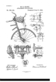
- FIG. 1 is a perspective view showing the devices attached to the forward part of a bi? cycle.
- Fig. 2 is an enlarged detail being a rear elevation of the devices for clamping to the handle-bar and handle-bar post and a .2 5 broken section of such bars and post.
- Fig. 3 is a perspective view showing the devices attached to the forward part of a bi? cycle.
- Fig. 1 is an end elevation of Fig.2.
- Fig. 2 is an enlarged detail, being an end View of the handle-bar post and showing the manner of applying the clip to said post.
- Fig. 5 is a detail showing the under side of the seat and manner of securing the parts that support the seat to it.
- Fig. 6 is a detail being a side elevation of Fig. 5 the dotted lines showing the front support for the seat in a position to be withdrawn from the seat.
- Fig. 7 is a detail being a side elevation of the devices for supporting the front part of the seat.
- Fig. 8 is a detail being a front elevation of Fig. 7.
- Fig.1 is an end elevation of Fig.2.
- Fig. 6 is a detail showing the under side of the seat and manner of securing the parts that support the seat to it.
- Fig. 6 is a detail being a side elevation of Fig. 5 the dotted lines showing the front support for the seat in a position to be
- Fig. 9 is an enlarged detail, being a side elevation of the coasters, or foot-rest, as attached to a section of the seat forks.
- Fig. 10 is an enlarged detail showing one end of the foot-rest with the bolt removed, and
- Fig. 11 is an enlarged detail, being a sectional View of Fig;
- a whole bicycle is not shown in the drawin gs, only enough-viz., the handle-bars, steering fork and head, and upper part of the front wheel to which the devices of this invention bicycle.
- the fork of thebicycle is designated by the lgettgr A, the post by B, and the handle-bar D .D is a bracketof metal, cast, forged, or madein any suitable manner and of-a form to have three bearing points on the handlebars and handle-bar post-viz., one bearing on the right handle-bar, and one on the left handle-bar and one on the h'endle-bar post; and a clip u is used intermediate between these three bearing points to draw the bearing points against the handle-bars and post.
- U-shaped clip to embrace the handle-bar post, and have the two ends of said clip pass through suitable holes in the bracket D D, and nuts on the ends of the clip to screw up against the bracket and bind it against the handle-bars and post.
- the clip a mightbe made in the form of a hook to comevonly part way around the post, and have only one end pass through the bracket D D, or a part might be cast, or otherwise formed on the bracket D D to come around the opposite side of the post and be'provided there with a set screw to push against the post to hold the bracket on.
- bracket D D I prefer to have all three bearing points on the bracket D D made to come on the handle-bars and post on the same side and the binding clip or device to come between these three points but they might be made to have the bearing points on the handle-bars on one side while the bearing point on the post was on the opposite side and the clip or binding device lower down on the post bringing the bearing point of the bracket on the post intermediate between the bearing points on the handle-bar and the clamping device or clip a.
- the upper ends a a, of the bracket D D are curved to come partly over the handle-bars to make the grip on the handle-bars more secure, and the bearing 0 on the post is made forked, or with a recess c to secure it in the proper position on the post.
- the bracketD D might be constructed in some other form, but I prefer the form shown as it will fit nearly any of the different makes of bicycles without interfering with the brakes.
- the seat rods E E are made first to have horizontal portions Eand E to come under the seat, the portion E being bent at nearly right angles to the portion E and to extend out beyond the edge of the seat near one front corner of the seat and there the rods are bent upward to form the portion E" and lastly outward and nearly horizontally to form the portion E and handle part, and a suitable handle it can be put on this 'part.
- the rear ends of the seat rods E E go into the holes D in the bracket D D and are secured there by the set screw D.
- the F is a seat and in this case is made flat and upholstered, but can be made in any other suitable manner.
- the bottom of the seat is a board, to which the upholstering is attached and is secured to the supporting rods E E by means of the plates 3 and G, which come over the rods E E opposite the seat-board F and are held in place and made to bind against the rods E E by means of suitable bolts passing through the plates and board.
- the plates 8 and G have suitable grooves on one side for the rods E E to go in.
- the plate G has at each end grooves to fit on both the portions E and E of the seat rods, and'when clamped on will hold the seat rods firmly in place and prevent them from turning or twisting.
- the lower part of this plate G has a hook e which is made to hook around the part II of the fork head II, as shown in Figs. 6, 7 and 8.
- This part II is made flat, with its upper edge adapted to fit in a groove in the lower side of the plate G when the fork-head His turned at nearly right angles to the plate, or hanging down from said plate and the hook 0 will prevent the fork'head II from withdrawing from the plate G when in this position, but when the fork-head is turned forward in the position shown by the dotted lines in Fig. 6, it can then be withdrawn from the plate G.
- the fork-head II is provided with suitable enlargements II" II on its lower corners which have holes to receive the forksI I and the set screws 72 n will secure the forks in place.
- the forksI I are made of spring wire, (similar to those in my Patent No.4.80,760,) bowed down at the lowerpart and have eyes formed on their lower ends to go over the coasters of the bicycle. To fix them in place on the bicycle the seat part is first put in place with the rear ends of the rods E E secured in the bracket D D; then the forks and fork-head II are placed in the position shown by the dotted lines in Fig. 6.
- the lower ends of the forks are then dropped down under the coasters of the bicycle, and should be so adjusted by the set screw 01 in the head II that the eyes of the forks I I will be below the coasters about two inches; then these eyes are sprung upward and outward over the coasters, (the coasters going through the eyes) and left resting on the coasters. In this manner the whole device, seat and forks, will be under tension with all looseness taken out and will ride empty over rough roads without rattling.
- the foot-rests, or coasters, J J are made in halves but could be united at their outer ends, each half is made nearly in the form of a Y and has a crease orgroove across the forked part to fit on the forks I I or A A.
- the bolt is first laid in the opening J of the fork of the step; then the halves of the step are placed one on each side of the fork it goes on and the bolt 70 tightened up.
- Two or more sets of holes D I) can be made in the bracket D D to admit of two or more devices being attached to the bracket at the same time, for instance, the seat as shown herein can be used and at the same time a parcel carrier or baby carrier can be set behind the handle-bars, or two parcel carriers can be used at the same time without a seat.
- a bracket for a bicycle having three bearing points, two to bear on the handle-bar on opposite sides of the handle-bar post and one to bear against the post, and a U-shaped clip to go around the post intermediate between the said three bearing points, the ends of the said clip passing through holes in the said bracket and provided with nuts suitable for clamping the said bracket to the handlebars and post, substantially as and for the purposes specified.
- the bracket D D having three bearing points to come against the handle-bar and post, the clip a for binding the bracket to the post and handle-bars and the holes D D and screws D D for receiving and holding bicycle attachments such as carriers, seats, 850., substantially as set forth.
- the bracket D D having its upper ends a a curved over the handlebar and its lower end 0 provided with a fork, or groove 0' to receive the post, and the clip 26 intermediate between the three points a a and c for binding the bracket to the post and handle-bars,
- the said bracket to receive and hold securely attachments such as carriers, seats, &c., substantially as shown.
- bracket D D In a childs seat for bicycles the bracket D D, clip to, seat F, and forks I I all arranged and for use substantially as specified.
- the rods E E for supporting the seat, the said rods having horizontal portions E E, upright or inclined portion E" and horizontal portion E for handles substantially as and for the purposes specified.
- a seat for bicycles having a support for its rear side on the handle-bar post and having a detachable support for its forward side, consisting of the rods I-I, adjustably connected to a head II, the head I-I adapted tobe hooked or hinged to the forward part of the seat in such a manner that when'the supporting rods II and head H are in a level or horizontal position, the head H can be withdrawn from the seat but when the rods I--I and head H are in a nearly vertical position the head H will be held securely to the forward part of the seat, substantially as and for the purposes specified.
- a front support for the seat consisting of a plate G constructed substantially as shown with a hook e adapted to hook into a head H thereby forming a detachable hinge connection to connect the seat to the supporting rods II, for the purposes specified.
Landscapes
- Engineering & Computer Science (AREA)
- Mechanical Engineering (AREA)
- Steering Devices For Bicycles And Motorcycles (AREA)
Description
(No Mo'de1.)1 '1 f r M. E. BLOOD.
ATTACHMENT FOR BIGYGLES.
' No. 521,132. Patented June 5, 1894.
V/ v I UNITED STATES PATENT OFFICE.
\ MAURICE E. BLOOD, OF KALAMAZOO, MICHIGAN, ASSIGNOR TO THE ATTACHM ENT FOR BlCYC LES.
SPECIFICATION forming part of Letters Patent No. 521,132, dated June 5, 1894.
' Applica ion filed October 10, 1392. Serial No. 448,433. on. model.)
To all whom it may concern.-
Be it known that I, MAURICE E. BLOOD, re siding at Kalamazo o, in the county of Kalamazoo, State of Michigan, have invented a 5 new and useful Improvement in Attachments port on the handle bars of a bicycle. I at-.
tain these objects by the devices illustrated in the accompanying drawings, in which- Figure 1 is a perspective view showing the devices attached to the forward part of a bi? cycle. Fig. 2 is an enlarged detail being a rear elevation of the devices for clamping to the handle-bar and handle-bar post and a .2 5 broken section of such bars and post. Fig. 3
is an end elevation of Fig.2. Fig. 4 is an enlarged detail, being an end View of the handle-bar post and showing the manner of applying the clip to said post. Fig. 5 is a detail showing the under side of the seat and manner of securing the parts that support the seat to it. Fig. 6 is a detail being a side elevation of Fig. 5 the dotted lines showing the front support for the seat in a position to be withdrawn from the seat. Fig. 7 is a detail being a side elevation of the devices for supporting the front part of the seat. Fig. 8 is a detail being a front elevation of Fig. 7. Fig.1
9 is an enlarged detail, being a side elevation of the coasters, or foot-rest, as attached to a section of the seat forks. Fig. 10 is an enlarged detail showing one end of the foot-rest with the bolt removed, and Fig. 11 is an enlarged detail, being a sectional View of Fig;
9 on line 1111.
A whole bicycle is not shown in the drawin gs, only enough-viz., the handle-bars, steering fork and head, and upper part of the front wheel to which the devices of this invention bicycle.
Similar letters refer to similar parts thro ughout the several views.
The fork of thebicycle is designated by the lgettgr A, the post by B, and the handle-bar D .D is a bracketof metal, cast, forged, or madein any suitable manner and of-a form to have three bearing points on the handlebars and handle-bar post-viz., one bearing on the right handle-bar, and one on the left handle-bar and one on the h'endle-bar post; and a clip u is used intermediate between these three bearing points to draw the bearing points against the handle-bars and post. I prefer to use a U-shaped clip to embrace the handle-bar post, and have the two ends of said clip pass through suitable holes in the bracket D D, and nuts on the ends of the clip to screw up against the bracket and bind it against the handle-bars and post. The clip a mightbe made in the form of a hook to comevonly part way around the post, and have only one end pass through the bracket D D, or a part might be cast, or otherwise formed on the bracket D D to come around the opposite side of the post and be'provided there with a set screw to push against the post to hold the bracket on. I prefer to have all three bearing points on the bracket D D made to come on the handle-bars and post on the same side and the binding clip or device to come between these three points but they might be made to have the bearing points on the handle-bars on one side while the bearing point on the post was on the opposite side and the clip or binding device lower down on the post bringing the bearing point of the bracket on the post intermediate between the bearing points on the handle-bar and the clamping device or clip a. The upper ends a a, of the bracket D D are curved to come partly over the handle-bars to make the grip on the handle-bars more secure, and the bearing 0 on the post is made forked, or with a recess c to secure it in the proper position on the post. The bracket D D is provided with holes D D to receive the seat rods E E or any other rods suitable for supporting car= riers and other attachments to thebicycle and the set screws D" D enter the holes D i D from one side to secure the rods in their place. The bracketD D might be constructed in some other form, but I prefer the form shown as it will fit nearly any of the different makes of bicycles without interfering with the brakes. The seat rods E E are made first to have horizontal portions Eand E to come under the seat, the portion E being bent at nearly right angles to the portion E and to extend out beyond the edge of the seat near one front corner of the seat and there the rods are bent upward to form the portion E" and lastly outward and nearly horizontally to form the portion E and handle part, and a suitable handle it can be put on this 'part.
The rear ends of the seat rods E E go into the holes D in the bracket D D and are secured there by the set screw D.
F is a seat and in this case is made flat and upholstered, but can be made in any other suitable manner. The bottom of the seat is a board, to which the upholstering is attached and is secured to the supporting rods E E by means of the plates 3 and G, which come over the rods E E opposite the seat-board F and are held in place and made to bind against the rods E E by means of suitable bolts passing through the plates and board. The plates 8 and G have suitable grooves on one side for the rods E E to go in. The plate G has at each end grooves to fit on both the portions E and E of the seat rods, and'when clamped on will hold the seat rods firmly in place and prevent them from turning or twisting. The lower part of this plate G has a hook e which is made to hook around the part II of the fork head II, as shown in Figs. 6, 7 and 8. This part II is made flat, with its upper edge adapted to fit in a groove in the lower side of the plate G when the fork-head His turned at nearly right angles to the plate, or hanging down from said plate and the hook 0 will prevent the fork'head II from withdrawing from the plate G when in this position, but when the fork-head is turned forward in the position shown by the dotted lines in Fig. 6, it can then be withdrawn from the plate G.
The fork-head II is provided with suitable enlargements II" II on its lower corners which have holes to receive the forksI I and the set screws 72 n will secure the forks in place.
The forksI I are made of spring wire, (similar to those in my Patent No.4.80,760,) bowed down at the lowerpart and have eyes formed on their lower ends to go over the coasters of the bicycle. To fix them in place on the bicycle the seat part is first put in place with the rear ends of the rods E E secured in the bracket D D; then the forks and fork-head II are placed in the position shown by the dotted lines in Fig. 6. The lower ends of the forks are then dropped down under the coasters of the bicycle, and should be so adjusted by the set screw 01 in the head II that the eyes of the forks I I will be below the coasters about two inches; then these eyes are sprung upward and outward over the coasters, (the coasters going through the eyes) and left resting on the coasters. In this manner the whole device, seat and forks, will be under tension with all looseness taken out and will ride empty over rough roads without rattling.
The foot-rests, or coasters, J J are made in halves but could be united at their outer ends, each half is made nearly in the form of a Y and has a crease orgroove across the forked part to fit on the forks I I or A A.
The bolt is first laid in the opening J of the fork of the step; then the halves of the step are placed one on each side of the fork it goes on and the bolt 70 tightened up.
Two or more sets of holes D I) can be made in the bracket D D to admit of two or more devices being attached to the bracket at the same time, for instance, the seat as shown herein can be used and at the same time a parcel carrier or baby carrier can be set behind the handle-bars, or two parcel carriers can be used at the same time without a seat.
I am aware that attachments for carriers have been made to have two hearings on the handle-bars and one on the post; some of these are only wires bent around without any clamping device while others are clamped or "bolted to the handle-bars but do not have any clamp that holds the bearing directly against the post. Such devices I do not claim.
The principal advantage in the manner in which I secure my bracket to the handle-bar and post is that one clamping device holds all three of the bearing points tight in their respective places, drawing one against the post as well as the other two against the hen die-bars, and holds the bracket so it can be used to support the load either in front or behind the handle-bars, which most of the other devices will not do.
What I claim as new, and desire to secure by Letters Patent, is-
1. A bracket for a bicycle, having three bearing points, two to bear on the handle-bar on opposite sides of the handle-bar post and one to bear against the post, and a U-shaped clip to go around the post intermediate between the said three bearing points, the ends of the said clip passing through holes in the said bracket and provided with nuts suitable for clamping the said bracket to the handlebars and post, substantially as and for the purposes specified.
2. The bracket D D having three bearing points to come against the handle-bar and post, the clip a for binding the bracket to the post and handle-bars and the holes D D and screws D D for receiving and holding bicycle attachments such as carriers, seats, 850., substantially as set forth.
3. The bracket D D having its upper ends a a curved over the handlebar and its lower end 0 provided with a fork, or groove 0' to receive the post, and the clip 26 intermediate between the three points a a and c for binding the bracket to the post and handle-bars,
tog
the said bracket to receive and hold securely attachments such as carriers, seats, &c., substantially as shown.
4. In a childs seat for bicycles the bracket D D, clip to, seat F, and forks I I all arranged and for use substantially as specified.
5. In a childs seat for bicycles the rods E E for supporting the seat, the said rods having horizontal portions E E, upright or inclined portion E" and horizontal portion E for handles substantially as and for the purposes specified.
6. A seat for bicycles having a support for its rear side on the handle-bar post and having a detachable support for its forward side, consisting of the rods I-I, adjustably connected to a head II, the head I-I adapted tobe hooked or hinged to the forward part of the seat in such a manner that when'the supporting rods II and head H are in a level or horizontal position, the head H can be withdrawn from the seat but when the rods I--I and head H are in a nearly vertical position the head H will be held securely to the forward part of the seat, substantially as and for the purposes specified.
7. In a seat for bicycles a support on the handle-bar post for the rear side of the seat, the front part of the seat being supported on rods extending up from the front fork A, in
combination with the head H and plate G adapted to be hooked or hinged together, substantially as shown.
8. In a seat for bicycles a front support for the seat consisting of a plate G constructed substantially as shown with a hook e adapted to hook into a head H thereby forming a detachable hinge connection to connect the seat to the supporting rods II, for the purposes specified.
9. In a seat for bicycles the rods E-E for supporting the seat, the bracketD-D for receiving and holding the rear ends of the rods MAURICE E. BLOOD Witnesses:
CLARENCE O. BLOOD, HATTIE E. CARD.
Publications (1)
| Publication Number | Publication Date |
|---|---|
| US521132A true US521132A (en) | 1894-06-05 |
Family
ID=2589930
Family Applications (1)
| Application Number | Title | Priority Date | Filing Date |
|---|---|---|---|
| US521132D Expired - Lifetime US521132A (en) | Maurice e |
Country Status (1)
| Country | Link |
|---|---|
| US (1) | US521132A (en) |
-
0
- US US521132D patent/US521132A/en not_active Expired - Lifetime
Similar Documents
| Publication | Publication Date | Title |
|---|---|---|
| US20090289091A1 (en) | Cargo Rack for Cycles and Scooters | |
| US556951A (en) | And joseph ii | |
| US579584A (en) | Bicycle-hanger | |
| US3414223A (en) | Basket attachment for bicycles | |
| US521132A (en) | Maurice e | |
| US7261227B2 (en) | Luggage rack apparatus | |
| US843094A (en) | Combined seat and luggage-carrier for bicycles. | |
| US574628A (en) | Harry c | |
| US481890A (en) | blood | |
| US436403A (en) | Attachment for bicycles | |
| US652325A (en) | Lunch-basket for bicycles. | |
| US460031A (en) | Seat attachment for bicycles | |
| US579514A (en) | Seat for bicycles | |
| US571302A (en) | Bicycle | |
| US731207A (en) | Motor-cycle. | |
| US560187A (en) | Maurice e | |
| US582334A (en) | August zintgraff | |
| US550501A (en) | Half to henry a | |
| US477042A (en) | Irving calver | |
| US2354881A (en) | Auxiliary bicycle seat | |
| US1164207A (en) | Tandem seat for bicycles or motor-cycles. | |
| US2544963A (en) | Auxiliary load-carrying attachment for tricycles, velocipedes, and the like | |
| US611905A (en) | Bicycle luggage-carrier | |
| US523115A (en) | Bicycle-saddle | |
| US704885A (en) | Combined mud-guard, supplemental seat, and parcel-holder for bicycles. |