US5207106A - Method and apparatus for testing optical fibers - Google Patents
Method and apparatus for testing optical fibers Download PDFInfo
- Publication number
- US5207106A US5207106A US07/787,173 US78717391A US5207106A US 5207106 A US5207106 A US 5207106A US 78717391 A US78717391 A US 78717391A US 5207106 A US5207106 A US 5207106A
- Authority
- US
- United States
- Prior art keywords
- projectile
- optical fiber
- barrel
- payout
- closure
- Prior art date
- Legal status (The legal status is an assumption and is not a legal conclusion. Google has not performed a legal analysis and makes no representation as to the accuracy of the status listed.)
- Expired - Lifetime
Links
- 239000013307 optical fiber Substances 0.000 title claims abstract description 81
- 238000012360 testing method Methods 0.000 title claims abstract description 24
- 238000000034 method Methods 0.000 title claims description 7
- 239000002360 explosive Substances 0.000 claims description 7
- 239000008188 pellet Substances 0.000 claims description 6
- 238000010998 test method Methods 0.000 claims description 3
- 238000004891 communication Methods 0.000 claims description 2
- 239000007789 gas Substances 0.000 description 20
- 230000001070 adhesive effect Effects 0.000 description 13
- 239000000853 adhesive Substances 0.000 description 12
- 238000013459 approach Methods 0.000 description 11
- 239000003365 glass fiber Substances 0.000 description 10
- 239000000835 fiber Substances 0.000 description 7
- 238000004804 winding Methods 0.000 description 6
- 230000000694 effects Effects 0.000 description 5
- 229910000831 Steel Inorganic materials 0.000 description 4
- 230000008878 coupling Effects 0.000 description 4
- 238000010168 coupling process Methods 0.000 description 4
- 238000005859 coupling reaction Methods 0.000 description 4
- 239000010959 steel Substances 0.000 description 4
- IJGRMHOSHXDMSA-UHFFFAOYSA-N Atomic nitrogen Chemical compound N#N IJGRMHOSHXDMSA-UHFFFAOYSA-N 0.000 description 2
- 239000004677 Nylon Substances 0.000 description 2
- VYPSYNLAJGMNEJ-UHFFFAOYSA-N Silicium dioxide Chemical compound O=[Si]=O VYPSYNLAJGMNEJ-UHFFFAOYSA-N 0.000 description 2
- 230000005540 biological transmission Effects 0.000 description 2
- 230000007547 defect Effects 0.000 description 2
- 239000011521 glass Substances 0.000 description 2
- 238000005259 measurement Methods 0.000 description 2
- 229920001778 nylon Polymers 0.000 description 2
- 230000003287 optical effect Effects 0.000 description 2
- 229920000642 polymer Polymers 0.000 description 2
- 238000002360 preparation method Methods 0.000 description 2
- MWCLLHOVUTZFKS-UHFFFAOYSA-N Methyl cyanoacrylate Chemical compound COC(=O)C(=C)C#N MWCLLHOVUTZFKS-UHFFFAOYSA-N 0.000 description 1
- 230000001133 acceleration Effects 0.000 description 1
- 239000011248 coating agent Substances 0.000 description 1
- 238000000576 coating method Methods 0.000 description 1
- 230000001419 dependent effect Effects 0.000 description 1
- 238000005474 detonation Methods 0.000 description 1
- 230000007613 environmental effect Effects 0.000 description 1
- 238000009472 formulation Methods 0.000 description 1
- 239000003721 gunpowder Substances 0.000 description 1
- 238000011835 investigation Methods 0.000 description 1
- 239000000203 mixture Substances 0.000 description 1
- 238000012986 modification Methods 0.000 description 1
- 230000004048 modification Effects 0.000 description 1
- 229910052757 nitrogen Inorganic materials 0.000 description 1
- 239000005304 optical glass Substances 0.000 description 1
- 238000012545 processing Methods 0.000 description 1
- 230000001105 regulatory effect Effects 0.000 description 1
- 238000006748 scratching Methods 0.000 description 1
- 230000002393 scratching effect Effects 0.000 description 1
- 239000000377 silicon dioxide Substances 0.000 description 1
- 235000012239 silicon dioxide Nutrition 0.000 description 1
- 230000003068 static effect Effects 0.000 description 1
- 239000000126 substance Substances 0.000 description 1
Images


Classifications
-
- G—PHYSICS
- G01—MEASURING; TESTING
- G01N—INVESTIGATING OR ANALYSING MATERIALS BY DETERMINING THEIR CHEMICAL OR PHYSICAL PROPERTIES
- G01N3/00—Investigating strength properties of solid materials by application of mechanical stress
- G01N3/26—Investigating twisting or coiling properties
-
- G—PHYSICS
- G01—MEASURING; TESTING
- G01M—TESTING STATIC OR DYNAMIC BALANCE OF MACHINES OR STRUCTURES; TESTING OF STRUCTURES OR APPARATUS, NOT OTHERWISE PROVIDED FOR
- G01M11/00—Testing of optical apparatus; Testing structures by optical methods not otherwise provided for
- G01M11/08—Testing mechanical properties
- G01M11/088—Testing mechanical properties of optical fibres; Mechanical features associated with the optical testing of optical fibres
-
- G—PHYSICS
- G01—MEASURING; TESTING
- G01N—INVESTIGATING OR ANALYSING MATERIALS BY DETERMINING THEIR CHEMICAL OR PHYSICAL PROPERTIES
- G01N2203/00—Investigating strength properties of solid materials by application of mechanical stress
- G01N2203/003—Generation of the force
- G01N2203/0055—Generation of the force using mechanical waves, e.g. acoustic
-
- G—PHYSICS
- G01—MEASURING; TESTING
- G01N—INVESTIGATING OR ANALYSING MATERIALS BY DETERMINING THEIR CHEMICAL OR PHYSICAL PROPERTIES
- G01N2203/00—Investigating strength properties of solid materials by application of mechanical stress
- G01N2203/02—Details not specific for a particular testing method
- G01N2203/026—Specifications of the specimen
- G01N2203/0262—Shape of the specimen
- G01N2203/0278—Thin specimens
-
- G—PHYSICS
- G01—MEASURING; TESTING
- G01N—INVESTIGATING OR ANALYSING MATERIALS BY DETERMINING THEIR CHEMICAL OR PHYSICAL PROPERTIES
- G01N33/00—Investigating or analysing materials by specific methods not covered by groups G01N1/00 - G01N31/00
- G01N33/38—Concrete; Lime; Mortar; Gypsum; Bricks; Ceramics; Glass
- G01N33/386—Glass
Definitions
- This invention relates to optical fibers, and, more particularly, to a method of testing the payout of an optical fiber from a support upon which it is wound.
- Optical fibers for information transmission are strands of glass fiber processed so that light transmitted through the fiber is subject to total internal reflection. A large fraction of the incident intensity of light directed into the glass fiber is received at the other end of the fiber, even though the glass fiber may be many thousands of meters long.
- Optical-quality glass fibers have shown great promise in communications applications, because a high density of information may be carried along the glass fiber and because the quality of the signal is less subject to external interferences of various types than are electrical signals carried on metallic wires.
- the glass fibers are light in weight and made from a plentiful substance, silicon dioxide.
- the glass fibers are fabricated by preparing a preform of glasses of the two different optical indices of refraction, one inside the other, and processing the preform to a fiber.
- the optical glass fiber is coated with a polymer layer termed a buffer to protect the glass from scratching or other damage, and the resulting coated glass fiber is generally termed an "optical fiber" in the art.
- a polymer layer termed a buffer to protect the glass from scratching or other damage
- the resulting coated glass fiber is generally termed an "optical fiber” in the art.
- the diameter of the glass fiber is about 125 micrometers
- the diameter of the glass fiber plus the polymer buffer (the optical fiber) is about 250 micrometers (approximately 0.010 inches).
- the optical fiber is wound onto a cylindrical or slightly tapered conical bobbin with many turns adjacent to each other in a side by side fashion. After one layer is complete, another layer of fiber is carefully laid on top of the first layer, and so on.
- the final assembly of the bobbin and the wound layers of optical fiber is termed a canister, and the mass of wound optical fiber is termed the fiber pack.
- the optical fiber is payed out from the canister in a direction generally parallel to the axis of the cylinder.
- the preparation of a canister demands great care and precision in winding of the optical fiber.
- the payout velocity of the optical fiber may be as high as several hundred to a thousand meters per second. If any snags, uneven stresses, or other irregularities are present, they can cause the optical fiber to snarl and/or break.
- One technique to avoid irregularities in the fiber pack is to utilize an adhesive on the optical fiber to hold each layer securely in place as the next layer is laid upon it. In one approach, a light coating of the adhesive is sprayed over a layer after it is wound onto the bobbin, prior to winding the next layer. In others, the bobbin may be dipped into a bath or the adhesive may be pre-applied to the optical fiber, for example.
- the smooth payout of the optical fiber from the canister is dependent upon a number of factors, including the type and amount of adhesive, the winding tension of the optical fiber as it is wound upon the bobbin, the size and regularity of the optical fiber, and the rate of payout which is often over 300 meters per second.
- the rate of payout which is often over 300 meters per second.
- the present invention provides a method and apparatus for testing the payout of optical fibers from a support.
- Very short lengths of optical fiber may be used to assess the effects of changes in adhesive, structure of the optical fiber, winding parameters, payout parameters, and other variables.
- the testing approach achieves payout rates comparable with those of actual service, using very little optical fiber and a simulated bobbin support structure. As a result, much more extensive and rigorous experimental investigation of parametric variations is possible than could be achieved with the more expensive prior testing approaches.
- a method of testing an optical fiber comprises mounting the optical fiber on a payout support with an unsupported end extending from the support, attaching the unsupported end of the optical fiber to a projectile, and propelling the projectile by contacting an expanding volume of pressurized gas to the projectile, so that the supported portion of the optical fiber is separated from the payout support.
- a length of the optical fiber is wound upon a support, which is preferably a hollow body of revolution such as a cylinder or a frustum of a cone.
- a free end is attached to the rear end of the projectile, which is then driven forwardly by expanding gas pressure at a velocity of hundreds of meters per second, comparable with the actual payout rate of the optical fiber in service. This velocity is reached so quickly that only a few meters of optical fiber is required to achieve usable test results.
- apparatus for testing an optical fiber comprises a projectile having an optical fiber attachment point on a rearwardly facing end.
- a pneumatic gun means receives and propels the projectile.
- the pneumatic gun means includes a barrel that receives the projectile therein, closure means on the rearward end of the barrel for containing a pressurized gas and for permitting an optical fiber to pass into the barrel, and means for pressurizing the portion of the interior of the barrel rearwardly of the projectile when it is received within the barrel.
- the projectile is accelerated by expanding gas in the barrel of a gun-like instrument.
- the expanding gas can be provided by any convenient approach, such as the detonation of an explosive charge or the release of a high static gas pressure.
- the velocity of the projectile is well controlled and reproducible, and may be readily measured.
- the optical fiber is instrumented as necessary, and the optical fiber may be recovered and physically examined after the payout test is complete.
- FIG. 1 is a schematic view of an optical fiber payout test apparatus in operation
- FIG. 2 is a side sectional view of a preferred pneumatic gun for pulling the optical fiber from its support;
- FIG. 3 is an enlarged side elevational view of a preferred form of a projectile used in the pneumatic gun of FIG. 2;
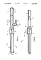
- FIG. 4 is an enlarged side sectional view of a detail of FIG. 2, illustrating the latching mechanism while engaged to the projectile;
- FIG. 5 is a view comparable to that of FIG. 4, except after disengagement of the latch from the projectile;
- FIG. 6 is a side sectional view of an alternative embodiment using an explosive charge.
- FIG. 1 illustrates an apparatus 20 for conducting a payout test of an optical fiber 22.
- the optical fiber 22 is wound upon a payout support 24, which is illustrated as a preferred hollow frustum of a cone.
- This support 24 is a slightly tapered hollow cylinder, with the amount of taper typically from about 2 to about 5 degrees.
- a number of turns of optical fiber 22 are would side-by-side on the support 24, with a number of layers wound overlying each other.
- An adhesive is typically applied to each layer as it is completed, and before the next layer is applied.
- Variables which are most often under study are the type of adhesive, amount of adhesive, winding tension, effect of winding defects, optical transmission during payout, environmental effects, etc., but the use of the invention is not limited by the type of information to be gathered or by the physical geometry of the payout support.
- a free or unsupported end 26 of the optical fiber 22 extends from the support 24 and is attached to a rearward end 28 of a projectile 30, preferably with an adhesive.
- the projectile 30 is accelerated by a device 32 that uses the expansion of pressurized gas to drive the projectile 30. Two preferred types of devices 32 will be described subsequently.
- the projectile 30 is stopped after a predetermined length of travel, preferably by a catching net 34.
- the velocity of the projectile 30, and thence the rate of dispensing of the optical fiber from the support 24, may be measured by any convenient approach. In one technique, the velocity is measured by a trap 36 in which the projectile 30 breaks light beams produced by sources 37 and received by photocells 38 at the beginning and end of the trap 36 as it passes.
- the time to pass the length of the trap is measured by a chronograph 39.
- the average velocity is the ratio of the distance between the photocells 38, divided by the elapsed measured time to pass that distance.
- FIG. 2 A preferred form of the device 32, a pneumatic gun 40, is illustrated in FIG. 2.
- a preferred projectile 42 for use with the pneumatic gun 40 is illustrated in FIG. 3.
- the pneumatic gun 40 includes a barrel 44, which is an elongated hollow cylinder dimensioned to receive the projectile 42 and open at both ends.
- the barrel 44 is supported within a pressure housing 46.
- the volume between the outer diameter of the barrel 44 and the inner diameter of the pressure housing 46 serves as a reservoir 48 for holding pressurized gas, as will be described in more detail subsequently. Pressurized gas is provided to the reservoir 48 through a communicating line 49.
- a closure 50 At one end of the barrel and pressure housing is a closure 50, which includes an elongated cylindrical closure housing 52 joined to the pressure housing 46 by a removable coupling 54.
- the closure 50 has a back wall 56 with a bore 58 therein, the bore 58 being generally concentric with the axis of the barrel 44.
- the optical fiber 22 is threaded through the bore 58 and attached at its unsupported end 26 to the projectile 42.
- the projectile 42 is loaded into the end of the barrel 44 with the coupling 54 and closure 50 removed.
- the projectile 42 is engaged by a latching mechanism 60, which holds it in a preselected position until released.
- the coupling 54 and closure 50 are fastened into position on the rearward end of the pressure housing 46.
- the support 24 upon which the balance of the optical fiber 22 is wound is fastened to a base (not shown), and the apparatus 20 adjusted so that the optical fiber 24 is taut or slightly drooping.
- a gas pressure typically about 200 pounds per square inch or less, is introduced into the gas reservoir 48 through the gas line 49 from an external source such as a regulated gas bottle.
- the preferred gas is nitrogen or air, but any gas that does not interfere with the testing can be used.
- the pneumatic gun 40 is fired by pulling a trigger wire 64 that extends from the latching mechanism 60 to the exterior of the pneumatic gun 40.
- the projectile 42 is driven forward (to the right in the view of FIGS. 1 and 2) and out the open end of the barrel 44.
- the optical fiber 22 is rapidly payed out from the support 24.
- the average velocity of the projectile 42 which is the payout velocity of the optical fiber 22, is measured as the projectile 42 passes through the trap 36. After a preselected distance of travel, the projectile 42 is caught in the catching net 34, and the test is complete. Data gathered during the test is then analyzed.
- FIG. 3 illustrates the projectile 42 in greater detail.
- the projectile 42 includes a generally cylindrical pellet 66 and a shaft 68 of smaller diameter extending rearwardly therefrom.
- the pellet 66 is preferably, although not necessarily, made of machined nylon.
- the pellet 66 is dimensioned to fit within the barrel 44 and to slide smoothly therein.
- a piece of high strength steel wire 70 extends transversely through the shaft 68 and serves as an engagement with the latching mechanism 60.
- At the back end of the shaft 68 is a flat 72 machined therein.
- the optical fiber 22 is fastened to the projectile 42 on this flat 72, preferably by using an adhesive such as a cyano-acrylate.
- the latching mechanism 60 which engages the projectile 42 and holds it in place until release is shown in FIG. 4 in the latched or engaged position, and in FIG. 5 in the unlatched or released position.
- the latching mechanism 60 includes a latch 74 pivotably mounted to the pressure housing 46, and a latch release 76 also pivotably mounted to the pressure housing 46 at another location.
- a first notch 78 on the latch 74 engages the high strength wire 70 extending transversely from the projectile 42 in the latched position of FIG. 4.
- a second notch 80 is contacted by the latch release 76. In the latched position, the latch release 76 maintains the first notch 78 against the wire 70, so that the projectile 42 is restrained against any movement.
- the latch release 76 pivots clockwise in the view of FIG. 5, releasing the latch 74 to move clockwise in the view of FIG. 5.
- the projectile 42 no longer constrained against movement, moves to the right in the view of FIG. 5, propelled by the gas pressure in the reservoir 48.
- the barrel 44 is a smooth steel tube having an inside diameter of about 0.4-0.5 inches and a length of about 25 to 48 inches.
- the pressure housing 46 has an inside diameter of about 11/2 to 2 inches.
- the diameter of the bore 58 is about 0.040 inches for an optical fiber of diameter about 0.010 inches.
- the projectile 42 is made light in weight to permit rapid acceleration to high speed.
- the projectile 42 is made of a steel shaft 68, a nylon projectile body, and a steel wire 70.
- the total weight of the projectile is typically about 1 gram.
- the outer diameter of the projectile 42 is dimensioned to be about 0.0005 inches smaller than the inside diameter of the barrel 44.
- the operating pressure is typically in the range of about 60-140 pounds per square inch, depending upon the desired velocity to be achieved by the projectile.
- An apparatus 90 includes a barrel 44, coupling 54, closure 50, and bore 58 through the closure like that described previously.
- a projectile 92 includes a casing 94 and a mass 96, with the optical fiber 22 attached to the mass 96.
- the interior 98 of the casing is filled with an explosive such as gunpowder.
- a pin mechanism 100 is positioned immediately rearwardly of the casing 94, and activated by an external trigger 102. When the trigger 102 is pulled, the mechanism 100 operates to ignite the explosive, driving the mass 96 forwardly and rapidly moving the optical fiber 22 to the right in the view of FIG. 5.
- the first embodiment using a pneumatic gun operated by air pressure was used to propel the projectile at velocities of from 600 to 767 feet per second.
- the second embodiment using an explosive charge to generate the expanding gas was used to propel the projectile at velocities of from 425 to 1035 feet per second.
Landscapes
- Chemical & Material Sciences (AREA)
- Analytical Chemistry (AREA)
- Physics & Mathematics (AREA)
- General Physics & Mathematics (AREA)
- Health & Medical Sciences (AREA)
- Life Sciences & Earth Sciences (AREA)
- Biochemistry (AREA)
- General Health & Medical Sciences (AREA)
- Immunology (AREA)
- Pathology (AREA)
- Investigating Strength Of Materials By Application Of Mechanical Stress (AREA)
Abstract
Description
Claims (16)
Priority Applications (1)
| Application Number | Priority Date | Filing Date | Title |
|---|---|---|---|
| US07/787,173 US5207106A (en) | 1991-11-04 | 1991-11-04 | Method and apparatus for testing optical fibers |
Applications Claiming Priority (1)
| Application Number | Priority Date | Filing Date | Title |
|---|---|---|---|
| US07/787,173 US5207106A (en) | 1991-11-04 | 1991-11-04 | Method and apparatus for testing optical fibers |
Publications (1)
| Publication Number | Publication Date |
|---|---|
| US5207106A true US5207106A (en) | 1993-05-04 |
Family
ID=25140633
Family Applications (1)
| Application Number | Title | Priority Date | Filing Date |
|---|---|---|---|
| US07/787,173 Expired - Lifetime US5207106A (en) | 1991-11-04 | 1991-11-04 | Method and apparatus for testing optical fibers |
Country Status (1)
| Country | Link |
|---|---|
| US (1) | US5207106A (en) |
Cited By (5)
| Publication number | Priority date | Publication date | Assignee | Title |
|---|---|---|---|---|
| US5322997A (en) * | 1993-07-06 | 1994-06-21 | The United States Of America As Represented By The Secretary Of The Navy | Optic fiber payout test apparatus having a projectile track system with dual rails |
| US5456103A (en) * | 1992-07-20 | 1995-10-10 | State Of Israel, Ministry Of Defense, Armament Development Authority | Measurement of fiber drift |
| US20080083288A1 (en) * | 2006-10-04 | 2008-04-10 | Gregory Scott Glaesemann | Method and apparatus for proof testing a sheet of brittle material |
| US20140063840A1 (en) * | 2012-08-31 | 2014-03-06 | Boe Technology Group Co., Ltd. | Light source structure for optical fiber display device and optical fiber display device |
| CN113607220A (en) * | 2021-08-26 | 2021-11-05 | 四川航天系统工程研究所 | Test device for testing high-speed expansion of cable |
Citations (3)
| Publication number | Priority date | Publication date | Assignee | Title |
|---|---|---|---|---|
| US229058A (en) * | 1880-06-22 | spencer | ||
| US4077349A (en) * | 1976-06-14 | 1978-03-07 | Paul William A | Line boy |
| US5103678A (en) * | 1991-05-06 | 1992-04-14 | The United States Of America As Represented By The Secretary Of The Navy | Fiber peel force measuring apparatus |
-
1991
- 1991-11-04 US US07/787,173 patent/US5207106A/en not_active Expired - Lifetime
Patent Citations (3)
| Publication number | Priority date | Publication date | Assignee | Title |
|---|---|---|---|---|
| US229058A (en) * | 1880-06-22 | spencer | ||
| US4077349A (en) * | 1976-06-14 | 1978-03-07 | Paul William A | Line boy |
| US5103678A (en) * | 1991-05-06 | 1992-04-14 | The United States Of America As Represented By The Secretary Of The Navy | Fiber peel force measuring apparatus |
Cited By (7)
| Publication number | Priority date | Publication date | Assignee | Title |
|---|---|---|---|---|
| US5456103A (en) * | 1992-07-20 | 1995-10-10 | State Of Israel, Ministry Of Defense, Armament Development Authority | Measurement of fiber drift |
| US5322997A (en) * | 1993-07-06 | 1994-06-21 | The United States Of America As Represented By The Secretary Of The Navy | Optic fiber payout test apparatus having a projectile track system with dual rails |
| US20080083288A1 (en) * | 2006-10-04 | 2008-04-10 | Gregory Scott Glaesemann | Method and apparatus for proof testing a sheet of brittle material |
| US7461564B2 (en) | 2006-10-04 | 2008-12-09 | Corning Incorporated | Method and apparatus for proof testing a sheet of brittle material |
| US20140063840A1 (en) * | 2012-08-31 | 2014-03-06 | Boe Technology Group Co., Ltd. | Light source structure for optical fiber display device and optical fiber display device |
| US8807815B2 (en) * | 2012-08-31 | 2014-08-19 | Boe Technology Group Co., Ltd. | Light source structure for optical fiber display device and optical fiber display device |
| CN113607220A (en) * | 2021-08-26 | 2021-11-05 | 四川航天系统工程研究所 | Test device for testing high-speed expansion of cable |
Similar Documents
| Publication | Publication Date | Title |
|---|---|---|
| CN102135480B (en) | System and method for performing impact loading on micro test piece and measuring dynamic mechanical property | |
| EP0483661B1 (en) | Method for measuring actual load at failure of optical fiber | |
| JPH03503937A (en) | Optical fiber buffer inspection equipment | |
| US5207106A (en) | Method and apparatus for testing optical fibers | |
| CN107421706B (en) | Diversified test platform for dynamic characteristics of target in strong impact environment | |
| US5167382A (en) | Inside payout optical fiber canister having reduced adhesive in the optical fiber pack | |
| Stone et al. | Stress-Strain Relationships in Yarns Subjected to Rapid Impact Loading: Part I: Equipment, Testing Procedure, and Typical Results1, 2 | |
| CA2015023C (en) | Method and apparatus for flight payout testing of optical fibers | |
| JPH02500859A (en) | Duct inspection method | |
| US4271761A (en) | High acceleration cable deployment system | |
| US6393923B1 (en) | Dynamic bendloss measuring device | |
| US5351553A (en) | High rate flywheel tensile testing apparatus for viscoelastic materials | |
| US4911027A (en) | Method and apparatus for optical fiber/wire payout simulation | |
| US4940891A (en) | Automated system for measuring the strength of optical fibers | |
| CA2056595C (en) | Payout tester of a filament dispenser and method therefor | |
| US5179612A (en) | Optical fiber canister with ablative coating | |
| KR101735604B1 (en) | Equipment for testing reliability of unwinding behavior of optical fiber cable for communication | |
| EP0434281B1 (en) | Apparatus and method for determining elastic properties of optical fiber by contact area measurement | |
| Hamdan et al. | A crossbow system for high-strain-rate mechanical testing | |
| US5322997A (en) | Optic fiber payout test apparatus having a projectile track system with dual rails | |
| US5110061A (en) | Pneumatic reel fiber pay out system | |
| CN1606688A (en) | Method of testing optical fibers | |
| Tzeng et al. | Dynamic compressive properties of composites at interior ballistic rates of loading—Experimental method | |
| CN114777816B (en) | Method and system for early warning and inhibiting hollow microstructure fiber winding breakpoint | |
| SU847151A1 (en) | Method of inducing pulse loads in investigated specimen |
Legal Events
| Date | Code | Title | Description |
|---|---|---|---|
| AS | Assignment |
Owner name: HUGHES AIRCRAFT COMPANY, CALIFORNIA Free format text: ASSIGNMENT OF ASSIGNORS INTEREST.;ASSIGNORS:SCHWIDER, ALFRED M.;WYSOCKI, JOSEPH A.;REEL/FRAME:005914/0619;SIGNING DATES FROM 19911015 TO 19911028 |
|
| STCF | Information on status: patent grant |
Free format text: PATENTED CASE |
|
| FEPP | Fee payment procedure |
Free format text: PAYOR NUMBER ASSIGNED (ORIGINAL EVENT CODE: ASPN); ENTITY STATUS OF PATENT OWNER: LARGE ENTITY |
|
| REMI | Maintenance fee reminder mailed | ||
| FPAY | Fee payment |
Year of fee payment: 4 |
|
| SULP | Surcharge for late payment | ||
| AS | Assignment |
Owner name: HUGHES ELECTRONICS CORPORATION, CALIFORNIA Free format text: ASSIGNMENT OF ASSIGNORS INTEREST;ASSIGNOR:HE HOLDINGS INC., HUGHES ELECTRONICS FORMERLY KNOWN AS HUGHES AIRCRAFT COMPANY;REEL/FRAME:009350/0366 Effective date: 19971217 |
|
| FEPP | Fee payment procedure |
Free format text: PAYOR NUMBER ASSIGNED (ORIGINAL EVENT CODE: ASPN); ENTITY STATUS OF PATENT OWNER: LARGE ENTITY Free format text: PAYER NUMBER DE-ASSIGNED (ORIGINAL EVENT CODE: RMPN); ENTITY STATUS OF PATENT OWNER: LARGE ENTITY |
|
| FPAY | Fee payment |
Year of fee payment: 8 |
|
| FPAY | Fee payment |
Year of fee payment: 12 |