US5205129A - Apparatus for freezing and dispensing semi-frozen food products having dual freezing chambers and method - Google Patents
Apparatus for freezing and dispensing semi-frozen food products having dual freezing chambers and method Download PDFInfo
- Publication number
- US5205129A US5205129A US07/875,836 US87583692A US5205129A US 5205129 A US5205129 A US 5205129A US 87583692 A US87583692 A US 87583692A US 5205129 A US5205129 A US 5205129A
- Authority
- US
- United States
- Prior art keywords
- product
- freezing
- duty cycle
- chambers
- freezing chambers
- Prior art date
- Legal status (The legal status is an assumption and is not a legal conclusion. Google has not performed a legal analysis and makes no representation as to the accuracy of the status listed.)
- Expired - Lifetime
Links
- 230000008014 freezing Effects 0.000 title claims abstract description 225
- 238000007710 freezing Methods 0.000 title claims abstract description 225
- 238000000034 method Methods 0.000 title claims description 16
- 235000013305 food Nutrition 0.000 title abstract description 10
- 230000009977 dual effect Effects 0.000 title description 4
- 239000003507 refrigerant Substances 0.000 claims abstract description 58
- 230000000737 periodic effect Effects 0.000 claims abstract description 24
- 238000005057 refrigeration Methods 0.000 claims description 14
- 230000005540 biological transmission Effects 0.000 claims description 4
- 230000004044 response Effects 0.000 claims description 3
- 238000010438 heat treatment Methods 0.000 description 4
- 238000010586 diagram Methods 0.000 description 3
- 239000007788 liquid Substances 0.000 description 3
- IJGRMHOSHXDMSA-UHFFFAOYSA-N Atomic nitrogen Chemical compound N#N IJGRMHOSHXDMSA-UHFFFAOYSA-N 0.000 description 2
- CURLTUGMZLYLDI-UHFFFAOYSA-N Carbon dioxide Chemical compound O=C=O CURLTUGMZLYLDI-UHFFFAOYSA-N 0.000 description 2
- 239000013256 coordination polymer Substances 0.000 description 2
- 239000007789 gas Substances 0.000 description 2
- 239000004615 ingredient Substances 0.000 description 2
- 239000000203 mixture Substances 0.000 description 2
- 230000000063 preceeding effect Effects 0.000 description 2
- 239000003570 air Substances 0.000 description 1
- 235000013361 beverage Nutrition 0.000 description 1
- 230000000903 blocking effect Effects 0.000 description 1
- 229910002092 carbon dioxide Inorganic materials 0.000 description 1
- 239000001569 carbon dioxide Substances 0.000 description 1
- 230000008878 coupling Effects 0.000 description 1
- 238000010168 coupling process Methods 0.000 description 1
- 238000005859 coupling reaction Methods 0.000 description 1
- 230000003247 decreasing effect Effects 0.000 description 1
- 230000001419 dependent effect Effects 0.000 description 1
- 230000000694 effects Effects 0.000 description 1
- 239000000796 flavoring agent Substances 0.000 description 1
- 235000019634 flavors Nutrition 0.000 description 1
- 235000013611 frozen food Nutrition 0.000 description 1
- 230000006870 function Effects 0.000 description 1
- 235000015243 ice cream Nutrition 0.000 description 1
- 238000002955 isolation Methods 0.000 description 1
- 229910052757 nitrogen Inorganic materials 0.000 description 1
- 239000002245 particle Substances 0.000 description 1
- 239000000725 suspension Substances 0.000 description 1
Images


Classifications
-
- G—PHYSICS
- G07—CHECKING-DEVICES
- G07F—COIN-FREED OR LIKE APPARATUS
- G07F17/00—Coin-freed apparatus for hiring articles; Coin-freed facilities or services
- G07F17/0064—Coin-freed apparatus for hiring articles; Coin-freed facilities or services for processing of food articles
- G07F17/0071—Food articles which need to be processed for dispensing in a cold condition, e.g. ice and ice cream
-
- A—HUMAN NECESSITIES
- A23—FOODS OR FOODSTUFFS; TREATMENT THEREOF, NOT COVERED BY OTHER CLASSES
- A23G—COCOA; COCOA PRODUCTS, e.g. CHOCOLATE; SUBSTITUTES FOR COCOA OR COCOA PRODUCTS; CONFECTIONERY; CHEWING GUM; ICE-CREAM; PREPARATION THEREOF
- A23G9/00—Frozen sweets, e.g. ice confectionery, ice-cream; Mixtures therefor
- A23G9/04—Production of frozen sweets, e.g. ice-cream
- A23G9/14—Continuous production
- A23G9/16—Continuous production the products being within a cooled chamber, e.g. drum
- A23G9/163—Continuous production the products being within a cooled chamber, e.g. drum with intermittent operation
-
- A—HUMAN NECESSITIES
- A23—FOODS OR FOODSTUFFS; TREATMENT THEREOF, NOT COVERED BY OTHER CLASSES
- A23G—COCOA; COCOA PRODUCTS, e.g. CHOCOLATE; SUBSTITUTES FOR COCOA OR COCOA PRODUCTS; CONFECTIONERY; CHEWING GUM; ICE-CREAM; PREPARATION THEREOF
- A23G9/00—Frozen sweets, e.g. ice confectionery, ice-cream; Mixtures therefor
- A23G9/04—Production of frozen sweets, e.g. ice-cream
- A23G9/22—Details, component parts or accessories of apparatus insofar as not peculiar to a single one of the preceding groups
- A23G9/228—Arrangement and mounting of control or safety devices
-
- A—HUMAN NECESSITIES
- A23—FOODS OR FOODSTUFFS; TREATMENT THEREOF, NOT COVERED BY OTHER CLASSES
- A23G—COCOA; COCOA PRODUCTS, e.g. CHOCOLATE; SUBSTITUTES FOR COCOA OR COCOA PRODUCTS; CONFECTIONERY; CHEWING GUM; ICE-CREAM; PREPARATION THEREOF
- A23G9/00—Frozen sweets, e.g. ice confectionery, ice-cream; Mixtures therefor
- A23G9/04—Production of frozen sweets, e.g. ice-cream
- A23G9/22—Details, component parts or accessories of apparatus insofar as not peculiar to a single one of the preceding groups
- A23G9/28—Details, component parts or accessories of apparatus insofar as not peculiar to a single one of the preceding groups for portioning or dispensing
- A23G9/281—Details, component parts or accessories of apparatus insofar as not peculiar to a single one of the preceding groups for portioning or dispensing at the discharge end of freezing chambers
-
- F—MECHANICAL ENGINEERING; LIGHTING; HEATING; WEAPONS; BLASTING
- F25—REFRIGERATION OR COOLING; COMBINED HEATING AND REFRIGERATION SYSTEMS; HEAT PUMP SYSTEMS; MANUFACTURE OR STORAGE OF ICE; LIQUEFACTION SOLIDIFICATION OF GASES
- F25B—REFRIGERATION MACHINES, PLANTS OR SYSTEMS; COMBINED HEATING AND REFRIGERATION SYSTEMS; HEAT PUMP SYSTEMS
- F25B5/00—Compression machines, plants or systems, with several evaporator circuits, e.g. for varying refrigerating capacity
- F25B5/02—Compression machines, plants or systems, with several evaporator circuits, e.g. for varying refrigerating capacity arranged in parallel
-
- G—PHYSICS
- G05—CONTROLLING; REGULATING
- G05D—SYSTEMS FOR CONTROLLING OR REGULATING NON-ELECTRIC VARIABLES
- G05D23/00—Control of temperature
- G05D23/19—Control of temperature characterised by the use of electric means
- G05D23/1927—Control of temperature characterised by the use of electric means using a plurality of sensors
- G05D23/193—Control of temperature characterised by the use of electric means using a plurality of sensors sensing the temperaure in different places in thermal relationship with one or more spaces
- G05D23/1932—Control of temperature characterised by the use of electric means using a plurality of sensors sensing the temperaure in different places in thermal relationship with one or more spaces to control the temperature of a plurality of spaces
- G05D23/1934—Control of temperature characterised by the use of electric means using a plurality of sensors sensing the temperaure in different places in thermal relationship with one or more spaces to control the temperature of a plurality of spaces each space being provided with one sensor acting on one or more control means
-
- F—MECHANICAL ENGINEERING; LIGHTING; HEATING; WEAPONS; BLASTING
- F25—REFRIGERATION OR COOLING; COMBINED HEATING AND REFRIGERATION SYSTEMS; HEAT PUMP SYSTEMS; MANUFACTURE OR STORAGE OF ICE; LIQUEFACTION SOLIDIFICATION OF GASES
- F25C—PRODUCING, WORKING OR HANDLING ICE
- F25C2700/00—Sensing or detecting of parameters; Sensors therefor
- F25C2700/08—Power to drive the auger motor of an auger type ice making machine
-
- Y—GENERAL TAGGING OF NEW TECHNOLOGICAL DEVELOPMENTS; GENERAL TAGGING OF CROSS-SECTIONAL TECHNOLOGIES SPANNING OVER SEVERAL SECTIONS OF THE IPC; TECHNICAL SUBJECTS COVERED BY FORMER USPC CROSS-REFERENCE ART COLLECTIONS [XRACs] AND DIGESTS
- Y02—TECHNOLOGIES OR APPLICATIONS FOR MITIGATION OR ADAPTATION AGAINST CLIMATE CHANGE
- Y02B—CLIMATE CHANGE MITIGATION TECHNOLOGIES RELATED TO BUILDINGS, e.g. HOUSING, HOUSE APPLIANCES OR RELATED END-USER APPLICATIONS
- Y02B30/00—Energy efficient heating, ventilation or air conditioning [HVAC]
- Y02B30/70—Efficient control or regulation technologies, e.g. for control of refrigerant flow, motor or heating
Definitions
- the present invention relates to an apparatus for freezing and dispensing semi-frozen food products.
- product As product is dispensed from one end of a freezing chamber, unfrozen product ingredients are introduced at the other end of the freezing chamber and the time and amount of refrigeration required to freeze the incoming product ingredients to a servable product viscosity is dependant in large part on the rate at which product is dispensed from the freezing chamber.
- product can be intermittently dispensed from either freezing chamber and the duration of each dispensing operation and the intervals between dispensing operations from the two chambers varies widely.
- one freezing chamber may be subject to a number of dispensing operations and require a high rate of refrigeration while the other is subject to relatively few dispensing operations or even none at all and accordingly would require a relatively lower rate of refrigeration.
- Apparatus have heretofore been made having two freezing chambers for freezing and dispensing semi-frozen food products using a single compressor to supply refrigerant to the evaporators for the two freezing chambers.
- the two freezing chambers frequently require refrigeration at different rates and times. Controlling the rate of flow of refrigerant from a single compressor to accommodate the different refrigeration requirements in the two freezing chambers has presented some problems.
- the assignee of the present invention has heretofore used separate refrigerant expansion control valves for each freezing chamber and also provided a solenoid on/off valve at the inlet of each evaporator and a solenoid on/off valve at the outlet of each evaporator to enable selective isolation of one or the other evaporators from the refrigeration system.
- This substantially increased the overall cost of the apparatus and the complexity of the controls required to operate the apparatus.
- this prior refrigerant control system did not enable independant control of the rate of flow of refrigerant to the two evaporators when both freezing chambers required refrigeration at the same time.
- U S. Pat. No. 4,869,072 discloses an apparatus for freezing and dispensing partially frozen beverages having two freezing chambers, a single compressor for refrigerating both freezing chambers, and a single drive motor for driving the beater in both chambers.
- the single drive motor drives the beater in both chambers concurrently and in continuous fashion.
- Refrigerant is supplied to each freezing chamber through a solenoid valve operated under the control of a torque sensing switch responsive to the torque load on the beater in the associated chamber.
- This apparatus is subject to the previously discussed problem of controlling flow of refrigerant from a single compressor to accomodate different refrigeration requirements in the two freezing chambers.
- a control means controls supply of refrigerant to the two freezing chambers during an initial freeze cycle by generating and applying periodic pulse width modulated signals having substantially equal duty cycles PWF1 to the solenoid valves associated with the evaporators for both freezing chambers, where the duty cycle PWF1 provides an effective refrigerant flow rate sufficient to increase the viscosity of the product in the freezing chamber to a servable product viscosity.
- the apparatus has means for sensing dispensing of product from each freezing chamber and the control means also includes means operative when the product is dispensed from only one freezing chamber, for generating and applying a periodic pulse width modulated signal to the solenoid valve associated with said one freezing chamber having a duty cycle PWF2 and for generating and applying a periodic pulse width modulated signal to the solenoid valve associated with the other of the freezing chambers having a duty cycle PWH, where the duty cycle PWF2 provides an effective refrigerant flow rate sufficient to increase the viscosity of the product in the one freezing chamber to a servable product viscosity and the duty cycle PWH provides an effective refrigerant flow rate sufficient to substantially maintain the viscosity of the product in said other freezing chamber.
- the apparatus also has means for sensing a condition of the product in the freezing chambers that is related to a minimum servable product viscosity and the control means further includes means operative when the product in one freezing chamber is below a minimum servable product viscosity for generating and applying a periodic pulse width modulated signal having a duty cycle PWF2 to the solenoid valve associated with said one of the freezing chambers and for generating and applying a periodic pulse width modulated signal having a duty cycle PWH to the solenoid valve associated with the other of the freezing chambers.
- the sum of the duty cycles of the pulse width modulated signals applied to the solenoid valves associated with both freezing chambers in each period is preferably less than 100 percent of the period and the pulse width modulated signals are applied to the solenoid valves alternately during each period so that the supply of refrigerant to either freezing chamber is substantially independent of the supply to the other freezing chamber.
- the portion of each period during which the solenoid valves are open affects the head and suction pressure on the compressor and hence the temperature to which the product in the freezing chambers will be frozen. Different products require freezing to different temperatures to provide a desired minimum servable viscosity for that product and the combined duty cycles for both valves is selected so that the compressor operates at the necessary head and suction pressures for achieving the desired minimum servable product viscosity.
- the sum of the duty cycles PWF1 applied to the solenoid valves associated with both freezing chambers in each period during the initial freezing cycle is adjusted in a range between 60% and 90% of the period of the pulse width modulate signals to operate the refrigeration system at a preselected percent of its full capacity product freeze rate at which the system will refrigerate the product in the freezing chambers to the desired viscosity and temperature for serving.
- the sum of the duty cycles PWH and PWF2 applied to the solenoid valves associated with both the freezing chambers in each period during the refreeze cycles is preferably the same as the aforesaid sum of the duty cycles PWF1.
- the product condition sensing means can comprise means individual to each freezing chamber for sensing the drive load for driving the beater in the associated chamber.
- the product condition sensing means includes means for sensing the combined drive load for driving both beaters and temperature sensing means individual to each freezing chamber for sensing the temperature of the product therein.
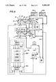
- FIG. 1 is a diagram of an apparatus for freezing and dispensing semi-frozen food products and a control system therefor according to a first embodiment of this invention
- FIG. 2 is a flow chart of a program for operating the control system of FIG. 1;
- FIGS. 3a, 3b and 3c are graphs illustrating the pulse width modulated signals applied to the solenoid valves associated with both freezing chambers, under different operating modes;
- FIG. 4 is a flow chart of a modified program for operating the control system of FIG. 1;
- FIG. 5 is a diagram of a refrigerating system according to a further embodiment of this invention.
- FIG. 6 is a flow chart of a program for operating the control system of FIG. 5.
- FIG. 1 illustrates an apparatus for freezing and dispensing semi-frozen food products having two freezing chambers C1 and C2 for dispensing food products of different flavors or types.
- the freezing chambers are commonly in the form of an elongated cylinder and respectively have beaters B1 and B2 mounted for axial rotation in the cylinders.
- Product to be frozen is supplied to the cylinders C1 and C2 from product supplies PS1 and PS2, and evaporators E1 and E2 extend around the freezing chambers C1 and C2 for refrigerating the product therein.
- the product supplies are generally arranged to supply a liquid comestible and an edible gas in proportions to provide a semi-frozen food product having the desired overrun.
- the liquid comestible may, for example, be of the type used to make soft ice cream, sherbert, shakes or ice slushes, and the gas can be air, nitrogen, carbon dioxide or a mixture thereof.
- the product supplies may also be refrigerated by suitable apparatus (not shown) to pre-cool the liquid therein to preselected above freezing temperatures.
- Selectively operable dispensing valve means are provided for controlling dispensing of semi-frozen product from the freezing chambers, preferably at the end of the cylinders remote from the product supply inlet.
- valves V1 and V2 are provided in heads 11 at a discharge end of the cylinder for respectively dispensing semi-frozen product from chambers C1 and C2.
- a third dispensing valve (not shown) which is arranged to dispense product from both freezing chambers simultaneously, when a mixture of the products from the two freezing chambers is desired.
- Means are provided for producing a signal when product is dispensed from either freezing chamber.
- This means may comprise switches S1 and S2 arranged to sense when a dispensing valve is open to dispense product from freezing chambers C1 and C2 respectively.
- the dispense sensing means can also be arranged to sense other conditions that change when product is dispensed from a freezing chamber, such as the infeed of product from the associated product supply as occurs when the dispensing valve is opened, or the change in vicosity of the product in the freezing chamber as occurs when the dispensing valve is opened.
- the switches are positioned so as to be actuated when the associated dispensing valve is opened or raised to dispense a product.
- Some apparatus have a third valve for dispensing product simultaneously from both freezing chambers, and in such apparatus the third dispensing valve is arranged in a manner well known in the art to operate both switches S1 and S2 simultaneously when the third valve is opened to dispense product from both freezing chambers.
- a single beater drive motor BM is provided for driving both beaters B1 and B2. As shown, drive motor BM is connected to an input shaft 15 of a power transmission 16 having dual output shafts 17 and 18 respectively connected to the beaters B1 and B2. The beater drive motor, when energized, drives both beaters concurrently.
- Refrigerant is supplied to the evaporators E1 and E2 for both freezing chambers from a single compressor CP driven by a compressor motor CM.
- the compressor CP has high pressure outlet line 21 connected to a condenser 22 and the outlet of the condenser is connected through a high pressure refrigerant supply line 23 to on/off type solenoid valves SV1 and SV2 respectively arranged to control the supply of refrigerant to evaporators E1 and E2.
- Evaporators E1 and E2 are otherwise connected through a low pressure refrigerant return line 25 and an accumulator 26 to the suction side 27 of the compressor.
- the solenoid valves SV1 and SV2 are of the type which can be rapidly cycled between an open position passing flow of refrigerant to an associated evaporator and a closed position blocking flow of refrigerant and the solenoid valves are pulse width modulated in a manner described more fully hereinafter to control refrigeration of the associated freezing chamber.
- Product condition sensing means are provided for sensing a condition of the product in the freezing chambers that is related to a minimum servable product viscosity.
- the product condition sensing means includes a load sensing means 31 for sensing the combined drive load for driving both the beaters B1 and B2 concurrently, and a temperature sensing means T1 and T2 respectively arranged to sense the product temperature in the freezing chambers C1 and C2.
- Temperature sensors can sense the temperature of the product only in a localized area of the freezing chambers and the temperature sensors are preferably arranged to sense the product temperature adjacent the outlet or discharge end of the freezing chambers.
- the temperature sensors may, for example, comprise thermistors mounted in the discharge heads 11 and which extend into a cavity in the head that communicates with the product in the freezer chamber.
- a control means 32 is provided for controlling operation of compressor drive motor beater drive motor and the solenoid valves.
- the control means 32 includes an input circuit 32a, a programmable controller 32b and an output circuit 32c.
- the input circuit 32a is electrically connected to the dispense switching switches S1 and S2 and is also connected to the temperature sensers T1 and T2 to receive signals therefrom.
- the input circuit is also connected to the load sensor 31 that senses the combined load on the beater motor for driving both beaters B1 and B2 concurrently.
- the programmable controller 32b is connected between the input circuit 32a and the output circuit 32b and executes preset signal processing and/or calculations with respect to signals fed from the input circuit 32a and thereby generates secondary signals fed to the output circuit 32c.
- the output circuit generates control signals in accordance with the secondary signals and the output circuit is electrically connected to the solenoid valves SV1 and SV2; to a compressor contactor 35 for the compressor motor, and to a beater contactor 36 for the beater motor.
- the solenoid valves SV1 and SV2 and the compressor motor and beater motor are controlled by way of signals applied to the these devices from the output circuit 32c.
- the programmable controller 32b includes a central processing unit (CPU) read only memory (ROM), a random access memory (RAM), and a clock generator (Clock).
- the clock generator is connected to the CPU, the ROM and the RAM and, during signal processing, the CPU electronically scans a control program stored in memory and reads the status of the inputs and executes commands to the appropriate output based on input conditions and what they mean to the stored program.
- the CPU also performs other functions such as math operations, timing, and counting.
- the programmable controller 32b may, for example, comprise a microcontroller such as marketed by Intel Corporation, Santa Clara, Calif. No. 8098.
- the 8098 microcontroller has an on-chip A/D converter for converting analog signals to digital signals and a plurality of on-chip pulse width modulated outputs.
- Other microprocessors or micro- controllers can be used and discrete A/D converters and/or pulse width modulators provided, if required.
- the dispense sensing switches S1 and S2 are preferably on/off type switches which provide a digital signal to the input circuit when its associated dispense valve is open.
- the temperature sensors are of a type such as a thermistor which provides an analog signal correlative with the temperature of the product sensed by the temperature sensor and these temperature sensors apply an analog signal to the input circuit.
- the beater load sensing means 31 can be of various known types and may, for example, comprise a torque sensitive coupling in the shaft 15 that produces a digital signal when the drive torque reaches a value correlative with a desired servable product viscosity. In the embodiment of FIG.
- the load sensor 31 is preferably of a type that senses a current or voltage condition in the beater drive motor, which is correlative with the combined drive load for driving both beaters.
- the solenoid valves SV1 and SV2 are adapted to rapidly move between closed and open positions and back, and the period of the pulse width modulated signals and the duty cycles of the signals applied to the valves SV1 and SV2 is selected so that the valves move between a fully closed and fully opened position and back during each period.
- the programmable controller 32 is arranged to apply pulse width modulated signals to the solenoid valves SV1 and SV2 alternately during each period, and the sum of the duty cycles of the pulse width modulated signals applied during each period is made less than 100% of the period, to provide time between the duty cycles of the two valves sufficient to allow one valve to close before the other valve opens. Since each valve closes before the other opens, opening of the valve associated with one evaporator does not affect the flow of refrigerant to the other evaporator.
- the total time that the solenoid valves are open during each period affects the head and suction pressures on the compressor and hence the temperature to which the product can be frozen in the freezing chambers.
- the combined duration of the pulse width modulated signals applied to both solenoid valves during each period is made adjustable in a range from about 60% to 90% of the period of the pulse width modulated signals to operate the refrigeration system at a preselected percent of its full capacity product freeze rate at which the system will freeze the product in the freezing chambers to the desired servable product viscosity.
- increasing the combined duty cycles toward the upper end of the range effects freezing of the product to a lower temperature and provides a higher product viscosity.
- the duty cycles of pulse width modulated signals for the solenoid valves SV1 and SV2 are changed in different operating modes.
- the sum of the duty cycles of the pulse width modulated signals applied to the valves SV1 and SV2 during each period is preferably substantially the same in each of the different operating modes.
- the proper percent of full capacity product freeze rate can be readily determined by first operating the apparatus in an initial freeze mode with the duty cycles PWF1 preset at a preselected percent of full capacity product freeze rate and the duty cycles PWF1 then increased or decreased as required to freeze the product to the desired minimum servable product viscosity for that product.
- the solenoid valves are operated alternately during each period of the pulse width modulated signals and the sum of the duty cycles of pulse width modulated signals PWF1 accordingly equals X percent of the period or X percent of the full capacity product freeze rate.
- the apparatus is preferably operated in all of its modes at the same X percent of the full capacity product freeze rate for the product.
- PFW1 is preset so that 2 times PWF1 substantially equal X percent of the full capacity product freeze rate
- PWH plus PWF2 are preferably preset to substantially equal the same X percent of the full capacity product freeze rate.
- PWH is the duty cycle required to produce an effective refrigeration flow rate sufficient to compensate for heating of the product in the freezing chamber due to rotation on the beater therein.
- the duty cycle PWH is low as compared to PWF1, and can be empirically determined, for example by continuosly operating the beater in a freezing cylinder filled with the product to the dispensed and adjusting the duty cycle until the product is maintained at the desired viscosity. It has been found that for many products, PWH is in the order of nine to twelve percent of the full capacity product freeze rate of the apparatus.
- the solenoid valve associated with one freezing chamber is modulated at a duty cycle PWH
- the solenoid valve associated with the other freezing chamber is preferably modulated at a duty cycle PWF2 substantially equal to X percent of the full capacity freeze rate minus PWH, so that the sum of the duty cycles PWH and PWF2 substantially equal X percent of the full capacity product freeze rate.
- the control circuit 32 operates in accordance with a program stored in the RAM within the programmable control 32b.
- the freezing chamber C1 evaporator E1, dispense valve V1 and solenoid valve SV1 are collectively referred to as side 1 and the freezing chamber C2, evaporator E2 dispense valve V2 and solenoid valve SV2 are collectively referred to as side 2.
- FIG. 2 is a flow chart of a program for operating the apparatus of FIG. 1. An "auto" cycle is started as by closing of a switch, (not shown) for example at the beginning of the day of operation of the freezing and dispensing apparatus.
- An "auto" cycle can also be started by a timer (not shown) at preselected times during the day or at a preselected time interval, for example a preset number of minutes, after the last preceeding dispensing operation.
- a first step 201 of the program initializes parameters and sets a reference combined beater load CBL and reference duty cycles PWF1, PWF2 and PWH.
- the control means determines if it is an initial freeze cycle and, if it is, the control sets an initial freeze flag as indicated in step 203 and in step 204 proceeds to generate and apply periodic pulse width modulated signals having substantially equal duty cycles PWF1 to the solenoid valves SV1 and SV2 associated with both freezing chambers.
- the pulse width modulated signals are preferably applied to the solenoid valves associated with the two freezing chambers alternately during each period, and the duty cycles PWF1 are each less than 50% of the period as graphically illustrated in FIG. 3a. Operation of the apparatus in this initial freeze mode continues until the program in step 205 determines that the combined beater load outputted from load sensor 31 reaches the preset reference value CBL stored in the memory of the programmable controller. Since the duty cycles of the pulse width modulated signals applied to both solenoids is the same during the initial freezing cycle, the product in both freezing chambers will be balanced, that is have substantially the same viscosity and temperature when the combined beater load reaches the reference CBL at the completion of one initial freeze cycle.
- the program determines in step 206 if one initial freeze flag has been set and, if it has, the program operates the in step 207 to derive the current value of the product temperatures from the signals outputed by temperature sensors T1 and T2 and to calculate and store minimum servable product reference temperatures MSPT1 and MSPT2 respectively correlative with the current value of the product temperatures outputed by sensors T1 and T2, and the program proceeds in step 208, to set flags for reference temperatures MSPT1 and MSPT2.
- the reference temperatures compensate for any differences in the signal outputed from the two temperature sensors at the same product temperature. Further if the reference combined beater load CBL is changed to a new reference CBL, the program automatically adjusts the reference temperatures MSPT1 and MSPT2 to the temperature signals outputed from the sensors T1 and T2 at the new reference CBL.
- the reference temperatures MSPT1 and MSPT2 are subsequently used to determine if the current product temperature in the respective cylinders C1 and C2 are at or below a minimum servable product viscosity, and MSPT1 and MSPT2 are preferably calculated and set so as to be slightly lower, for example about one degree, lower than the current value of the product temperatures derived from the signal outputed by the temperature sensors T1 and T2 at the time the combined beater load reaches the reference combined beater load CBL.
- step 211 the control compares the current value of the temperatures outputed from temperature sensors T1 and T2 with the reference temperatures MSPT1 and MSPT2, and, if the current temperatures are at or below the respective reference temperatures, the control operates in step 212 to turn off the beater motor and compressor motor. If the current product temperatures in both freezing chambers are not at or below the respective reference temperatures, the control continues operation of the compressor and beater motor and in step 213 compares the current temperature signal outputed from sensor T1 with the reference temperature MSPT1.
- the control operates in step 214 to modulate the signals supplied to solenoid valve SV1 at a duty cycle PWH and modulate the signals supplied to solenoid valve SV2 at a duty cycle PWF2 as graphically illustrated in FIG. 3b.
- the duty cycle PWH is selected to provide an effective refrigerant flow rate to the evaporator associated with freezing chamber C1 which is sufficient to substantially maintain the viscosity of the product in freezing chamber C1 while the beater is rotating therein.
- the duty cycle PWF2 provides an effective refrigerant flow rate substantially greater than PWH and sufficient to increase the viscosity of the product in the other freezing chamber C2.
- step 215 determines that the product temperature in freezing chamber C2 is below the reference temperature MSPT2 for that chamber.
- the control operates in step 216 to modulate the signal applied to solenoid valve SV1 at a duty cycle PWF2 and to modulate the solenoid valve SV2 associated with the freezing chamber C2 at a duty cycle PWH as graphically illustrated in FIG. 3c, until the control in step 217 determines that the current product temperature outputed by the signal from the sensor T2, is below the reference temperature MSPT1.
- Product can be intermittently dispensed from either freezing chamber and the duration of each dispensing operation and the intervals between dispensing operations from the two chambers varies widely.
- the control system is operative in response to signals outputed by the dispense switches S1 and S2, to turn on the compressor and beater motor, and to modulate the signals applied to the solenoid valves while one or the other draw switch or both draw valves are open.
- the control determines if only draw switch S1 is open and, if it is, the control in step 222 modulates the signal applied to valve SV1 at a duty cycle PWF2 and modulates the signal applied to valve SV2 associated with the other freezing chamber at a duty cycle PWH.
- step 223 the control determines if the draw is from only the second freezing chamber and, if it is, it proceeds in step 224 to modulate the signals applied to solenoid valve SV2 at a duty cycle PWF2 and modulate the signal applied to the solenoid valve SV1 at a duty cycle PWH. If the draw is not from side one only or side 2 only, the control in step 223 determines that the draw is from both the freezing chambers and in step 225 operates to modulate the solenoid valves SV1 and SV2 at the same duty cycles PWF1 to refrigerate both freezing chambers at substantially the same rate.
- Step 225 is also executed when an "auto" cycle is initiated by a timer at preselected times during the day or at a preselected time interval after the last dispensing operation.
- the control system is operative to continue operation of the compressor and beater motor and to modulate the control signals in accordance with steps 222, 224 or 225 dependent on whether the last draw signal indicated that product was dispensed from side 1, side 2, or both sides, until the control determines in step 205 that the combined beater load derived from load sensor 31 exceeds the reference combined beater load CBL.
- the control system continues operation of the compressor and beater motor and proceeds in step 211 to compare the current value of the product temperatures from sensors T1 and T2 to the minimum servable product reference temperatures MSPT1 and MSPT2. If the temperature outputed from sensors T1 and T2 are at or below the respective reference temperature system in step 212 turns off the beater motor and compressor motor. If temperatures outputed from sensors T1 and T2 are not at or below the respective reference temperatures, the control system continues operation of the compressor and beaters and modulates signals applied to the solenoid valves SV1 and SV2 in the manner previously described in connection with steps 213-217 and in step 218 turns off the compressor and beater motors.
- FIG. 4 illustrates a modified flow chart for operating the apparatus of FIG. 1.
- the first step 201' initializes parameters and sets a reference combined meter load CBL; and pulse width duty cycles PWH, PWF1 and PWF2, and a reference minimum servable product temperature MSPT.
- the flow diagram in FIG. 4 is similar to that in FIG.
- step 202' determines whether it is an initial freeze cycle. If it is the initial freeze cycle, the control system operates in step 204' to modulate the solenoid valves SV1 and SV2 at substantial equal duty cycles PWF1, and operation in this initial freeze mode continues until the program in step 205" determines than the current value of the combined beater load outputed sensor 31 reaches the reference combined beater load CBL.
- step 211' the control determines whether the product temperatures currently outputed from temperature sensors T1 and T2 are at or lower than the minimum servable product reference temperatures MSPT and, if yes, operates in step 212' to turn off the beater motor and compressor motor. If the current temperature signals outputed by sensors T1 and T2 are not both equal to the minimum servable product reference temperature MSPT, the control operates in steps 213'-218' in the manner previously described in connection with steps 213-218 in FIG. 2. When product is dispensed from one freezing chamber or the other freezing chamber or both freezing chambers, the control system operates in steps 221'-225' in the manner previously described in connection with steps 221-225 in FIG. 2. Thus, the flow chart of FIG. 4 differs from that in FIG. 2 primarily in presetting the minimum servable product reference temperature MSPT rather than calculating individual reference minimum servable product temperatures for freezing chambers C1 and C2.
- the apparatus for freezing and dispensing semi-frozen food products and the control system therefor illustrated in FIG. 5 is generally the same as that illustrated in FIG. 1 and like numerals are used to designate the same parts and like numerals followed by the postscript " are used to designate modified parts.
- the apparatus of FIG. 5 differs from that i FIG. 1 essentially in that it uses two beater load sensors 31a" and 31b" in lieu of the combined beater load sensor 31 and temperature sensors T1 and T2 in FIG. 1.
- FIG. 6 is a flow chart of a program for operating the apparatus in FIG. 5.
- An “auto" cycle is started by closing of a switch (not shown) for example at the beginning of the day of operation of the freezing and dispensing apparatus.
- a “auto” cycle can also be started by a timer (not shown) at preselected times during the day or at a preselected time interval for example a preset number of minutes after the last preceeding dispensing operation.
- the first step 201" of the program initalizes parameters and sets reference beater loads BL1 and BL2, and duty cycles PWH, PWF1 and PWF2.
- the control means determines if it is an initial freeze cycle and, if it is, the control in step 204" generates and applies periodic pulse width modulated signals having substantially the same duty cycle PWF1 to the solenoid valves SV1 and SV2 associated with both freezing chambers.
- the pulse width modulated signals are preferably applied to the solenoid valves associated with the two freezing chambers alternately during each period and the duty cycles PWF1 are each less than 50% of the period.
- step 205" determines that either the beater load sensed by sensor 31a” or the beater load sensed by sensor 31b" exceeds the respective reference beater load BL1 or BL2.
- the program in step 211" determines if the beater load for driving beater B1 in freezing chamber C1 is at or above the reference beater load BL1.
- step 214" If the load on the beater B1 is not at or above the reference beater load BL1, the control continues operation of the compressor and in step 214" generates and applies pulse width modulated signals having a duty cycle PWF2 to the solenoid valve associated with chamber C1 and pulse width modulated signals having a duty cycle PWH to the solenoid valve SV2 associated with cylinder C2.
- the program continues to operate the apparatus in this mode until the control in step 215" determines that the beater load outputed from sensor 31a" exceeds the reference beater load BL1, and the control then turns off the beater motor and compressor motor as indicated in step 218".
- step 211 determines in step 211" that the drive load outputed from load sensor 31a" is at or above the reference drive load BL1
- the program proceeds to step 212" and determines if the load outputed from sensor 31b" is at or above reference beater load BL2 and, if yes, the control in step 213" shuts off the beater motor and compressor motor.
- step 216 If the load outputed by load censor 31b" is not at or above the reference beater load BL2, the program operates in step 216" to generate and apply a pulse width modulated signal having a duty cycle PWF2 to the solenoid valve SV2 associated with freezing chamber C2, and to generate and apply a pulse width modulated signals having a duty cycle PWH to the solenoid valve SV1 associated with the freezing chamber C1.
- the control in step 217" continues operation in this mode until the beater load output from sensor 31b" exceeds the reference beater load BL2 and the control then operates in step 220" to turn off the beater motor and compressor.
- product can be intermittently dispensed from either freezing chamber and the duration of each dispensing operation and intervals between the dispensing operation from the two chambers varies widely.
- the control system in FIG. 6 is operative in response to signals outputed by the dispense switches S1 and S2, to turn on the compressor and beater motors, and to modulate the signals applied to the solenoid valves S1 and S2 while one or the other of the draw valves are open.
- step 221 the control determines if only draw switch SV1 is open and, if it is, the control in step 222" generates and applies a pulse width modulated signal to valve SV1 having a duty cycle PWF2 and generates and applies a pulse width modulated signal having a duty cycle PWH to the solenoid valve associated with freezing chamber C1. If the draw switch S1 is not actuated, then the control determines in step 223" if only the draw switch S2 is actuated.
- the control in step 224", generates and applies a pulse switch modulated signal having a duty cycle PWF2 to the solenoid valve SV2 and generates and applies a pulse width modulated signal having a duty cycle PWH to the solenoid valve SV1. If, in steps 221" and 223", the control determines that the draw is not from only freezing chamber C1 or from only freezing chamber C2, then it follows that the draw is from both freezing chambers C1 anc C2 or that the "auto" cycle has been initiated by the timer. Under these conditions, the control operates in step 225" to generate and apply pulse width modulated signals having substantial equal duty cycles PWF1 to the solenoid valves associated with both freezing chambers.
- the control continues operation of the compressor and applies pulse with modulated signals to the solenoid valves SV1 and/or SV2 in accordance with steps 222", 224" or 225" until the control in step 205" determines that the beater load sensed either of the load sensors 31a" or 31b' exceeds the respective reference beater load BL1 or BL2.
- the control thereafter continues operation in the manner previously described in connection with steps 211"-220" until the beater loads outputed from sensors 31a and 31b reach the reference beater loads BL1 and BL2.
- both the compressor motor and beater motors are turned off in steps 213", 218", and 220".
- the beater motor can be operated in continuous fashion to maintain the ice particles in suspension.
Landscapes
- Engineering & Computer Science (AREA)
- Life Sciences & Earth Sciences (AREA)
- Food Science & Technology (AREA)
- Chemical & Material Sciences (AREA)
- Physics & Mathematics (AREA)
- Polymers & Plastics (AREA)
- General Physics & Mathematics (AREA)
- Mechanical Engineering (AREA)
- Thermal Sciences (AREA)
- General Engineering & Computer Science (AREA)
- Manufacturing & Machinery (AREA)
- Remote Sensing (AREA)
- Automation & Control Theory (AREA)
- Confectionery (AREA)
Abstract
Description
Claims (25)
Priority Applications (1)
| Application Number | Priority Date | Filing Date | Title |
|---|---|---|---|
| US07/875,836 US5205129A (en) | 1992-04-30 | 1992-04-30 | Apparatus for freezing and dispensing semi-frozen food products having dual freezing chambers and method |
Applications Claiming Priority (1)
| Application Number | Priority Date | Filing Date | Title |
|---|---|---|---|
| US07/875,836 US5205129A (en) | 1992-04-30 | 1992-04-30 | Apparatus for freezing and dispensing semi-frozen food products having dual freezing chambers and method |
Publications (1)
| Publication Number | Publication Date |
|---|---|
| US5205129A true US5205129A (en) | 1993-04-27 |
Family
ID=25366442
Family Applications (1)
| Application Number | Title | Priority Date | Filing Date |
|---|---|---|---|
| US07/875,836 Expired - Lifetime US5205129A (en) | 1992-04-30 | 1992-04-30 | Apparatus for freezing and dispensing semi-frozen food products having dual freezing chambers and method |
Country Status (1)
| Country | Link |
|---|---|
| US (1) | US5205129A (en) |
Cited By (47)
| Publication number | Priority date | Publication date | Assignee | Title |
|---|---|---|---|---|
| US5617734A (en) * | 1995-03-27 | 1997-04-08 | Island Delite, Ltd. | Low temperature composition preparation device, and methods of constructing and utilizing same |
| WO1997026801A1 (en) * | 1996-01-23 | 1997-07-31 | Frank Jimmy I | Apparatus and method for controlling the flow rate of refrigerant to a refrigeration device |
| US5713209A (en) * | 1996-10-24 | 1998-02-03 | General Mills, Inc. | Twin screw extruder for batch freezing |
| US5778767A (en) * | 1997-03-14 | 1998-07-14 | Base Design, Inc. | Dispenser apparatus |
| US5868065A (en) * | 1996-09-16 | 1999-02-09 | Kateman Family Limited Partnership | Apparatus for manufacturing frozen confection |
| USRE36390E (en) * | 1993-01-28 | 1999-11-16 | Fels Ulrich | Device for cooling of fluids and edible foams |
| US6079215A (en) * | 1998-01-06 | 2000-06-27 | Integrated Biosystems, Inc. | Method for freeze granulation |
| US6109051A (en) * | 1998-05-15 | 2000-08-29 | Manitowoc Foodservice Group, Inc. | Food preparation table with air blast chiller |
| US6170269B1 (en) | 1998-01-06 | 2001-01-09 | Integrated Biosystems, Inc. | System for freeze granulation |
| US6176090B1 (en) | 1999-08-17 | 2001-01-23 | Rich Coast Corporation | Frozen cappuccino and fruit smoothie macerator |
| US6207213B1 (en) * | 1996-05-21 | 2001-03-27 | Nestac S.A. | Frozen concentrated milk and preparation thereof |
| DE10011904A1 (en) * | 2000-03-11 | 2001-09-13 | Lumen Gmbh | Device for monitoring and controlling devices for the production of ice cream, milkshakes or the like |
| US6619056B2 (en) * | 1997-04-18 | 2003-09-16 | Bunn-O-Matic Corporation | Cold drink system |
| US20030211192A1 (en) * | 1999-05-28 | 2003-11-13 | Good Humor - Breyers Ice Cream, Division Of Conopco, Inc. | Process and apparatus for production of a frozen food product |
| US20040060306A1 (en) * | 2002-09-30 | 2004-04-01 | Kan-Pak, L.L.C. | Semi-frozen beverage dispensing apparatus |
| WO2004038309A1 (en) * | 2002-10-23 | 2004-05-06 | Carrier Commercial Refrigeration, Inc. | Refrigeration system to cool a mix |
| US20040226305A1 (en) * | 2003-05-16 | 2004-11-18 | Spm Drink Systems S.R.L. | Machine for dispensing icy beverages |
| US6858424B2 (en) | 1998-01-06 | 2005-02-22 | Integrated Biosystems, Inc. | Cryopreservation vial apparatus and methods |
| EP1588981A1 (en) * | 2004-03-31 | 2005-10-26 | Gerhard Holzapfel | Process for making fresh ice creams and dispenser using this process |
| US20060007623A1 (en) * | 2004-07-09 | 2006-01-12 | Trivette Marty L | Method and apparatus for operating a magnetic actuator in a power switching device |
| EP1713038A1 (en) * | 2005-04-13 | 2006-10-18 | Delphi Technologies, Inc. | High efficiency beverage vending machine |
| GB2427673A (en) * | 2005-06-27 | 2007-01-03 | Imi Cornelius | Method and apparatus for producing a frozen beverage |
| US20080041876A1 (en) * | 2006-08-18 | 2008-02-21 | Frank Jimmy I | Multi-ingredient food dispensing machine |
| WO2008128023A1 (en) * | 2007-04-11 | 2008-10-23 | Tiax Llc | Food dispensers and related methods |
| US20080289357A1 (en) * | 2007-05-22 | 2008-11-27 | Skobel Robert M | Liquid nitrogen cooled beverage dispenser |
| US20090000315A1 (en) * | 2007-04-24 | 2009-01-01 | Imi Cornelius Inc. | Defrost control for multiple barrel frozen product dispensers |
| ITRM20080599A1 (en) * | 2008-11-07 | 2010-05-07 | Elmeco Srl | DEVICE FOR THE PRODUCTION OF "SOFT" ICE CREAM OR SIMILAR PRODUCTS, WITH PORTIONER AND DOSE COUNTER. |
| ITBO20090416A1 (en) * | 2009-06-29 | 2010-12-30 | Carpigiani Group Ali Spa | Slush. |
| WO2010098851A3 (en) * | 2009-02-25 | 2011-10-20 | Moobella, Inc. | System and method of temperature adjustment and control of food processing/dispensing system or apparatus |
| US20120223094A1 (en) * | 2011-03-03 | 2012-09-06 | Soft Serve Parts Llc | Intelligent monitoring and control system for dispensed chilled food product devices |
| US20120312049A1 (en) * | 2011-03-03 | 2012-12-13 | Soft Serve Parts Llc | Intelligent monitoring and control system for dispensed chilled food product devices |
| US20130074527A1 (en) * | 2010-06-24 | 2013-03-28 | Woongjin Coway Co., Ltd | Ice making method |
| US20150289539A1 (en) * | 2012-10-30 | 2015-10-15 | Nestec S.A. | Beverage machine for preparing and dispensing iced beverages |
| EP3042570A1 (en) * | 2015-01-09 | 2016-07-13 | ALI S.p.A. - CARPIGIANI GROUP | Machine and method for making two liquid or semi-liquid food products |
| US20160229675A1 (en) * | 2015-02-09 | 2016-08-11 | Fbd Partnership, Lp | Multi-flavor food and/or beverage dispenser |
| US20180084800A1 (en) * | 2015-04-27 | 2018-03-29 | Nestec S.A. | Machine for preparing a cooled or heated product with accurate temperature control |
| WO2019036275A1 (en) | 2017-08-18 | 2019-02-21 | Taylor Commercial Foodservice Inc. | Heat exchanger and method of making thereof |
| WO2022017631A1 (en) * | 2020-07-23 | 2022-01-27 | Kempische Brik Centrale | A device for preparing a frozen food product from a liquid mixture |
| US11477992B2 (en) | 2020-07-23 | 2022-10-25 | Immo Dalo Nv | Device for preparing a frozen food product from a liquid mixture |
| EP3921273A4 (en) * | 2019-02-06 | 2022-11-09 | The Coca-Cola Company | FROZEN BEVERAGE DISPENSER CONTROL |
| US12279629B1 (en) | 2024-01-18 | 2025-04-22 | Sharkninja Operating Llc | Mixing vessel baffles for a drink maker |
| USD1076580S1 (en) | 2024-01-18 | 2025-05-27 | Sharkninja Operating Llc | Drink maker dasher |
| USD1091236S1 (en) | 2024-01-18 | 2025-09-02 | Sharkninja Operating Llc | Collection tray for a drink maker |
| US12414578B1 (en) | 2025-03-14 | 2025-09-16 | Sharkninja Operating Llc | Shared output connector assembly for two drink maker dispenser assemblies |
| US12446594B2 (en) | 2024-01-18 | 2025-10-21 | Sharkninja Operating Llc | Drink maker with detachably connectable mixing vessel |
| US12514262B1 (en) | 2025-01-10 | 2026-01-06 | Sharkninja Operating Llc | Feature for preventing material buildup in a mixing vessel of a drink maker |
| US12520857B1 (en) | 2025-01-09 | 2026-01-13 | Sharkninja Operating Llc | Multi-stage dispenser assembly |
Citations (6)
| Publication number | Priority date | Publication date | Assignee | Title |
|---|---|---|---|---|
| US1442945A (en) * | 1921-12-14 | 1923-01-23 | Hauk Edwin | Method for producing ice cream |
| US2608833A (en) * | 1949-07-29 | 1952-09-02 | Ben H Woodruff | Frozen custard machine |
| US3626709A (en) * | 1969-11-24 | 1971-12-14 | Astro Control Inc | Apparatus for preparation of frozen confections |
| US4869072A (en) * | 1988-05-09 | 1989-09-26 | Icee-Usa Corporation | Partially frozen beverage dispensing system having a counter top unit |
| US5095710A (en) * | 1990-03-19 | 1992-03-17 | Imi Cornelius Inc. | Frozen carbonated beverage apparatus and method and control system therefor |
| US5158506A (en) * | 1989-12-19 | 1992-10-27 | Sanyo Electric Co., Ltd. | Ice-cream manufacturing apparatus and refrigeration controller therefor |
-
1992
- 1992-04-30 US US07/875,836 patent/US5205129A/en not_active Expired - Lifetime
Patent Citations (6)
| Publication number | Priority date | Publication date | Assignee | Title |
|---|---|---|---|---|
| US1442945A (en) * | 1921-12-14 | 1923-01-23 | Hauk Edwin | Method for producing ice cream |
| US2608833A (en) * | 1949-07-29 | 1952-09-02 | Ben H Woodruff | Frozen custard machine |
| US3626709A (en) * | 1969-11-24 | 1971-12-14 | Astro Control Inc | Apparatus for preparation of frozen confections |
| US4869072A (en) * | 1988-05-09 | 1989-09-26 | Icee-Usa Corporation | Partially frozen beverage dispensing system having a counter top unit |
| US5158506A (en) * | 1989-12-19 | 1992-10-27 | Sanyo Electric Co., Ltd. | Ice-cream manufacturing apparatus and refrigeration controller therefor |
| US5095710A (en) * | 1990-03-19 | 1992-03-17 | Imi Cornelius Inc. | Frozen carbonated beverage apparatus and method and control system therefor |
Cited By (74)
| Publication number | Priority date | Publication date | Assignee | Title |
|---|---|---|---|---|
| USRE36390E (en) * | 1993-01-28 | 1999-11-16 | Fels Ulrich | Device for cooling of fluids and edible foams |
| US5617734A (en) * | 1995-03-27 | 1997-04-08 | Island Delite, Ltd. | Low temperature composition preparation device, and methods of constructing and utilizing same |
| US5743097A (en) * | 1996-01-23 | 1998-04-28 | Frank; Jimmy I. | Apparatus and method for controlling the flow rate of refrigerant to a refrigeration device |
| WO1997026801A1 (en) * | 1996-01-23 | 1997-07-31 | Frank Jimmy I | Apparatus and method for controlling the flow rate of refrigerant to a refrigeration device |
| US6207213B1 (en) * | 1996-05-21 | 2001-03-27 | Nestac S.A. | Frozen concentrated milk and preparation thereof |
| US5868065A (en) * | 1996-09-16 | 1999-02-09 | Kateman Family Limited Partnership | Apparatus for manufacturing frozen confection |
| US5713209A (en) * | 1996-10-24 | 1998-02-03 | General Mills, Inc. | Twin screw extruder for batch freezing |
| US5778767A (en) * | 1997-03-14 | 1998-07-14 | Base Design, Inc. | Dispenser apparatus |
| US6619056B2 (en) * | 1997-04-18 | 2003-09-16 | Bunn-O-Matic Corporation | Cold drink system |
| US6079215A (en) * | 1998-01-06 | 2000-06-27 | Integrated Biosystems, Inc. | Method for freeze granulation |
| US6170269B1 (en) | 1998-01-06 | 2001-01-09 | Integrated Biosystems, Inc. | System for freeze granulation |
| US6858424B2 (en) | 1998-01-06 | 2005-02-22 | Integrated Biosystems, Inc. | Cryopreservation vial apparatus and methods |
| US6109051A (en) * | 1998-05-15 | 2000-08-29 | Manitowoc Foodservice Group, Inc. | Food preparation table with air blast chiller |
| US20030211192A1 (en) * | 1999-05-28 | 2003-11-13 | Good Humor - Breyers Ice Cream, Division Of Conopco, Inc. | Process and apparatus for production of a frozen food product |
| US6176090B1 (en) | 1999-08-17 | 2001-01-23 | Rich Coast Corporation | Frozen cappuccino and fruit smoothie macerator |
| DE10011904A1 (en) * | 2000-03-11 | 2001-09-13 | Lumen Gmbh | Device for monitoring and controlling devices for the production of ice cream, milkshakes or the like |
| EP1132007A3 (en) * | 2000-03-11 | 2003-09-03 | LUMEN GmbH Nährmittel- und Maschinenfabrik | Device for controlling and monitoring apparatus for the production of ice-cream, milkshake and the like |
| US20040060306A1 (en) * | 2002-09-30 | 2004-04-01 | Kan-Pak, L.L.C. | Semi-frozen beverage dispensing apparatus |
| US6766650B2 (en) * | 2002-09-30 | 2004-07-27 | Kan-Pak, L.L.C. | Semi-frozen beverage dispensing apparatus |
| AU2003277412B2 (en) * | 2002-10-23 | 2009-04-02 | Carrier Commercial Refrigeration, Inc. | Refrigeration system to cool a mix |
| WO2004038309A1 (en) * | 2002-10-23 | 2004-05-06 | Carrier Commercial Refrigeration, Inc. | Refrigeration system to cool a mix |
| CN100529586C (en) * | 2002-10-23 | 2009-08-19 | 开利商业冷藏公司 | Refrigeration system for cooling a mixture |
| US20040226305A1 (en) * | 2003-05-16 | 2004-11-18 | Spm Drink Systems S.R.L. | Machine for dispensing icy beverages |
| EP1588981A1 (en) * | 2004-03-31 | 2005-10-26 | Gerhard Holzapfel | Process for making fresh ice creams and dispenser using this process |
| US20060007623A1 (en) * | 2004-07-09 | 2006-01-12 | Trivette Marty L | Method and apparatus for operating a magnetic actuator in a power switching device |
| US7508645B2 (en) * | 2004-07-09 | 2009-03-24 | Abb Technology Ag | Method and apparatus for operating a magnetic actuator in a power switching device |
| EP1713038A1 (en) * | 2005-04-13 | 2006-10-18 | Delphi Technologies, Inc. | High efficiency beverage vending machine |
| US7228989B2 (en) | 2005-04-13 | 2007-06-12 | Delphi Technologies, Inc. | High efficiency beverage vending machine |
| US20060231565A1 (en) * | 2005-04-13 | 2006-10-19 | Bhatti Mohinder S | High efficiency beverage vending machine |
| GB2427673A (en) * | 2005-06-27 | 2007-01-03 | Imi Cornelius | Method and apparatus for producing a frozen beverage |
| GB2427673B (en) * | 2005-06-27 | 2010-02-10 | Imi Cornelius | Frozen beverages |
| US20080041876A1 (en) * | 2006-08-18 | 2008-02-21 | Frank Jimmy I | Multi-ingredient food dispensing machine |
| WO2008128023A1 (en) * | 2007-04-11 | 2008-10-23 | Tiax Llc | Food dispensers and related methods |
| US20090000315A1 (en) * | 2007-04-24 | 2009-01-01 | Imi Cornelius Inc. | Defrost control for multiple barrel frozen product dispensers |
| US20140208786A1 (en) * | 2007-04-24 | 2014-07-31 | Imi Cornelius, Inc. | Defrost Control For Multiple Barrel Frozen Product Dispensers |
| US9328948B2 (en) * | 2007-04-24 | 2016-05-03 | Cornelius, Inc. | Defrost control for multiple barrel frozen product dispensers |
| US9062902B2 (en) * | 2007-04-24 | 2015-06-23 | Cornelius, Inc. | Defrost control for multiple barrel frozen product dispensers |
| US20080289357A1 (en) * | 2007-05-22 | 2008-11-27 | Skobel Robert M | Liquid nitrogen cooled beverage dispenser |
| ITRM20080599A1 (en) * | 2008-11-07 | 2010-05-07 | Elmeco Srl | DEVICE FOR THE PRODUCTION OF "SOFT" ICE CREAM OR SIMILAR PRODUCTS, WITH PORTIONER AND DOSE COUNTER. |
| WO2010098851A3 (en) * | 2009-02-25 | 2011-10-20 | Moobella, Inc. | System and method of temperature adjustment and control of food processing/dispensing system or apparatus |
| CN102449571A (en) * | 2009-02-25 | 2012-05-09 | 穆贝拉公司 | System and method of temperature adjustment and control of food processing/dispensing system or apparatus |
| ITBO20090416A1 (en) * | 2009-06-29 | 2010-12-30 | Carpigiani Group Ali Spa | Slush. |
| EP2269469A3 (en) * | 2009-06-29 | 2011-10-12 | Carpigiani Group - Ali S.p.A. | Crushed-ice drink maker |
| US20130074527A1 (en) * | 2010-06-24 | 2013-03-28 | Woongjin Coway Co., Ltd | Ice making method |
| US9541320B2 (en) * | 2010-06-24 | 2017-01-10 | Woongjin Coway Co., Ltd | Ice making method |
| US20120312049A1 (en) * | 2011-03-03 | 2012-12-13 | Soft Serve Parts Llc | Intelligent monitoring and control system for dispensed chilled food product devices |
| US20120223094A1 (en) * | 2011-03-03 | 2012-09-06 | Soft Serve Parts Llc | Intelligent monitoring and control system for dispensed chilled food product devices |
| US20150289539A1 (en) * | 2012-10-30 | 2015-10-15 | Nestec S.A. | Beverage machine for preparing and dispensing iced beverages |
| US9820496B2 (en) * | 2012-10-30 | 2017-11-21 | Nestec S.A. | Beverage machine for preparing and dispensing iced beverages |
| JP2016128743A (en) * | 2015-01-09 | 2016-07-14 | エイエルアイ エス.ピイ.エイ. カルピジャーニ グループALI S.p.A. CARPIGIANI GROUP | Machine and method for producing two liquid or semi-liquid foods |
| CN105767440A (en) * | 2015-01-09 | 2016-07-20 | 艾力股份公司-卡皮贾尼集团 | Machine and method for making two liquid or semi-liquid food product |
| EP3042570A1 (en) * | 2015-01-09 | 2016-07-13 | ALI S.p.A. - CARPIGIANI GROUP | Machine and method for making two liquid or semi-liquid food products |
| US10285417B2 (en) | 2015-01-09 | 2019-05-14 | Ali Group S.R.L.—Carpigiani | Machine and method for making two liquid or semi-liquid food products |
| JP6995464B2 (en) | 2015-01-09 | 2022-02-04 | アリ グループ エス.アール.エル-カルピジャーニ | Machines and methods for producing two liquid or semi-liquid foods |
| CN105767440B (en) * | 2015-01-09 | 2021-03-16 | 艾力集团有限责任公司-卡皮贾尼 | Machine and method for making two liquid or semi-liquid food products |
| US20160229675A1 (en) * | 2015-02-09 | 2016-08-11 | Fbd Partnership, Lp | Multi-flavor food and/or beverage dispenser |
| US11252976B2 (en) * | 2015-02-09 | 2022-02-22 | Fbd Partnership, Lp | Multi-flavor food and/or beverage dispenser |
| US10512276B2 (en) * | 2015-02-09 | 2019-12-24 | Fbd Partnership, Lp | Multi-flavor food and/or beverage dispenser |
| US20190098914A1 (en) * | 2015-02-09 | 2019-04-04 | Fbd Partnership, Lp | Multi-flavor food and/or beverage dispenser |
| US20180084800A1 (en) * | 2015-04-27 | 2018-03-29 | Nestec S.A. | Machine for preparing a cooled or heated product with accurate temperature control |
| WO2019036275A1 (en) | 2017-08-18 | 2019-02-21 | Taylor Commercial Foodservice Inc. | Heat exchanger and method of making thereof |
| US12029223B2 (en) | 2019-02-06 | 2024-07-09 | The Coca-Cola Company | Control of frozen beverage dispenser |
| EP3921273A4 (en) * | 2019-02-06 | 2022-11-09 | The Coca-Cola Company | FROZEN BEVERAGE DISPENSER CONTROL |
| US11477992B2 (en) | 2020-07-23 | 2022-10-25 | Immo Dalo Nv | Device for preparing a frozen food product from a liquid mixture |
| WO2022017631A1 (en) * | 2020-07-23 | 2022-01-27 | Kempische Brik Centrale | A device for preparing a frozen food product from a liquid mixture |
| US12279629B1 (en) | 2024-01-18 | 2025-04-22 | Sharkninja Operating Llc | Mixing vessel baffles for a drink maker |
| US12285028B1 (en) | 2024-01-18 | 2025-04-29 | Sharkninja Operating Llc | Mixing vessel baffles for a drink maker |
| USD1076580S1 (en) | 2024-01-18 | 2025-05-27 | Sharkninja Operating Llc | Drink maker dasher |
| USD1091236S1 (en) | 2024-01-18 | 2025-09-02 | Sharkninja Operating Llc | Collection tray for a drink maker |
| US12446594B2 (en) | 2024-01-18 | 2025-10-21 | Sharkninja Operating Llc | Drink maker with detachably connectable mixing vessel |
| US12593855B2 (en) | 2024-01-18 | 2026-04-07 | Sharkninja Operating Llc | Drink maker with detachably connectable mixing vessel |
| US12520857B1 (en) | 2025-01-09 | 2026-01-13 | Sharkninja Operating Llc | Multi-stage dispenser assembly |
| US12514262B1 (en) | 2025-01-10 | 2026-01-06 | Sharkninja Operating Llc | Feature for preventing material buildup in a mixing vessel of a drink maker |
| US12414578B1 (en) | 2025-03-14 | 2025-09-16 | Sharkninja Operating Llc | Shared output connector assembly for two drink maker dispenser assemblies |
Similar Documents
| Publication | Publication Date | Title |
|---|---|---|
| US5205129A (en) | Apparatus for freezing and dispensing semi-frozen food products having dual freezing chambers and method | |
| US5743097A (en) | Apparatus and method for controlling the flow rate of refrigerant to a refrigeration device | |
| US6513578B2 (en) | Frozen beverage machine control system and method | |
| US5158506A (en) | Ice-cream manufacturing apparatus and refrigeration controller therefor | |
| US11805789B2 (en) | Frozen product machine | |
| US4485633A (en) | Temperature-based control for energy management system | |
| US6637214B1 (en) | Frozen custard machine | |
| US9528740B1 (en) | Adaptive beater and scraper speed control for frozen product dispenser | |
| US6725680B1 (en) | Multi-compartment refrigerator control algorithm for variable speed evaporator fan motor | |
| US3823571A (en) | Machine for dispensing a semi-frozen carbonated beverage including a system for automatically controlling the quality of the beverage through timed modes | |
| US8479532B2 (en) | Machine and method for the treatment of liquid or semi-liquid food mixtures | |
| US6988372B2 (en) | Ice cream machine including a controlled input to the freezing chamber | |
| US9062902B2 (en) | Defrost control for multiple barrel frozen product dispensers | |
| US6694754B1 (en) | Refrigeration appliance with pulsed defrost heater | |
| US20020088238A1 (en) | Deterministic refrigerator defrost method and apparatus | |
| AU648733B2 (en) | Temperature control system for refrigerator/freezer combinations | |
| KR100350419B1 (en) | Kimchi Refrigerator And Control Method Thereof | |
| US6532751B1 (en) | Method of maximizing ice production in a refrigeration appliance | |
| US20080149655A1 (en) | Variable capacity refrigeration system | |
| US8196423B2 (en) | Automatic recovery system for frozen product machines | |
| US5440893A (en) | Adaptive defrost control system | |
| US3961494A (en) | Soft food mix dispensing apparatus and method | |
| US3279205A (en) | Soft serve freezer control | |
| JPH0585140B2 (en) | ||
| JP3763112B2 (en) | Method and apparatus for thawing frozen bread dough |
Legal Events
| Date | Code | Title | Description |
|---|---|---|---|
| AS | Assignment |
Owner name: SPECIALTY EQUIPMENT COMPANIES, INC. A CORPORATI Free format text: ASSIGNMENT OF ASSIGNORS INTEREST.;ASSIGNORS:WRIGHT, GREGORY A.;MCNAMEE, PETER F.;REEL/FRAME:006111/0991 Effective date: 19920424 |
|
| STCF | Information on status: patent grant |
Free format text: PATENTED CASE |
|
| AS | Assignment |
Owner name: BARCLAYS BUSINESS CREDIT, INC., AS AGENT, ILLINOIS Free format text: PATENT, TRADEMARK AND LICENSE MORTGAGE;ASSIGNOR:SPECIALTY EQUIPMENT COMPANIES, INC.;REEL/FRAME:006796/0132 Effective date: 19931201 Owner name: BARCLAYS BUSINESS CREDIT, INC., AS AGENT, ILLINOIS Free format text: PATENT, TRADEMARK AND LICENSE MORTGAGE;ASSIGNOR:SPECIALTY EQUIPMENT COMPANIES, INC.;REEL/FRAME:006934/0001 Effective date: 19931201 |
|
| CC | Certificate of correction | ||
| AS | Assignment |
Owner name: SHAWMUT CAPITAL CORPORATION, WISCONSIN Free format text: ASSIGNMENT OF ASSIGNORS INTEREST;ASSIGNOR:BARCLAYS BUSINESS CREDIT, INC.;REEL/FRAME:007526/0559 Effective date: 19950131 |
|
| FPAY | Fee payment |
Year of fee payment: 4 |
|
| FEPP | Fee payment procedure |
Free format text: PAYOR NUMBER ASSIGNED (ORIGINAL EVENT CODE: ASPN); ENTITY STATUS OF PATENT OWNER: LARGE ENTITY |
|
| AS | Assignment |
Owner name: SPECIALTY EQUIPMENT COMPANIES, INC., ILLINOIS Free format text: RELEASE OF PATENT, TRADEMARK AND LICENSE MORTGAGE;ASSIGNOR:FLEET CAPITAL CORPORATION F/K/A SHAWMUT CAPITAL CORPORATION;REEL/FRAME:008321/0102 Effective date: 19961204 |
|
| FEPP | Fee payment procedure |
Free format text: PAYER NUMBER DE-ASSIGNED (ORIGINAL EVENT CODE: RMPN); ENTITY STATUS OF PATENT OWNER: LARGE ENTITY |
|
| FPAY | Fee payment |
Year of fee payment: 8 |
|
| FPAY | Fee payment |
Year of fee payment: 12 |