US5202771A - Image data compression system and facsimile machine employing the image data compression system - Google Patents
Image data compression system and facsimile machine employing the image data compression system Download PDFInfo
- Publication number
- US5202771A US5202771A US07/742,534 US74253491A US5202771A US 5202771 A US5202771 A US 5202771A US 74253491 A US74253491 A US 74253491A US 5202771 A US5202771 A US 5202771A
- Authority
- US
- United States
- Prior art keywords
- scanning line
- image data
- code
- coding
- picture element
- Prior art date
- Legal status (The legal status is an assumption and is not a legal conclusion. Google has not performed a legal analysis and makes no representation as to the accuracy of the status listed.)
- Expired - Fee Related
Links
Images


Classifications
-
- H—ELECTRICITY
- H04—ELECTRIC COMMUNICATION TECHNIQUE
- H04N—PICTORIAL COMMUNICATION, e.g. TELEVISION
- H04N1/00—Scanning, transmission or reproduction of documents or the like, e.g. facsimile transmission; Details thereof
- H04N1/41—Bandwidth or redundancy reduction
- H04N1/411—Bandwidth or redundancy reduction for the transmission or storage or reproduction of two-tone pictures, e.g. black and white pictures
- H04N1/413—Systems or arrangements allowing the picture to be reproduced without loss or modification of picture-information
- H04N1/417—Systems or arrangements allowing the picture to be reproduced without loss or modification of picture-information using predictive or differential encoding
- H04N1/4175—Systems or arrangements allowing the picture to be reproduced without loss or modification of picture-information using predictive or differential encoding involving the encoding of tone transitions with respect to tone transitions in a reference line
Definitions
- the present invention generally relates to image data compression systems and facsimile machines employing the image data compression system, and more particularly to an image data compression system which compresses a quantity of data to be transmitted when transmitting image data such as characters and patterns and a facsimile machine employing the image data compression system.
- a modified READ (MR) coding scheme is used as a standard two-dimensional data compression system of facsimile machines. A description will be given of a case where a character "A" having a pattern shown in FIG. 1 is coded by the MR coding scheme.
- FIG. 1 shows a screen having 16 picture elements along a horizontal axis (X-axis) and 11 picture elements along a vertical axis (Y-axis). It is assumed that picture elements constituting a column on the right of a rightmost column within the screen are all black picture elements as indicated by a hatching.
- the pattern of the character "A” is developed on the screen as a graphic, and MR codes shown in the following Table 1 are obtained by scanning this screen in the direction of the X-axis.
- the MR code is basically a vertical code.
- the MR coding scheme codes a shift quantity of an X-axis address of a transition point where a picture element undergoes a transition from white to black or black to white on a present scanning line which is being processed when compared with an X-axis address of a transition point where a picture element undergoes a transition from white to black or black to white on a previous scanning line which is immediately prior to the present scanning line.
- a value m in brackets "( )" indicates the shift quantity, where m ⁇ 3.
- V(0) indicates that there is no shift.
- VR(m) and VL(m) respectively indicate shifts to the right and left.
- H indicates that a modified Huffman (MH) coding scheme is applied.
- the MH coding scheme is used when the shift quantity is greater than "3" and a new pair of transition points where the picture element undergoes a transition from white to black or black to white is generated.
- W(p) and B(p) of the MH code respectively indicate that p consecutive picture elements are white and p consecutive picture elements are black.
- P indicates that two codes forming a pair are deleted.
- Each number under the column “No. of Bits” in the Table 1 indicates a total number of bits of the corresponding code sequence under the column "Code Sequence”.
- the following Table 2 shows the correspondence of the codes and the number of bits.
- second and third terms under the column "Code" of the MH code respectively are MR codes indicating the numbers of consecutive white picture elements and consecutive black picture elements.
- the shift quantity of the X-axis address of the transition point of the picture element is in many cases constant and continuous.
- the shift quantity is 0 or ⁇ 1 and the same shift quantity such as ⁇ 1 continues between many scanning lines.
- the MR code is basically a vertical code.
- the MR coding scheme codes a shift quantity of an X-axis address of a transition point (or edge) where a picture element undergoes a transition from white to black or black to white on an object scanning line when compared with an X-axis address of a transition point (or edge) where a picture element undergoes a transition from white to black or black to white on a reference scanning line.
- a value of the shift quantity that is, a difference between the X-axis addresses
- a direction of the shift Therefore, there is a problem in that there is a limit to further reducing a quantity of data which needs to be transmitted when making an image data transmission.
- Another and more specific object of the present invention is to provide an image data compression system comprising first detecting means supplied with an input image data for detecting a transition edge of a picture element on a scanning line where the picture element undergoes a transition from white to black or vice versa, second detecting means coupled to the first detecting means for detecting an inclination change quantity between a direction of a transition edge of a picture element on an object scanning line and a direction of a transition edge of a picture element on a reference scanning line which precedes the object scanning line, and coding means coupled to the second detecting means for coding the inclination change quantity into an inclination change code which is output as a compressed image data of the input image data.
- the image data compression system of the present invention it is possible to obtain a high data compression rate by noting that the shift quantity of the transition points of the picture elements on two mutually adjacent scanning lines is constant in many cases.
- Still another object of the present invention is to provide a facsimile machine comprising reading means for reading a document image and outputting an input image data, first detecting means supplied with the input image data for detecting a transition edge of a picture element on a scanning line where the picture element undergoes a transition from white to black or vice versa, second detecting means coupled to the first detecting means for detecting an inclination change quantity between a direction of a transition edge of a picture element on an object scanning line and a direction of a transition edge of a picture element on a reference scanning line which precedes the object scanning line, and coding means coupled to the second detecting means for coding the inclination change quantity into a directional change code which is output as a compressed image data of the input image data.
- the facsimile machine of the present invention it is possible to effectively improve the compression rate of the existing facsimile machine by making a simple modification.
- FIG. 1 shows an example of a graphic on a screen which is subjected to a data compression when making an image data transmission
- FIG. 2 is a diagram for explaining a principle of an image data compression system according to the present invention.
- FIG. 3 is a system block diagram showing an embodiment of the image data compression system according to the present invention.
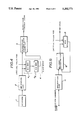
- FIG. 4 is a system block diagram showing an essential part of a transmission system of a facsimile machine applied with the embodiment of the image data compression system according to the present invention.
- FIG. 5 is a system block diagram showing an essential part of a reception system of the facsimile machine applied with the embodiment of the image data compression system according to the present invention.
- FIG. 2 is a diagram for explaining a principle of an image data compression system according to the present invention when transmitting the pattern of the character "A" shown in FIG. 1.
- an arrow indicates inclination change information which is required when transmitting the image data of the pattern.
- Table 3 shows an example of the image data of the pattern of the character "A" shown in FIG. 1 compressed by the image data compression system according to the present invention.
- the code name "V” of the MR (vertical) coding scheme is replaced by a code name "D" to indicate that it is an inclination change code.
- the codes V(0), VR(m) and VL(m) of the MR coding scheme shown in the Table 1 can respectively be used as the inclination change codes D(0), DR(m) and DL(m) of the coding scheme shown in the Table 3.
- each number under the column "No. of Bits" indicates the number of bits for the case where each of the codes shown in the Table 1 are replaced by the inclination change codes used in the present invention.
- FIG. 3 shows an embodiment of the image data compression system according to the present invention.
- the image data compression system comprises a first detecting part 100, a second detecting part 101, and a coding part 102.
- the first detecting part 100 is supplied with an input image data and detects a transition edge of a picture element on a scanning line where the picture element undergoes a transition from white to black or vice versa.
- the second detecting part 101 is coupled to the first detecting part 100 and detects an inclination change quantity between a direction of a transition edge of a picture element on an object scanning line and a direction of a transition edge of a picture element on a reference scanning line which precedes the object scanning line.
- the coding part 102 is coupled to the second detecting part 101 and codes the inclination change quantity into an inclination change code which is output as a compressed image data of the input image data.
- FIG. 4 shows an essential part of a transmission system of the facsimile machine.
- a means is provided to obtain the inclination change code.
- a scanner 1 reads a document image and supplies an image data to an MR coding circuit 2.
- the MR coding circuit 2 codes the image data in conformance with the MR coding scheme and supplies a coded image data related to an object scanning line to an inclination change code generating circuit 3 and a first stage register 4 1 of a first-in-first-out (FIFO) buffer 4 which is made up of two stages of registers 4 1 and 4 2 .
- FIFO first-in-first-out
- the first stage register 4 1 of the FIFO buffer 4 receives a code sequence related to a first scanning line from the MR coding circuit 2, an initial value V(0) is transferred to the second stage register 4 2 because a code corresponding to V(0) is prestored in the first stage register 4 1 as the initial value.
- the code sequence of the previous scanning line that is, the reference scanning line, is transferred to the second stage register 4 2 .
- the inclination change code generating circuit 3 compares the code sequence which is related to the object scanning line and is received from the MR coding circuit 2 and the code sequence which is related to the reference scanning line and is received from the second stage register 4 2 of the FIFO buffer 4. From this comparison, the inclination change code generating circuit 3 obtains a shift quantity (n) of the corresponding MR (vertical) codes V(0), VR(m) and VL(m) and replaces these MR codes by inclinational change codes D(0), DR(n) and DL(n) which correspond to the shift quantity (n), that is, the inclinational change quantity.
- the directional change codes are generated and output from the inclinational change code generating circuit 3 so that the other horizontal codes and the like are maintained as they are.
- the inclinational change code generating circuit 3 comprises a ROM table shown in the following Table 4.
- Table 4 the codes under the columns "Before” and “Now” respectively denote output codes of the FIFO buffer 4 and the MR coding circuit 2.
- the transmission system shown in FIG. 4 is controlled by a central process unit (CPU, not shown), and the access to the ROM table can be controlled by the CPU.
- CPU central process unit
- the CPU can carry out a control to generate a code VR(3) to indicate a mode change code from the MR code to the inclinational change code, and a code VL(3) to indicate a mode change code from the inclinational change code to the MR code.
- the MR coding circuit 2 corresponds to the first detecting part 100 shown in FIG. 3.
- the FIFO buffer 4 and a portion of the direction change code generating circuit 3 correspond to the second detecting part 101.
- a remaining portion of the inclinational change code generating circuit 3 corresponds to the coding part 102.
- FIG. 5 shows an essential part of a reception system of the facsimile machine.
- a means is provided to decode the inclinational change code.
- a reception circuit 11 receives the inclinational change code and supplies the inclinational change code to an MR code decoding circuit 12.
- a code corresponding to V(0) is prestored in a register 13 as an initial value, and this initial value is also supplied to the MR code decoding circuit 12.
- the MR code decoding circuit 12 compares the inclinational change code sequence which is related to the object scanning line and is received from the reception circuit 11 and the MR code sequence which is related to the reference scanning line and is received from the register 13.
- the MR code decoding circuit 12 converts the directional change code into an MR code. This conversion can easily be carried out by adding a shift quantity indicated by the inclinational change codes D(0), DR(m) and DL(m) to the MR (vertical) codes V(0), VR(n) and VL(n).
- a ROM table similar to that shown in the Table 4 may be used to convert the inclinational change code to the MR code.
- the reception system shown in FIG. 5 is controlled by a central process unit (CPU, not shown), and the access to the ROM table can be controlled by the CPU. Further, the CPU can carry out a control responsive to the mode change codes VR(3) and VL(3) described above.
- the MR code sequence obtained in the MR code decoding circuit 12 is stored in the register 13 for use as a code sequence related to a reference scanning line when decoding the next scanning line.
- the MR code sequence obtained in the MR code decoding circuit 12 is supplied to a plotter (not shown), for example, which records a received image.
- the image data transmission employing the image data compression system according to the present invention can be realized by simply adding the FIFO buffer 4 and the inclinational change code generating circuit 3 shown in FIG. 4 to the transmission system of the existing facsimile machine and adding the MR code decoding circuit 12 and the register 13 shown in FIG. 5 to the reception system of the existing facsimile machine. It is thus possible to realize an image data transmission having a high transmission efficiency by making a simple modification of the existing facsimile machine which uses the MR coding scheme.
- the shift quantity of the transition edges of the picture elements on two mutually adjacent scanning lines is a constant value in many cases. Accordingly, the data quantity can be reduced even more notably in the case of a Chinese character (kanji) compared to alpha-numeric characters.
- a inclinational change quantity between a direction of a transition edge of a picture element on an object scanning line and a direction of a transition edge of a picture element on a reference scanning line is coded and transmitted so as to reduce the data (information) quantity which needs to be transmitted.
Abstract
An image data compression system detects from an input image data a transition edge of a picture element on a scanning line where the picture element undergoes a transition from white to black or vice versa. A direction change quantity between a direction of a transition edge of a picture element on an object scanning line and a direction of a transition edge of a picture element on a reference scanning line which precedes the object scanning line is detected, and this direction change quantity is coded into a directional change code which is output as a compressed image data of the input image data.
Description
This application is a continuation of application Ser. No. 07/385,085, filed Jul. 26, 1989 now abandoned.
The present invention generally relates to image data compression systems and facsimile machines employing the image data compression system, and more particularly to an image data compression system which compresses a quantity of data to be transmitted when transmitting image data such as characters and patterns and a facsimile machine employing the image data compression system.
A modified READ (MR) coding scheme is used as a standard two-dimensional data compression system of facsimile machines. A description will be given of a case where a character "A" having a pattern shown in FIG. 1 is coded by the MR coding scheme.
For the sake of convenience, FIG. 1 shows a screen having 16 picture elements along a horizontal axis (X-axis) and 11 picture elements along a vertical axis (Y-axis). It is assumed that picture elements constituting a column on the right of a rightmost column within the screen are all black picture elements as indicated by a hatching.
The pattern of the character "A" is developed on the screen as a graphic, and MR codes shown in the following Table 1 are obtained by scanning this screen in the direction of the X-axis.
              TABLE 1
______________________________________
Line No. Code Sequence       No. of Bits
______________________________________
1        V(0)                1
2        H{W(7)B(2)}V(0)     10
3        V(0)V(0)V(0)        3
4        VL(1)VR(1)V(0)      7
5        VL(1)VR(1)V(0)      7
6        VL(1)H{B(3)W(2)}VR(1)V(0)
                             16
7        VL(1)VL(1)VR(1)VR(1)V(0)
                             13
8        VL(1)PVR(1)V(0)     11
9        VL(1)H{B(4)W(6)}VR(1)V(0)
                             17
10       V(0)VL(1)VR(1)V(0)V(0)
                             9
11       PP                  8
______________________________________
The MR code is basically a vertical code. The MR coding scheme codes a shift quantity of an X-axis address of a transition point where a picture element undergoes a transition from white to black or black to white on a present scanning line which is being processed when compared with an X-axis address of a transition point where a picture element undergoes a transition from white to black or black to white on a previous scanning line which is immediately prior to the present scanning line.
In the Table 1, a value m in brackets "( )" indicates the shift quantity, where m≧3. Hence, V(0) indicates that there is no shift. On the other hand, VR(m) and VL(m) respectively indicate shifts to the right and left. In addition, H indicates that a modified Huffman (MH) coding scheme is applied. The MH coding scheme is used when the shift quantity is greater than "3" and a new pair of transition points where the picture element undergoes a transition from white to black or black to white is generated. W(p) and B(p) of the MH code respectively indicate that p consecutive picture elements are white and p consecutive picture elements are black. P indicates that two codes forming a pair are deleted.
Each number under the column "No. of Bits" in the Table 1 indicates a total number of bits of the corresponding code sequence under the column "Code Sequence". The following Table 2 shows the correspondence of the codes and the number of bits.
              TABLE 2
______________________________________
Code Name     Code            No. of Bits
______________________________________
Pass    P         0001            4
MH Code H         001+MH(p1)+MH(p2)
                                  3+(H1+H2)
MR Code V(0)      1               1
        VR(1)     011             3
        VR(2)     000011          6
        VR(3)     0000011         7
        VL(1)     010             3
        VL(2)     000010          6
        VL(3)     0000010         7
______________________________________
In the Table 2, second and third terms under the column "Code" of the MH code respectively are MR codes indicating the numbers of consecutive white picture elements and consecutive black picture elements.
In a general graphic, the shift quantity of the X-axis address of the transition point of the picture element is in many cases constant and continuous. For example, in the case of the character "A" shown in FIG. 1, the shift quantity is 0 or ±1 and the same shift quantity such as ±1 continues between many scanning lines.
However, as described above, the MR code is basically a vertical code. The MR coding scheme codes a shift quantity of an X-axis address of a transition point (or edge) where a picture element undergoes a transition from white to black or black to white on an object scanning line when compared with an X-axis address of a transition point (or edge) where a picture element undergoes a transition from white to black or black to white on a reference scanning line. For this reason, when transmitting the image data, it is necessary to transmit two kinds of data respectively indicating a value of the shift quantity (that is, a difference between the X-axis addresses) and a direction of the shift. Therefore, there is a problem in that there is a limit to further reducing a quantity of data which needs to be transmitted when making an image data transmission.
Accordingly, it is a general object of the present invention to provide a novel and useful image data compression system and a facsimile machine employing the image data compression system in which the problems described above are eliminated.
Another and more specific object of the present invention is to provide an image data compression system comprising first detecting means supplied with an input image data for detecting a transition edge of a picture element on a scanning line where the picture element undergoes a transition from white to black or vice versa, second detecting means coupled to the first detecting means for detecting an inclination change quantity between a direction of a transition edge of a picture element on an object scanning line and a direction of a transition edge of a picture element on a reference scanning line which precedes the object scanning line, and coding means coupled to the second detecting means for coding the inclination change quantity into an inclination change code which is output as a compressed image data of the input image data. According to the image data compression system of the present invention, it is possible to obtain a high data compression rate by noting that the shift quantity of the transition points of the picture elements on two mutually adjacent scanning lines is constant in many cases.
Still another object of the present invention is to provide a facsimile machine comprising reading means for reading a document image and outputting an input image data, first detecting means supplied with the input image data for detecting a transition edge of a picture element on a scanning line where the picture element undergoes a transition from white to black or vice versa, second detecting means coupled to the first detecting means for detecting an inclination change quantity between a direction of a transition edge of a picture element on an object scanning line and a direction of a transition edge of a picture element on a reference scanning line which precedes the object scanning line, and coding means coupled to the second detecting means for coding the inclination change quantity into a directional change code which is output as a compressed image data of the input image data. According to the facsimile machine of the present invention, it is possible to effectively improve the compression rate of the existing facsimile machine by making a simple modification.
Other objects and further features of the present invention will be apparent from the following detailed description when read in conjunction with the accompanying drawings.
FIG. 1 shows an example of a graphic on a screen which is subjected to a data compression when making an image data transmission;
FIG. 2 is a diagram for explaining a principle of an image data compression system according to the present invention;
FIG. 3 is a system block diagram showing an embodiment of the image data compression system according to the present invention;
FIG. 4 is a system block diagram showing an essential part of a transmission system of a facsimile machine applied with the embodiment of the image data compression system according to the present invention; and
FIG. 5 is a system block diagram showing an essential part of a reception system of the facsimile machine applied with the embodiment of the image data compression system according to the present invention.
FIG. 2 is a diagram for explaining a principle of an image data compression system according to the present invention when transmitting the pattern of the character "A" shown in FIG. 1. In FIG. 2, an arrow indicates inclination change information which is required when transmitting the image data of the pattern. When a direction of a transition edge (indicated by a bold vertical line) of a picture element on a reference scanning line and a direction of the transition edge of the picture element on an object scanning line are different, it is necessary to transmit inclination change information corresponding to the arrow indicated by a solid line. On the other hand, when the direction of the transition edge of the picture element on the reference scanning line and the direction of the transition edge of the picture element on the object scanning line are the same, it is sufficient to transmit an information indicating that there is no change in the inclination of the transition edge as indicated by a phantom arrow. For example, a code D(0) which is assigned a minimum code length as will be described later may be transmitted as the information indicating that there is no change in the inclination of the transition edge. There is no need to transmit two kinds of data respectively indicating a value of the shift quantity (that is, a difference between the X-axis addresses) of the transition edge of the picture element and a direction of the shift as in the case of the MR coding scheme.
The following Table 3 shows an example of the image data of the pattern of the character "A" shown in FIG. 1 compressed by the image data compression system according to the present invention.
              TABLE 3
______________________________________
Line No. Code Sequence       No. of Bits
______________________________________
1        D(0)                 1
2        H{W(7)B(2)}D(0)     10
3        D(0)D(0)D(0)         3
4        DL(1)DR(1)D(0)       7
5        D(0)D(0)D(0)         7
6        D(0)H{B(3)W(2)}D(0)D(0)
                             16
7        D(0)DL(1)DR(1)D(0)D(0)
                             13
8        D(0)PD(0)D(0)       11
9        D(0)H{B(4)W(6)}D(0)D(0)
                             17
10       DR(1)DL(1)DR(1)DL(1)D(0)
                             13
11       PP                   8
______________________________________
In the Table 3, the code name "V" of the MR (vertical) coding scheme is replaced by a code name "D" to indicate that it is an inclination change code. The codes V(0), VR(m) and VL(m) of the MR coding scheme shown in the Table 1 can respectively be used as the inclination change codes D(0), DR(m) and DL(m) of the coding scheme shown in the Table 3. In the Table 3, each number under the column "No. of Bits" indicates the number of bits for the case where each of the codes shown in the Table 1 are replaced by the inclination change codes used in the present invention.
A total number of bits under the column "No. of Bits" in the Table 3 is "85" as opposed to "102" in the Table 1. Since 102/85=1.2, it is readily seen that the transmission efficiency is improved by 20% according to the present invention. The compression rate in the present invention for the pattern shown in FIG. 1 is (16×11)/85=2.1 and is considerably improved compared to (16×11)/102=1.73 obtained by the MR coding scheme.
FIG. 3 shows an embodiment of the image data compression system according to the present invention. The image data compression system comprises a first detecting part 100, a second detecting part 101, and a coding part 102. The first detecting part 100 is supplied with an input image data and detects a transition edge of a picture element on a scanning line where the picture element undergoes a transition from white to black or vice versa. The second detecting part 101 is coupled to the first detecting part 100 and detects an inclination change quantity between a direction of a transition edge of a picture element on an object scanning line and a direction of a transition edge of a picture element on a reference scanning line which precedes the object scanning line. The coding part 102 is coupled to the second detecting part 101 and codes the inclination change quantity into an inclination change code which is output as a compressed image data of the input image data.
Next, a description will be given of a facsimile machine which is applied with the embodiment of the image data compression system according to the present invention which uses the inclination change code.
FIG. 4 shows an essential part of a transmission system of the facsimile machine. In addition to the known means constituting the transmission system of the facsimile machine, a means is provided to obtain the inclination change code. As in the case of an existing facsimile machine, a scanner 1 reads a document image and supplies an image data to an MR coding circuit 2. The MR coding circuit 2 codes the image data in conformance with the MR coding scheme and supplies a coded image data related to an object scanning line to an inclination change code generating circuit 3 and a first stage register 41 of a first-in-first-out (FIFO) buffer 4 which is made up of two stages of registers 41 and 42.
When the first stage register 41 of the FIFO buffer 4 receives a code sequence related to a first scanning line from the MR coding circuit 2, an initial value V(0) is transferred to the second stage register 42 because a code corresponding to V(0) is prestored in the first stage register 41 as the initial value. In addition, when the image data related to second and subsequent scanning lines are supplied to the first stage register 41, the code sequence of the previous scanning line, that is, the reference scanning line, is transferred to the second stage register 42.
The inclination change code generating circuit 3 compares the code sequence which is related to the object scanning line and is received from the MR coding circuit 2 and the code sequence which is related to the reference scanning line and is received from the second stage register 42 of the FIFO buffer 4. From this comparison, the inclination change code generating circuit 3 obtains a shift quantity (n) of the corresponding MR (vertical) codes V(0), VR(m) and VL(m) and replaces these MR codes by inclinational change codes D(0), DR(n) and DL(n) which correspond to the shift quantity (n), that is, the inclinational change quantity. The directional change codes are generated and output from the inclinational change code generating circuit 3 so that the other horizontal codes and the like are maintained as they are.
For example, the inclinational change code generating circuit 3 comprises a ROM table shown in the following Table 4. In the Table 4, the codes under the columns "Before" and "Now" respectively denote output codes of the FIFO buffer 4 and the MR coding circuit 2. The codes under the columns "Result" and "Code" respectively denote the inclinational change code which is generated and the corresponding code which is output from the inclinational change code generating circuit 3. For example, the transmission system shown in FIG. 4 is controlled by a central process unit (CPU, not shown), and the access to the ROM table can be controlled by the CPU. Further, the CPU can carry out a control to generate a code VR(3) to indicate a mode change code from the MR code to the inclinational change code, and a code VL(3) to indicate a mode change code from the inclinational change code to the MR code.
              TABLE 4
______________________________________
Before      Now        Result     Code
______________________________________
VR(1)       VR(1)      D(0)       V(0)
            V(0)       DL(1)      VL(1)
            VL(1)      DL(2)      VL(2)
V(0)        VR(1)      DR(1)      VR(1)
            V(0)       D(0)       V(0)
            VL(1)      DL(1)      VL(1)
VL(1)       VR(1)      DR(2)      VR(2)
            V(0)       DR(1)      VR(1)
            VL(1)      DR(0)      VR(0)
Else        Else       MR         MR
______________________________________
In FIG. 4, the MR coding circuit 2 corresponds to the first detecting part 100 shown in FIG. 3. The FIFO buffer 4 and a portion of the direction change code generating circuit 3 correspond to the second detecting part 101. In addition, a remaining portion of the inclinational change code generating circuit 3 corresponds to the coding part 102.
FIG. 5 shows an essential part of a reception system of the facsimile machine. In addition to the known means constituting the reception system of the facsimile machine, a means is provided to decode the inclinational change code. A reception circuit 11 receives the inclinational change code and supplies the inclinational change code to an MR code decoding circuit 12. A code corresponding to V(0) is prestored in a register 13 as an initial value, and this initial value is also supplied to the MR code decoding circuit 12. The MR code decoding circuit 12 compares the inclinational change code sequence which is related to the object scanning line and is received from the reception circuit 11 and the MR code sequence which is related to the reference scanning line and is received from the register 13. By this comparison, the MR code decoding circuit 12 converts the directional change code into an MR code. This conversion can easily be carried out by adding a shift quantity indicated by the inclinational change codes D(0), DR(m) and DL(m) to the MR (vertical) codes V(0), VR(n) and VL(n).
For example, a ROM table similar to that shown in the Table 4 may be used to convert the inclinational change code to the MR code. For example, the reception system shown in FIG. 5 is controlled by a central process unit (CPU, not shown), and the access to the ROM table can be controlled by the CPU. Further, the CPU can carry out a control responsive to the mode change codes VR(3) and VL(3) described above.
The MR code sequence obtained in the MR code decoding circuit 12 is stored in the register 13 for use as a code sequence related to a reference scanning line when decoding the next scanning line. In addition, the MR code sequence obtained in the MR code decoding circuit 12 is supplied to a plotter (not shown), for example, which records a received image.
As may be seen from FIGS. 4 and 5, the image data transmission employing the image data compression system according to the present invention can be realized by simply adding the FIFO buffer 4 and the inclinational change code generating circuit 3 shown in FIG. 4 to the transmission system of the existing facsimile machine and adding the MR code decoding circuit 12 and the register 13 shown in FIG. 5 to the reception system of the existing facsimile machine. It is thus possible to realize an image data transmission having a high transmission efficiency by making a simple modification of the existing facsimile machine which uses the MR coding scheme.
As may be seen from FIG. 1, in a character or pattern, the shift quantity of the transition edges of the picture elements on two mutually adjacent scanning lines is a constant value in many cases. Accordingly, the data quantity can be reduced even more notably in the case of a Chinese character (kanji) compared to alpha-numeric characters.
Therefore, in the present invention, a inclinational change quantity between a direction of a transition edge of a picture element on an object scanning line and a direction of a transition edge of a picture element on a reference scanning line is coded and transmitted so as to reduce the data (information) quantity which needs to be transmitted. In addition, it is possible to further reduce the data quantity which needs to be transmitted by assigning a minimum number of bits for a code which is transmitted when a shift quantity between the transition edges of the picture elements on the two mutually adjacent scanning lines is the same.
Further, the present invention is not limited to these embodiments, but various variations and modifications may be made without departing from the scope of the present invention.
Claims (10)
1. An image data compression system comprising:
first detecting means supplied with an input image data for detecting a transition edge of a picture element on a scanning line where the picture element undergoes a transition from white to black or vice versa;
second detecting means coupled to said first detecting means for detecting any change in the inclination which is denominated as a inclination change quantity between a direction of a transition edge of a picture element on an object scanning line and a direction of a transition edge of a picture element on a reference scanning line which precedes said object scanning line; and
coding means coupled to said second detecting means for coding said direction change quantity into a inclination change code which is output as a compressed image data of said input image data.
2. The image data compression system as claimed in claim 1 wherein said coding means generates as said inclination change code a code V(0) of a modified READ coding scheme when said inclination change quantity is zero and generates codes VR(n) and VL(n) of the modified READ coding scheme when said inclination change quantity is ±n, where V(0) indicates that a shift quantity of a horizontal address of the transition edge on the object scanning line when compared with a horizontal address of the transition edge on the reference scanning line is zero, VR(n) indicates a shift quantity n to the right of an image described by said input image data and VL(n) indicates a shift quantity n to the left of the image described by said input image data.
3. The image transmission system as claimed in claim 1 wherein said first and second means generate a vertical code with respect to said object scanning line and a vertical code with respect to said reference scanning line, said coding means generating said inclinational change code by coding a difference between the vertical code with respect to said object scanning line and the vertical code with respect to said reference scanning line.
4. The image data compression system as claimed in claim 3 wherein said vertical code is a modified READ code.
5. A facsimile machine comprising:
reading means for reading a document image and outputting an input image data;
first detecting means supplied with said input image data for detecting a transition edge of a picture element on a scanning line where the picture element undergoes a transition from white to black or vice versa;
second detecting means coupled to said first detecting means for detecting any change in the inclination which is denominated as a inclination change quantity between a direction of a transition edge of a picture element on an object scanning line and a direction of a transition edge of a picture element on a reference scanning line which precedes said object scanning line; and
coding means coupled to said second detecting means for coding said direction change quantity into a inclination change code which is output as a compressed image data of said input image data.
6. The facsimile machine as claimed in claim 5 wherein said coding means generates as said inclinational change code a code V(0) of a modified READ coding scheme when said inclination change quantity is zero and generates codes VR(n) and VL(n) of the modified READ coding scheme when said inclination change quantity is ±n, where V(0) indicates that a shift quantity of a horizontal address of the transition edge on the object scanning line when compared with a horizontal address of the transition edge on the reference scanning line is zero, VR(n) indicates a shift quantity n to the right of an image described by said input image data and VL(n) indicates a shift quantity n to the left of the image described by said input image data.
7. The image transmission system as claimed in claim 5 wherein said first and second means generate a vertical code with respect to said object scanning line and a vertical code with respect to said reference scanning line, said coding means generating said inclinational change code by coding a difference between the vertical code with respect to said object scanning line and the vertical code with respect to said reference scanning line.
8. The image data compression system as claimed in claim 7 wherein said vertical code is a modified READ code.
9. The facsimile machine as claimed in claim 5 wherein said first detecting means comprises a modified READ coding circuit.
10. The facsimile machine as claimed in claim 9 wherein said second detecting means includes register means coupled to said first detecting means for storing the transition edge of the reference scanning line.
Priority Applications (1)
| Application Number | Priority Date | Filing Date | Title |
|---|---|---|---|
| US07/742,534 US5202771A (en) | 1988-08-08 | 1991-08-08 | Image data compression system and facsimile machine employing the image data compression system |
Applications Claiming Priority (4)
| Application Number | Priority Date | Filing Date | Title |
|---|---|---|---|
| JP63-196126 | 1988-08-08 | ||
| JP19612688A JPH0246068A (en) | 1988-08-08 | 1988-08-08 | Picture data compressing system and facsimile equipment applying same |
| US38508589A | 1989-07-26 | 1989-07-26 | |
| US07/742,534 US5202771A (en) | 1988-08-08 | 1991-08-08 | Image data compression system and facsimile machine employing the image data compression system |
Related Parent Applications (1)
| Application Number | Title | Priority Date | Filing Date |
|---|---|---|---|
| US38508589A Continuation | 1988-08-08 | 1989-07-26 |
Publications (1)
| Publication Number | Publication Date |
|---|---|
| US5202771A true US5202771A (en) | 1993-04-13 |
Family
ID=27327192
Family Applications (1)
| Application Number | Title | Priority Date | Filing Date |
|---|---|---|---|
| US07/742,534 Expired - Fee Related US5202771A (en) | 1988-08-08 | 1991-08-08 | Image data compression system and facsimile machine employing the image data compression system |
Country Status (1)
| Country | Link |
|---|---|
| US (1) | US5202771A (en) |
Cited By (4)
| Publication number | Priority date | Publication date | Assignee | Title |
|---|---|---|---|---|
| US5473444A (en) * | 1992-10-15 | 1995-12-05 | Ricoh Company, Ltd. | Image processing device having function of detecting dotted-image area |
| US5745606A (en) * | 1995-10-11 | 1998-04-28 | Yoshimichi; Kanda | Method and system for storing information in compressed block data |
| US5986772A (en) * | 1996-06-29 | 1999-11-16 | Samsung Electronics Co., Ltd. | Technique for automatically controlling resolution |
| US6728412B1 (en) | 1999-10-29 | 2004-04-27 | S.V.V. Technology Innovations, Inc. | Method and apparatus for on-the-fly image coding |
Citations (2)
| Publication number | Priority date | Publication date | Assignee | Title |
|---|---|---|---|---|
| US4839738A (en) * | 1987-04-22 | 1989-06-13 | Advanced Micro Devices, Inc. | Apparatus for decoding facsimile coded data to image data with coding and reference line windowing and color change detection |
| US4860114A (en) * | 1986-11-29 | 1989-08-22 | Hitachi, Ltd. | Method and apparatus for expanding two-dimensional compressional code |
-
1991
- 1991-08-08 US US07/742,534 patent/US5202771A/en not_active Expired - Fee Related
Patent Citations (2)
| Publication number | Priority date | Publication date | Assignee | Title |
|---|---|---|---|---|
| US4860114A (en) * | 1986-11-29 | 1989-08-22 | Hitachi, Ltd. | Method and apparatus for expanding two-dimensional compressional code |
| US4839738A (en) * | 1987-04-22 | 1989-06-13 | Advanced Micro Devices, Inc. | Apparatus for decoding facsimile coded data to image data with coding and reference line windowing and color change detection |
Cited By (4)
| Publication number | Priority date | Publication date | Assignee | Title |
|---|---|---|---|---|
| US5473444A (en) * | 1992-10-15 | 1995-12-05 | Ricoh Company, Ltd. | Image processing device having function of detecting dotted-image area |
| US5745606A (en) * | 1995-10-11 | 1998-04-28 | Yoshimichi; Kanda | Method and system for storing information in compressed block data |
| US5986772A (en) * | 1996-06-29 | 1999-11-16 | Samsung Electronics Co., Ltd. | Technique for automatically controlling resolution |
| US6728412B1 (en) | 1999-10-29 | 2004-04-27 | S.V.V. Technology Innovations, Inc. | Method and apparatus for on-the-fly image coding |
Similar Documents
| Publication | Publication Date | Title |
|---|---|---|
| US4682215A (en) | Coding system for image processing apparatus | |
| US4829385A (en) | Data communication apparatus | |
| US4688100A (en) | Video data encoding/decoding apparatus | |
| US4809081A (en) | Method and apparatus for decompressing encoded data | |
| US5751233A (en) | Decoding apparatus and method therefor | |
| EP0288219B1 (en) | Apparatus for decoding facsimile coded data to image data | |
| US4618846A (en) | Data coding | |
| US5202771A (en) | Image data compression system and facsimile machine employing the image data compression system | |
| US5579412A (en) | Image processing apparatus | |
| EP0229379A2 (en) | Digital picture signal coding/decoding circuit | |
| EP0746143B1 (en) | A method of and system for compressing and decompressing digital image signals | |
| KR930006750B1 (en) | Coding appalatus of video data | |
| US4972497A (en) | Image coding system | |
| JPS60154776A (en) | Coding and decoding system | |
| GB2222739A (en) | Image data compression system and facsimile machine employing the image data compression system | |
| US7072078B2 (en) | Image storage apparatus, image storage method, and storage medium | |
| US5243435A (en) | Method of decoding MR codes of continuous vertical mode data for the same change points | |
| JP3433276B2 (en) | Image signal compression method and apparatus, image signal decompression method and apparatus, image signal compression / decompression method and apparatus, and printer | |
| US4716467A (en) | Speed-up method and apparatus for two-dimensional facsimile coding and decoding | |
| US5327253A (en) | Facsimile transmission method | |
| JP2001102937A (en) | Method and device for run-length encoding | |
| JP3159811B2 (en) | Demodulator | |
| JPH03136575A (en) | Facsimile coder | |
| JPS60182875A (en) | Picture data compressing circuit | |
| JPS6231257A (en) | Two-dimensional encoding device for picture signal |
Legal Events
| Date | Code | Title | Description |
|---|---|---|---|
| FEPP | Fee payment procedure |
Free format text: PAYOR NUMBER ASSIGNED (ORIGINAL EVENT CODE: ASPN); ENTITY STATUS OF PATENT OWNER: LARGE ENTITY |
|
| AS | Assignment |
Owner name: RICOH COMPANY, LTD., JAPAN Free format text: ASSIGNMENT OF ASSIGNORS INTEREST.;ASSIGNOR:MURAYAMA, NOBORU;REEL/FRAME:006355/0699 Effective date: 19890720 |
|
| FPAY | Fee payment |
Year of fee payment: 4 |
|
| REMI | Maintenance fee reminder mailed | ||
| LAPS | Lapse for failure to pay maintenance fees | ||
| FP | Lapsed due to failure to pay maintenance fee |
Effective date: 20010413 |
|
| STCH | Information on status: patent discontinuation |
Free format text: PATENT EXPIRED DUE TO NONPAYMENT OF MAINTENANCE FEES UNDER 37 CFR 1.362 |