US5201574A - Cleat retaining bolt and nut for vehicle endless track - Google Patents
Cleat retaining bolt and nut for vehicle endless track Download PDFInfo
- Publication number
- US5201574A US5201574A US07/844,769 US84476992A US5201574A US 5201574 A US5201574 A US 5201574A US 84476992 A US84476992 A US 84476992A US 5201574 A US5201574 A US 5201574A
- Authority
- US
- United States
- Prior art keywords
- grouser
- nut
- bolt
- cleat
- belt
- Prior art date
- Legal status (The legal status is an assumption and is not a legal conclusion. Google has not performed a legal analysis and makes no representation as to the accuracy of the status listed.)
- Expired - Fee Related
Links
Images


Classifications
-
- B—PERFORMING OPERATIONS; TRANSPORTING
- B62—LAND VEHICLES FOR TRAVELLING OTHERWISE THAN ON RAILS
- B62D—MOTOR VEHICLES; TRAILERS
- B62D55/00—Endless track vehicles
- B62D55/08—Endless track units; Parts thereof
- B62D55/18—Tracks
- B62D55/26—Ground engaging parts or elements
Definitions
- the field of the invention is endless track assemblies for snow grooming vehicles, and more particularly the cleat assemblies thereof, including structures for fastening the cleats to the flexible plastic belting of such tracks.
- Snow groomer vehicles use endless tracks made up of flexible plastic belts made continuous by lacing their ends together. Actual lacing thread may be used, although lacing joint assemblies are more commonly employed, being a combination of metallic hinge plates and an associated hinge pin.
- the snow grooming vehicle commonly has an endless track assembly on each of its sides, each comprising a number of fabric reinforced plastic belts. The belts are spaced apart to provide a broad base for the track while utilizing minimum amounts of belting. Steel cleat assemblies are bolted across the individual belts at intervals, tieing them together into a track assembly. Each assemblied track is engaged by a power-transmitting sprocket wheel, which forces the belts to travel together around a set of guiding wheels called bogies.
- the powered belt imparts horizontal shear forces to the cleats, which engage the snow to propel the vehicle.
- Extensive development has gone into the design of the elongate cleat members, with the objectives of providing maximum forward traction, along with substantial resistance to side slipping.
- Cleat constructions are disclosed in U.S. Pat. Nos. 3,765,731, 4,560,211, 4,281,882 and 4,059,315.
- the ground contacting cleat also called a "grouser”
- bolts and nut assemblies installed in matching holes in the grouser, the belt, and a metal backing plate on the inside of the belt. A large number of bolt and nut assemblies are required to spread the high shearing forces among the belt holes.
- the horizontal force on the ground engaging part of the cleat also results in high moment loads which must be resisted by the stems of the bolts. Failure of the bolts in bending is a too frequent common occurrence, and is largely caused by the moment force applied to the portion of the stem at the junction of the threads and the unthreaded shank, resulting in stress concentration.
- a cleat assembly design of greater strength is needed, particularly incorporating a bolt and nut assembly not susceptible to bending fracture at the threaded portions.
- a nut retaining member is used in conjunction with the inventive bolt and not combination.
- a downwardly opening channel is provided, with bores spaced apart through its web to receive the mounting bolts and the upper portion of the nut.
- Downstanding channel legs carry a pair of opposed inward projections at each clearance hole.
- the bottom portion of the corresponding mounting nuts are preferably square, and each has a pair of opposed parallel faces, each carrying a depression placed to accept the inward projections of the channel legs.
- the nuts are forcibly inserted into the channel and each retained in proper location for engagement by the corresponding mounting bolt.
- a single workman may install the entire cleat assembly by applying appropriate tools only to the bolt heads on the side of the belt opposite the grouser plate.
- the nut retaining channel, with properly spaced nuts is inserted as a unit through one of the open ends of the closed box grouser plate. Proportioned to avoid contact with the grouser plate, the channel carries no clamping load and need not be highly hardened.
- the cleat assembly may utilize a grouser plate in structurally strong closed box form, the need for direct access to each individual mounting nut being eliminated.
- FIG. 1 is a perspective representation of an endless track vehicle incorporating the cleat nut and bolt of the invention, drawn to a reduced scale,
- FIG. 2 a cross sectional view of the endless track of FIG. 1, taken along line 2--2 thereof, drawn to a reduced scale larger than that of FIG. 1,
- FIG. 3 a top plan view of a fragment of the endless track of FIG. 1, drawn to a reduced scale slightly smaller that of FIG. 2,
- FIG. 4 a plan view of a fragment of one of the individual flexible belts of the endless track of FIG. 1 showing the belt lacing joint of one of the belts thereof, drawn to a reduced scale somewhat larger than that of FIG. 2,
- FIG. 5 a vertical cross sectional view of the lacing joint of FIG. 4, taken along line 5--5 thereof, drawn to the same scale,
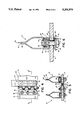
- FIG. 6 a cross sectional view of a fragment of the endless track of FIG. 1, taken along line 6--6 of FIG. 2, drawn to substantially full scale,
- FIG. 7 a perspective view of a fragment of the torque nut retaining channel of the invention, drawn to approximately one-half full scale
- FIG. 8 a plan view of the torquing nut of the invention, drawn to full scale
- FIG. 9 a cross sectional view of the torquing nut of FIG. 8, taken along line 9--9 thereof, drawn to the same scale,
- FIG. 10 a cross sectional view of the nut retaining channel of FIG. 7, taken along line 10--10 thereof, drawn to an enlarged scale,
- FIG. 11 a cross sectional view of a fragment of a prior art endless track assembly, drawn to approximately the scale of FIG. 6,
- FIG. 12 a side view of the bolt of the bolt and nut combination of the invention, drawn to substantially full scale
- FIG. 13 a vertical cross sectional view of the nut of the bolt and nut combination of the invention, drawn to the scale of FIG. 12,
- FIG. 14 a bottom view of the nut of FIG. 13, taken along line 14--14 thereof, drawn to the same scale, and
- FIG. 15 a cross sectional view of a fragment of the endless track of FIG. 1, showing a cleat assembled upon the belting of the track, incorporating the inventive cleat retaining bolt and nut, drawn to substantially full scale.
- FIG. 1 An endless belt track, with a multiplicity of cleat assemblies 10 in accordance with the invention, is shown in FIG. 1 installed upon an off-road vehicle 11.
- Vehicle 11 may, for example, be used to propel a snow tiller dr other ski run grooming implement.
- the track assembly 12 comprises a number of belts 13 of flexible fiber reinforced plastic secured spaced apart by the laterally directed cleat assemblies 10. Lacing assemblies 14 connect opposing ends of each belt 13, making track 12 endless.
- Track 12 is supported on the vehicle by wheels 15, one being a drive sprocket engaging the cleats 10.
- Each cleat 10 has a ground engaging, shaped plate 16 called a grouser.
- Grousers 16 have been employed in many configurations, each calculated to provide improved traction with the snow, prevent side slip of the vehicle, or otherwise perform more desirably and efficiently.
- the present invention is not concerned primarily with traction developing qualities, but with improved methods for fastening the grousers to the belts 13.
- the fastening provisions of the invention also permit greater freedom in grouser design, as explained below.
- Illustrated track 12 has three inside belting strips 13 used with a pair of narrower outside strips 13.
- Lateral inside grouser plates 16i are secured to the three inside belts 13 by bolts 17.
- Outside grouser plates 16o are bolted spanning the pair of outside belts 13 and the centermost two of the inside belts 13, laterally overlapping inside grousers 16i.
- Wheel guide assemblies 18 are bolted projecting from the overlapping grouser portions between belts 13.
- Belt ends 18, shown free in FIG. 3, are in fact attached by lacing hinge assemblies 19.
- Hinge plates 20 are bolted through holes, not shown, in the belt ends, and are connected by a hinge pin 21.
- Bolts 17 are sometimes used to secure both the hinge plate 20 and one of the grouser plates 16.
- Grouser plate 16 is "U" shaped at the belts 13 and bolts 17, with side portions formed to meet at full length welds 23. It is possible to utilize this extremely rigid, strong box construction because, as will be evident from the following, access to the individual grouser mounting bolts is not necessary. Spaced apart grouser mounting holes 24 mate with corresponding belt mounting holes 25.
- a belt backing plate 26 extends laterally across each belt strip, preferably stiffened by downwardly bent edge portions 28, avoiding damage to the flexing belt structure.
- hardened locking washer 29 accompanies each hardened mounting bolt 17, helping to withstall any loosening from long term creep of the material of belts 13.
- a downwardly opening elongate channel member 30 Inside each box grouser 16, extending its full length, is a downwardly opening elongate channel member 30.
- a torquing nut 31 is prepositioned at each mounting bolt location, secured within channel legs 32.
- Opposing pairs of inwardly projecting dimples 33 engage matching depressions 34 in opposing, parallel, side faces 35 of each nut. (FIGS. 8 and 9)
- each grouser 16 is placed across appropriate associated belts with the grouser mounting holes 24 in alignment with belt mounting holes 25. Then, channel 30 with spaced nuts 31, is inserted through an open grouser end 36 with the nuts each aligned with belt and grouser mounting holes The mounting bolts 17 are then installed through backing plates 26, belts 13 and grousers 16 to engage the threads of torquing nuts 31. In practice. It is advantageous to first engage tire guide bolts 17g, to firmly position channel and nuts upon the grousers, before attempting to align and engage the belt securing bolts 17.
- the nut depressions 34 are preferably sized to allow nuts 31 to float a small amount for alignment with bolts 17. Nut rotation during cleat assembly is resisted by channel legs 32. (FIG. 7) Bolt clearance hole 37 in the channel web 38 isolates channel 30 from the vehicle driving load resisting cleat structure. Channel 30 does not contact grouser 16, while nuts, bolts, grouser and belt are all in forcible frictional contact. Accordingly, channel 30 may be of unhardened, unalloyed steel.
- the mounting bolts 17, and associated nuts 31 are replaced in cleat 10 by lengthened bolts and nuts 39 and 40 respectively.
- FIG. 6 use of bolt 17 along with nut 31 places the bolt threads 41 dangerously near the position of maximum bending moment upon bolt 17. The bending moment is imposed by the horizontal shear load upon grouser 16 during operation of the vehicle, and is near maximum near grouser mounting holes 24. Accordingly, fracture of bolt 17 at the juncture of threads 41 and unthreaded shank 42 sometimes results in practice. In contrast, use of the long, unthreaded shank, bolt 39 with nut 40 places the bolt threads 43 distantly from this position.
- Lengthened nut 40 has a bore 44 with a threaded portion 43 only at its end distant from the grouser-belt interface, which is joined with an unthreaded, smooth bolt clearing portion 45.
- a hardened lock washer 29 is preferably employed between bolt head 46 and backing plate 26.
- a locking compound is preferably used upon the mating bolt and nut threads.
- a nut retaining channel 30 is preferably provided to facilitate the assembly of the cleat 10 upon the belt 13. However, channel 30 in this instance provides clearing holes 47 for the upper portion 48 of long nut 40, while channel legs 32 extend downward about opposing sides of a lowermost, square portion 49 in contact with grouser 16. Again, dimples 33 are provided in the downstanding legs, along with matching bolt head depressions 34.
Abstract
Description
Claims (3)
Priority Applications (5)
| Application Number | Priority Date | Filing Date | Title |
|---|---|---|---|
| US07/844,769 US5201574A (en) | 1992-03-02 | 1992-03-02 | Cleat retaining bolt and nut for vehicle endless track |
| PCT/US1993/001147 WO1993017903A1 (en) | 1992-03-02 | 1993-02-10 | Cleat retaining bolt and nut for vehicle endless track |
| EP93904993A EP0628001A4 (en) | 1992-03-02 | 1993-02-10 | Cleat retaining bolt and nut for vehicle endless track. |
| CA002130908A CA2130908A1 (en) | 1992-03-02 | 1993-02-10 | Cleat retaining bolt and nut for vehicle endless track |
| JP5515675A JPH07508237A (en) | 1992-03-02 | 1993-02-10 | Cleat retaining bolts and nuts for vehicle tracks |
Applications Claiming Priority (1)
| Application Number | Priority Date | Filing Date | Title |
|---|---|---|---|
| US07/844,769 US5201574A (en) | 1992-03-02 | 1992-03-02 | Cleat retaining bolt and nut for vehicle endless track |
Publications (1)
| Publication Number | Publication Date |
|---|---|
| US5201574A true US5201574A (en) | 1993-04-13 |
Family
ID=25293583
Family Applications (1)
| Application Number | Title | Priority Date | Filing Date |
|---|---|---|---|
| US07/844,769 Expired - Fee Related US5201574A (en) | 1992-03-02 | 1992-03-02 | Cleat retaining bolt and nut for vehicle endless track |
Country Status (5)
| Country | Link |
|---|---|
| US (1) | US5201574A (en) |
| EP (1) | EP0628001A4 (en) |
| JP (1) | JPH07508237A (en) |
| CA (1) | CA2130908A1 (en) |
| WO (1) | WO1993017903A1 (en) |
Cited By (10)
| Publication number | Priority date | Publication date | Assignee | Title |
|---|---|---|---|---|
| US5354124A (en) * | 1993-09-07 | 1994-10-11 | Lmc Operating Corp. | Water sealed, cable reinforced vehicle endless track and cleat assembly |
| EP0646518A1 (en) * | 1993-10-01 | 1995-04-05 | Arnold Jäger | Track for tracked vehicles, especially snow vehicles |
| US5547268A (en) * | 1992-02-28 | 1996-08-20 | Hansen; David W. | Traction device for tracked vehicle |
| US5685621A (en) * | 1996-09-11 | 1997-11-11 | Nugent; David Scott | Snowmobile stud with replaceable tip |
| US5690398A (en) * | 1996-07-30 | 1997-11-25 | Bottom Line Traction Products, Inc. | Snowmobile traction point |
| US5951125A (en) * | 1996-05-10 | 1999-09-14 | Arnold Jager | Roller belt arrangement for endless track vehicles especially snowmobiles |
| WO2001008963A1 (en) * | 1999-07-30 | 2001-02-08 | Kässbohrer Geländefahrzeug AG | Grouser for a crawler chain |
| US6540310B1 (en) * | 2002-02-01 | 2003-04-01 | Ironwood Designs Llc | Grouser |
| US20040178677A1 (en) * | 2002-12-17 | 2004-09-16 | Soucy International Inc. | Traction band and sprocket for vehicles |
| US20150210328A1 (en) * | 2014-01-29 | 2015-07-30 | Hans Hall Gmbh | Traction chain for a caterpillar chain of a tracked vehicle, and kit for a caterpillar chain |
Citations (6)
| Publication number | Priority date | Publication date | Assignee | Title |
|---|---|---|---|---|
| US3390924A (en) * | 1966-08-29 | 1968-07-02 | Mammoth Mountain Chair Lift | Grouser shoe |
| US3765731A (en) * | 1971-10-08 | 1973-10-16 | Norman W Lund | Traction cleat and drive belt with such attached |
| US3829174A (en) * | 1973-10-29 | 1974-08-13 | Flextac Nodwell Ltd | Gang plate fastening assembly and endless track formed therewith |
| US3883190A (en) * | 1973-10-03 | 1975-05-13 | Jr James Anthony Kilbane | Snowmobile traction cleat and drive belt |
| US4059315A (en) * | 1976-01-02 | 1977-11-22 | Jolliffe James D | Cleat anchor for flexible vehicle track |
| US4281882A (en) * | 1977-04-15 | 1981-08-04 | Lely Cornelis V D | Vehicle track with I-shaped ground engaging profiles |
Family Cites Families (2)
| Publication number | Priority date | Publication date | Assignee | Title |
|---|---|---|---|---|
| GB1346355A (en) * | 1971-08-06 | 1974-02-06 | Reliance Cords Cables Ltd | Hollow elongate structural members |
| AT340785B (en) * | 1976-04-15 | 1978-01-10 | Haemmerle Fa Otto | TRACK CHAIN, ESPECIALLY FOR SNOW VEHICLES |
-
1992
- 1992-03-02 US US07/844,769 patent/US5201574A/en not_active Expired - Fee Related
-
1993
- 1993-02-10 WO PCT/US1993/001147 patent/WO1993017903A1/en not_active Application Discontinuation
- 1993-02-10 EP EP93904993A patent/EP0628001A4/en not_active Withdrawn
- 1993-02-10 JP JP5515675A patent/JPH07508237A/en active Pending
- 1993-02-10 CA CA002130908A patent/CA2130908A1/en not_active Abandoned
Patent Citations (6)
| Publication number | Priority date | Publication date | Assignee | Title |
|---|---|---|---|---|
| US3390924A (en) * | 1966-08-29 | 1968-07-02 | Mammoth Mountain Chair Lift | Grouser shoe |
| US3765731A (en) * | 1971-10-08 | 1973-10-16 | Norman W Lund | Traction cleat and drive belt with such attached |
| US3883190A (en) * | 1973-10-03 | 1975-05-13 | Jr James Anthony Kilbane | Snowmobile traction cleat and drive belt |
| US3829174A (en) * | 1973-10-29 | 1974-08-13 | Flextac Nodwell Ltd | Gang plate fastening assembly and endless track formed therewith |
| US4059315A (en) * | 1976-01-02 | 1977-11-22 | Jolliffe James D | Cleat anchor for flexible vehicle track |
| US4281882A (en) * | 1977-04-15 | 1981-08-04 | Lely Cornelis V D | Vehicle track with I-shaped ground engaging profiles |
Cited By (16)
| Publication number | Priority date | Publication date | Assignee | Title |
|---|---|---|---|---|
| US5547268A (en) * | 1992-02-28 | 1996-08-20 | Hansen; David W. | Traction device for tracked vehicle |
| US5354124A (en) * | 1993-09-07 | 1994-10-11 | Lmc Operating Corp. | Water sealed, cable reinforced vehicle endless track and cleat assembly |
| EP0646518A1 (en) * | 1993-10-01 | 1995-04-05 | Arnold Jäger | Track for tracked vehicles, especially snow vehicles |
| US5462495A (en) * | 1993-10-01 | 1995-10-31 | Jaeger; Arnold | Roller belt arrangement for caterpillar track-type vehicles |
| US5951125A (en) * | 1996-05-10 | 1999-09-14 | Arnold Jager | Roller belt arrangement for endless track vehicles especially snowmobiles |
| US5690398A (en) * | 1996-07-30 | 1997-11-25 | Bottom Line Traction Products, Inc. | Snowmobile traction point |
| US5685621A (en) * | 1996-09-11 | 1997-11-11 | Nugent; David Scott | Snowmobile stud with replaceable tip |
| US6505897B1 (en) | 1999-07-30 | 2003-01-14 | Kassbohrer Gelandefahrzeug Ag | Grouser for a crawler chain |
| WO2001008963A1 (en) * | 1999-07-30 | 2001-02-08 | Kässbohrer Geländefahrzeug AG | Grouser for a crawler chain |
| US6540310B1 (en) * | 2002-02-01 | 2003-04-01 | Ironwood Designs Llc | Grouser |
| WO2003064186A2 (en) * | 2002-02-01 | 2003-08-07 | Ironwood Designs Llc | Grouser |
| WO2003064186A3 (en) * | 2002-02-01 | 2004-07-22 | Ironwood Designs Llc | Grouser |
| US20040178677A1 (en) * | 2002-12-17 | 2004-09-16 | Soucy International Inc. | Traction band and sprocket for vehicles |
| US7159955B2 (en) * | 2002-12-17 | 2007-01-09 | Soucy International Inc. | Traction band and sprocket for vehicles |
| US20150210328A1 (en) * | 2014-01-29 | 2015-07-30 | Hans Hall Gmbh | Traction chain for a caterpillar chain of a tracked vehicle, and kit for a caterpillar chain |
| US9694863B2 (en) * | 2014-01-29 | 2017-07-04 | Hans Hall Gmbh | Traction chain for a caterpillar chain of a tracked vehicle, and kit for a caterpillar chain |
Also Published As
| Publication number | Publication date |
|---|---|
| EP0628001A1 (en) | 1994-12-14 |
| JPH07508237A (en) | 1995-09-14 |
| CA2130908A1 (en) | 1993-09-16 |
| EP0628001A4 (en) | 1995-04-19 |
| WO1993017903A1 (en) | 1993-09-16 |
Similar Documents
| Publication | Publication Date | Title |
|---|---|---|
| US5199771A (en) | Not retaining cleat for vehicle endless track | |
| US5354124A (en) | Water sealed, cable reinforced vehicle endless track and cleat assembly | |
| US5466056A (en) | Cleat retaining assembly for vehicle endless track | |
| US5201574A (en) | Cleat retaining bolt and nut for vehicle endless track | |
| EP0263310B1 (en) | Cleat assembly for endless track vehicle | |
| US3726569A (en) | Pin fastening for segmented snowmobile tracks | |
| JP4809549B2 (en) | Detachable crawler | |
| CA2456455F (en) | Reinforced stud mount | |
| US6203127B1 (en) | Track assembly for a wheeled vehicle | |
| US5533796A (en) | Belt construction for vehicle endless track | |
| US4027925A (en) | Detachable road protecting device for tracked vehicles | |
| JPH0236432B2 (en) | ||
| US20030184157A1 (en) | Grouser assembly | |
| JPH04232187A (en) | Guide guard member assembly for caterpillar car | |
| US4844562A (en) | Track for tracked vehicle, E.G. a ski-trail packer | |
| US2982585A (en) | Crawler track with wedge lock | |
| US1588549A (en) | Grouser | |
| ES2933381T3 (en) | Attachable tread shoe cover | |
| CA1285591C (en) | Metal faced soft tracks | |
| US4705325A (en) | Endless track having synthetic plates with chain link connections | |
| JP2601477Y2 (en) | Rubber tracks interchangeable with iron tracks | |
| CA1316971C (en) | Cleat assembly for endless track vehicle | |
| US20230019541A1 (en) | Tracked vehicle comprising a plurality of spike devices | |
| EP0073759B1 (en) | Roadable grouser for track shoes | |
| CN117048729A (en) | Track shoe assembly, track device, chassis and working machine |
Legal Events
| Date | Code | Title | Description |
|---|---|---|---|
| AS | Assignment |
Owner name: LOGAN MANUFACTURING COMPANY, UTAH Free format text: ASSIGNMENT OF ASSIGNORS INTEREST.;ASSIGNORS:JAMES, ELMER;BEELEY, MICHEAL G.;REEL/FRAME:006393/0256 Effective date: 19921029 |
|
| AS | Assignment |
Owner name: LMC HOLDING CO., NEW YORK Free format text: ASSIGNMENT OF ASSIGNORS INTEREST.;ASSIGNOR:LOGAN MANUFACTURING COMPANY;REEL/FRAME:006472/0960 Effective date: 19930105 Owner name: LMC OPERATING CORP., UTAH Free format text: ASSIGNMENT OF ASSIGNORS INTEREST.;ASSIGNOR:LMC HOLDING CO.;REEL/FRAME:006466/0888 Effective date: 19930105 Owner name: ECCLESIASTES 9:10-11-12 INC., NEW JERSEY Free format text: CHANGE OF NAME;ASSIGNOR:LOGAN MANUFACTURING COMPANY;REEL/FRAME:006469/0444 Effective date: 19921230 |
|
| REMI | Maintenance fee reminder mailed | ||
| AS | Assignment |
Owner name: CIT GROUP/CREDIT FINANCE, INC., THE, NEW YORK Free format text: SECURITY INTEREST;ASSIGNOR:LMC OPERATING CORP.;REEL/FRAME:008296/0872 Effective date: 19940425 |
|
| LAPS | Lapse for failure to pay maintenance fees | ||
| FP | Lapsed due to failure to pay maintenance fee |
Effective date: 19970416 |
|
| STCH | Information on status: patent discontinuation |
Free format text: PATENT EXPIRED DUE TO NONPAYMENT OF MAINTENANCE FEES UNDER 37 CFR 1.362 |