US5197993A - Lightweight battery electrode and method of making it - Google Patents
Lightweight battery electrode and method of making it Download PDFInfo
- Publication number
- US5197993A US5197993A US07/728,915 US72891591A US5197993A US 5197993 A US5197993 A US 5197993A US 72891591 A US72891591 A US 72891591A US 5197993 A US5197993 A US 5197993A
- Authority
- US
- United States
- Prior art keywords
- nickel
- mat
- temperature
- graphite
- heated
- Prior art date
- Legal status (The legal status is an assumption and is not a legal conclusion. Google has not performed a legal analysis and makes no representation as to the accuracy of the status listed.)
- Expired - Fee Related
Links
Images


Classifications
-
- C—CHEMISTRY; METALLURGY
- C23—COATING METALLIC MATERIAL; COATING MATERIAL WITH METALLIC MATERIAL; CHEMICAL SURFACE TREATMENT; DIFFUSION TREATMENT OF METALLIC MATERIAL; COATING BY VACUUM EVAPORATION, BY SPUTTERING, BY ION IMPLANTATION OR BY CHEMICAL VAPOUR DEPOSITION, IN GENERAL; INHIBITING CORROSION OF METALLIC MATERIAL OR INCRUSTATION IN GENERAL
- C23C—COATING METALLIC MATERIAL; COATING MATERIAL WITH METALLIC MATERIAL; SURFACE TREATMENT OF METALLIC MATERIAL BY DIFFUSION INTO THE SURFACE, BY CHEMICAL CONVERSION OR SUBSTITUTION; COATING BY VACUUM EVAPORATION, BY SPUTTERING, BY ION IMPLANTATION OR BY CHEMICAL VAPOUR DEPOSITION, IN GENERAL
- C23C16/00—Chemical coating by decomposition of gaseous compounds, without leaving reaction products of surface material in the coating, i.e. chemical vapour deposition [CVD] processes
- C23C16/04—Coating on selected surface areas, e.g. using masks
- C23C16/045—Coating cavities or hollow spaces, e.g. interior of tubes; Infiltration of porous substrates
-
- C—CHEMISTRY; METALLURGY
- C22—METALLURGY; FERROUS OR NON-FERROUS ALLOYS; TREATMENT OF ALLOYS OR NON-FERROUS METALS
- C22C—ALLOYS
- C22C49/00—Alloys containing metallic or non-metallic fibres or filaments
- C22C49/14—Alloys containing metallic or non-metallic fibres or filaments characterised by the fibres or filaments
-
- C—CHEMISTRY; METALLURGY
- C23—COATING METALLIC MATERIAL; COATING MATERIAL WITH METALLIC MATERIAL; CHEMICAL SURFACE TREATMENT; DIFFUSION TREATMENT OF METALLIC MATERIAL; COATING BY VACUUM EVAPORATION, BY SPUTTERING, BY ION IMPLANTATION OR BY CHEMICAL VAPOUR DEPOSITION, IN GENERAL; INHIBITING CORROSION OF METALLIC MATERIAL OR INCRUSTATION IN GENERAL
- C23C—COATING METALLIC MATERIAL; COATING MATERIAL WITH METALLIC MATERIAL; SURFACE TREATMENT OF METALLIC MATERIAL BY DIFFUSION INTO THE SURFACE, BY CHEMICAL CONVERSION OR SUBSTITUTION; COATING BY VACUUM EVAPORATION, BY SPUTTERING, BY ION IMPLANTATION OR BY CHEMICAL VAPOUR DEPOSITION, IN GENERAL
- C23C16/00—Chemical coating by decomposition of gaseous compounds, without leaving reaction products of surface material in the coating, i.e. chemical vapour deposition [CVD] processes
- C23C16/06—Chemical coating by decomposition of gaseous compounds, without leaving reaction products of surface material in the coating, i.e. chemical vapour deposition [CVD] processes characterised by the deposition of metallic material
- C23C16/16—Chemical coating by decomposition of gaseous compounds, without leaving reaction products of surface material in the coating, i.e. chemical vapour deposition [CVD] processes characterised by the deposition of metallic material from metal carbonyl compounds
-
- H—ELECTRICITY
- H01—ELECTRIC ELEMENTS
- H01M—PROCESSES OR MEANS, e.g. BATTERIES, FOR THE DIRECT CONVERSION OF CHEMICAL ENERGY INTO ELECTRICAL ENERGY
- H01M4/00—Electrodes
- H01M4/02—Electrodes composed of, or comprising, active material
- H01M4/64—Carriers or collectors
- H01M4/70—Carriers or collectors characterised by shape or form
- H01M4/80—Porous plates, e.g. sintered carriers
-
- Y—GENERAL TAGGING OF NEW TECHNOLOGICAL DEVELOPMENTS; GENERAL TAGGING OF CROSS-SECTIONAL TECHNOLOGIES SPANNING OVER SEVERAL SECTIONS OF THE IPC; TECHNICAL SUBJECTS COVERED BY FORMER USPC CROSS-REFERENCE ART COLLECTIONS [XRACs] AND DIGESTS
- Y02—TECHNOLOGIES OR APPLICATIONS FOR MITIGATION OR ADAPTATION AGAINST CLIMATE CHANGE
- Y02E—REDUCTION OF GREENHOUSE GAS [GHG] EMISSIONS, RELATED TO ENERGY GENERATION, TRANSMISSION OR DISTRIBUTION
- Y02E60/00—Enabling technologies; Technologies with a potential or indirect contribution to GHG emissions mitigation
- Y02E60/10—Energy storage using batteries
-
- Y—GENERAL TAGGING OF NEW TECHNOLOGICAL DEVELOPMENTS; GENERAL TAGGING OF CROSS-SECTIONAL TECHNOLOGIES SPANNING OVER SEVERAL SECTIONS OF THE IPC; TECHNICAL SUBJECTS COVERED BY FORMER USPC CROSS-REFERENCE ART COLLECTIONS [XRACs] AND DIGESTS
- Y10—TECHNICAL SUBJECTS COVERED BY FORMER USPC
- Y10T—TECHNICAL SUBJECTS COVERED BY FORMER US CLASSIFICATION
- Y10T29/00—Metal working
- Y10T29/10—Battery-grid making
-
- Y—GENERAL TAGGING OF NEW TECHNOLOGICAL DEVELOPMENTS; GENERAL TAGGING OF CROSS-SECTIONAL TECHNOLOGIES SPANNING OVER SEVERAL SECTIONS OF THE IPC; TECHNICAL SUBJECTS COVERED BY FORMER USPC CROSS-REFERENCE ART COLLECTIONS [XRACs] AND DIGESTS
- Y10—TECHNICAL SUBJECTS COVERED BY FORMER USPC
- Y10T—TECHNICAL SUBJECTS COVERED BY FORMER US CLASSIFICATION
- Y10T29/00—Metal working
- Y10T29/49—Method of mechanical manufacture
- Y10T29/49002—Electrical device making
- Y10T29/49108—Electric battery cell making
- Y10T29/49115—Electric battery cell making including coating or impregnating
-
- Y—GENERAL TAGGING OF NEW TECHNOLOGICAL DEVELOPMENTS; GENERAL TAGGING OF CROSS-SECTIONAL TECHNOLOGIES SPANNING OVER SEVERAL SECTIONS OF THE IPC; TECHNICAL SUBJECTS COVERED BY FORMER USPC CROSS-REFERENCE ART COLLECTIONS [XRACs] AND DIGESTS
- Y10—TECHNICAL SUBJECTS COVERED BY FORMER USPC
- Y10T—TECHNICAL SUBJECTS COVERED BY FORMER US CLASSIFICATION
- Y10T428/00—Stock material or miscellaneous articles
- Y10T428/29—Coated or structually defined flake, particle, cell, strand, strand portion, rod, filament, macroscopic fiber or mass thereof
- Y10T428/2913—Rod, strand, filament or fiber
- Y10T428/2918—Rod, strand, filament or fiber including free carbon or carbide or therewith [not as steel]
Definitions
- This invention relates to electrochemical cells and more particularly to sintered nickel plates for electrochemical cells.
- porous nickel plates are used to construct both the positive and negative electrodes.
- the active material for the positive and negative electrodes is contained within the nickel plates.
- the positive plate contains nickel hydroxide while the negative plate contains cadmium hydroxide.
- the most efficient structural construction is the sintered nickel plate. This plate is designed for a high surface area to plate volume ratio.
- fine nickel powder (carbonyl nickel) on a wire screen is placed in a mold and sintered at elevated temperatures (700° -1000° C.) in a reducing atmosphere. The result is a plate (plaque) about 0.030-0.060 inches thick and 70-85% void (porosity).
- Sintered nickel plates are lighter and have grater effective areas than do solid nickel plates.
- sintered nickel plates are limited by several factors to certain minimum weights. For example, very high porosities produce a structurally weak plaque which cannot endure the electrical stresses involved in impregnation and cycling. On the other hand if large cavities (pockets) are designed into the plate to hold significant amounts of active material, the problem becomes one of maintaining sufficient electrical conductivity.
- an electrode grid is formed by sintering a web of nickel-boron coated carbonaceous fibers.
- a fabric or felt of cellulose fibers was first charred to produce a web of carbonaceous filaments. These carbonaceous filaments were than at least partially graphiticized.
- an aqueous solution of a nickel salt in the presence of a reducing boron compound was used to deposit a nickel-boron coating on the carbonaceous filaments.
- the web of nickel-boron coated carbonaceous filaments was sintered to form the nickel electrode grid.
- an electrode grid is formed by sintering a web of nickel-phosphorous coated graphite fibers having a graphite density of 1.8 g/cm 3 or more.
- the process is cheaper than Faber's process and the dense graphite fibers more resistant to swelling in alkaline electrolytes. Nevertheless, it would be desirable to reduce the cost of producing the nickel grid further. Further, although the phosphorous does not interfer with the electrochemical performance of the nickel, it still acts a diluent, reducing the available nickel surface by as much as 15 percent.
- an object of this invention is to provide a more economical method of producing strong, lightweight nickel grids for battery electrodes.
- Another object of this invention is to provide a method of producing strong, lightweight nickel grids having nickel surfaces that are nearly 100 percent nickel.
- a further object of this invention is to provide new low cost, strong, lightweight nickel grids for batteries.
- Ni(CO) 4 decomposes when it contacts the heated graphite fibers and deposits nickel metal on the graphite fiber surfaces
- the grid that is produce can be used to produce an electrode by attaching a current collector to the grid and then impregnating the grid with a nickel active material or a cadmium active material to produce a nickel or a cadmium electrode.
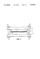
- FIG. 1 is a side schematic view of an apparatus for sintering nickel metal coated graphite fiber mats
- FIG. 2 is an optical photograph of nickel coated graphite particles produced from graphite powder by using with a Ni(CO) 4 decomposition process
- FIG. 3 shows a small plaque cut from a sinter of the nickel coated graphite particles
- FIG. 4 is an optical micrograph of a portion of that small plaque.
- the present invention provides a method of producing a new nickel electrode grid by coating high density graphite fibers in the form of a mat or web with pure (99+ %) nickel metal produced by decomposing nickel carbonyl, Ni(CO) 4 , at elevated temperatures (for example 180° C., as in the Mond process).
- the nickel coated high density graphite fibers are then placed around a current collector and sintered together using heat and pressure to form the electrode grid.
- "High density graphite fibers” refer to fibers having a density of more than 1.80 g/cm 3 , preferably more than 1.90 gm/cm 3 , and more preferably more than 1.95 g/cm 3 .
- the theoretical maximum density for graphite is 2.1 g/cm 3 .
- Thornel graphite fiber
- Type P mat Type P mat
- Grade VMA Standard Carbide technical information bulletin No. 465-225 describes "Thornel” mat grade VMA as "composed of high-strength, high-modulus carbon or graphite filaments in a random-layered orientation. The fine diametered filaments are one to three inches long and are mechanically bonded to form a continuous web of material 0.4 inches thick, 22 inches wide that is supplied in rolls approximately 40 feet long.” The bulletin also lists the following properties for "Thornel" mat grade VMA:
- Carbon or graphite fibers produced by charring or graphiticizing rayon, cellulose, or similar fibers have low densities and therefore are not suitable for this invention.
- Sinter nickel-coated grids made of these fibers swell and disintegrate during cycling of alkaline nickel cells.
- these lower density fibers appear to have larger pores or fissures which are not fully protected by the nickel coating from attack by the KOH electrolyte.
- Nickel carbonyl, Ni(CO) 4 is a colorless, volatile, toxic, flammable, mobile liquid with a characteristic odor. It has a molecular weight of 170.75, a specific gravity of 1.32, a melting point of -25° C., and a boiling point of 43° C.
- the Merck Index 10th ed. states that Ni(CO) 4 "[o]xidizes in air: explodes at 60° C.”
- Ni(CO) 4 is also very toxic having a maximum allowable concentration in air of 0.001 parts per million. For these reasons, extreme care and special equipment is required to confine the Ni(CO) 4 is this process.
- the nickel plating step comprises exposing a heated high density graphite fiber mat to Ni(CO) 4 vapor in a confined space free of air.
- Ni(CO) 4 vapor comes in contact with the heated graphite, the Ni(CO) 4 decomposes depositing nickel metal on the surface of the graphite and releasing carbon monoxide (CO).
- the preferred method of performing the nickel plating step is by using a modified Mond process.
- the conventional mond process is used to refine nickel ores. Van Nostrand's Scientific Encyclopedia, 5th ed., pp 1613-14 states, "...[i]n (2) the Mond process, the nickel oxide is combined with carbon monoxide (CO) to form nickel carbonyl gas, Ni(CO) 4 .
- the impurities, including cobalt, are left as a solid residue.
- the nickel carbonyl is decomposed, the freed nickel condensing on nickel shot and the carbon monoxide recycled.
- carbon monoxide is passed over reduced fine nickel powder at a temperature at which the product Ni(CO) 4 is a gas but below the temperature at which Ni(CO) 4 decomposes.
- the high density graphite fiber mats are heated to a temperature above the decomposition temperature of Ni(CO) 4 and placed into a chamber (free of air) into which the Ni(CO) 4 gas is fed.
- the high density graphite mats are preferably heated to a temperature of from 125° C. to 600° C., more preferably from 160° C. to 500° C., and still more preferably from 180° C. to 350° C.
- the Ni(CO) 4 decomposes, depositing pure (99.9%) nickel metal on the graphite surface and generating carbon monoxide which is preferably recycled to produce more Ni(CO) 4 .
- the nickel coated graphite fiber mats are removed for the sintering step.
- Conventional means such as infrared, resistance, or inductive heating may be used to heat the graphite fiber mats during this Ni(CO) 4 decomposition nickel plating process.
- An electric current may be passed through a graphite mat because graphite is an electrical conductor. The electrical resistance of the graphite generates heat in the mat.
- An inductive furnace may also be used to heat the graphite mat.
- Ni(CO) 4 gas which is not an electrical conductor will not be heated.
- the chamber containing the graphite mat and Ni(CO) 4 gas must be a nonconductor so that it does not heat up. If the chamber inner walls heat up, Ni(CO) 4 gas will decompose on them and deposit nickel metal.
- the nickel coated graphite fiber mats are sintered on to a strong, lightweight current collector. Thin nickel strips will work well as the current collector, referring to the figure, one piece of nickel coated graphite fiber mat 10 is placed on each side of a strong, light weight current collector 12. This sandwich is then placed between two ceramic tile plates 14 which are then placed between two stainless steel plates 16. The stainless steel plates are then compressed (e.g., in a carver hydrolic press) until the sandwich of nickel coated graphite fiber mats 10 and current collector 12 is of the desired thickness. The stainless steel plates 16 are then bolted together to maintain compression on the sandwich during sintering. The compressed nickel coated graphite fiber mats 10 are then sintered at a temperature of preferably from about 775° C.
- the ceramic tiles 14 may be replaced by coating the steel plates 16 with MgO, a parting agent.
- the current collecter may also be attached to a sintered nickel metal coated graphite fiber mat later by other known means such as riveting.
- sintering is the least expensive, most effective method of attaching the nickel coated graphite mats to the current collector.
- a sintered nickel coated dense graphite fiber mat electrode grid produced by this invention may then be impregnated with active materials such as nickel hydroxide, nickel oxide, mixtures of nickel hydroxide and nickel oxide, cadmium hydroxide, cadmium oxide, or mixtures of cadmium hydroxide and cadmium oxide to produce, for example, nickel or cadmium electrodes.
- active materials such as nickel hydroxide, nickel oxide, mixtures of nickel hydroxide and nickel oxide, cadmium hydroxide, cadmium oxide, or mixtures of cadmium hydroxide and cadmium oxide to produce, for example, nickel or cadmium electrodes.
- the nickel coated graphite composite powder used in this example was manufactured by Sherritt-Gordon Mines, limited, Alberta, Canada using Ni(CO) 4 in a Mond process.
- the composite powder was composed of 50 weight percent of pure nickel and 50 weight percent of graphite.
- FIG. 2 is an optical photograph of particles of the composite powder. The particles are of typically random circular shape. The nickel coating is evident on particles with proper angle to the light source. A portion of this nickel coated graphite powder was spread on a stainless steel plate dagged with MgO as a release agent. A second steel plate (with MgO coating) was compressed onto the nickel coated graphite powder and the steel plates were bolted together to maintain the compression.
- FIG. 3 shows a small plaque cut from the sinter.
- FIG. 4 shows an optical micrograph of a portion of the plaque. Sintering has occurred and the plaque could be impregnated with active material, although the relatively large particle size produced a less than ideal porous structure.
- nickel coated graphite materials such as powders or fibers can be sintered together.
Abstract
A process for producing a lightweight electrode grid by exposing a heated t of dense graphite fibers to Ni(CO)4 gas wherein the Ni(CO)4 decomposes upon contact with the graphite fibers depositing nickel metal coating on the graphic fibers. The nickel coated graphite fibers are then sintered to form the grid. Nickel or cadmium electrodes are made by attaching a current collector to the grid and impregnating the grid with the appropriate nickel or cadmium active material.
Description
This invention relates to electrochemical cells and more particularly to sintered nickel plates for electrochemical cells.
In the nickel-cadmium alkaline cell, porous nickel plates are used to construct both the positive and negative electrodes. The active material for the positive and negative electrodes is contained within the nickel plates. The positive plate contains nickel hydroxide while the negative plate contains cadmium hydroxide. The most efficient structural construction is the sintered nickel plate. This plate is designed for a high surface area to plate volume ratio. To form the plates, fine nickel powder (carbonyl nickel) on a wire screen is placed in a mold and sintered at elevated temperatures (700° -1000° C.) in a reducing atmosphere. The result is a plate (plaque) about 0.030-0.060 inches thick and 70-85% void (porosity).
Sintered nickel plates are lighter and have grater effective areas than do solid nickel plates. However, sintered nickel plates are limited by several factors to certain minimum weights. For example, very high porosities produce a structurally weak plaque which cannot endure the electrical stresses involved in impregnation and cycling. On the other hand if large cavities (pockets) are designed into the plate to hold significant amounts of active material, the problem becomes one of maintaining sufficient electrical conductivity.
In U.S. Pat. No. 3,476,604 titled "Method of Making an Electrode Grid," issued to Peter Faber on Nov. 4, 1969, an electrode grid is formed by sintering a web of nickel-boron coated carbonaceous fibers. In that method, a fabric or felt of cellulose fibers was first charred to produce a web of carbonaceous filaments. These carbonaceous filaments were than at least partially graphiticized. Next, an aqueous solution of a nickel salt in the presence of a reducing boron compound was used to deposit a nickel-boron coating on the carbonaceous filaments. Finally, the web of nickel-boron coated carbonaceous filaments was sintered to form the nickel electrode grid. There are several disadvantages to this approach. First, if carbon or graphite fibers formed by charring materials such as rayon or cellulose fibers are used to produce the sintered nickel electrode grids, the grids swell upon cycling in an alkaline (e.g., KOH) electrolyte. Additionally, carbon or graphite fibers formed in this manner are expensive. Finally, the high purity reducing boron compounds required in the Faber process are very expensive.
In U.S. Pat. No. 4,215,190, titled "Lightweight Battery Electrode," issued to William A. Ferrando and Raymond A. Sutulla on Jul. 29, 1980, an electrode grid is formed by sintering a web of nickel-phosphorous coated graphite fibers having a graphite density of 1.8 g/cm3 or more. The process is cheaper than Faber's process and the dense graphite fibers more resistant to swelling in alkaline electrolytes. Nevertheless, it would be desirable to reduce the cost of producing the nickel grid further. Further, although the phosphorous does not interfer with the electrochemical performance of the nickel, it still acts a diluent, reducing the available nickel surface by as much as 15 percent.
It would be desirable to produce a nickel grid that would possess the lightweight and durableness of the Ferrando et al. grid but which would be cheaper to produce and would have a pure nickel surface available.
Accordingly, an object of this invention is to provide a more economical method of producing strong, lightweight nickel grids for battery electrodes.
Another object of this invention is to provide a method of producing strong, lightweight nickel grids having nickel surfaces that are nearly 100 percent nickel.
A further object of this invention is to provide new low cost, strong, lightweight nickel grids for batteries.
These and other objects of this invention are accomplished by providing
a process for producing a lightweight electrode grid by
A. heating a mat of dense graphite fibers to a temperature at which Ni(CO)4 decomposes;
B. exposing the heated mat of graphite fibers to Ni(CO)4 gas which is at a temperature above the vaporization temperature of Ni(CO)4 but below the decomposition temperature of Ni(CO)4,
wherein the Ni(CO)4 decomposes when it contacts the heated graphite fibers and deposits nickel metal on the graphite fiber surfaces;
C. removing the heated graphite fiber mat from the Ni(CO)4 gas when the desired thickness of nickel metal coating has been produced on the graphite fiber mat; and
D. sintering the nickel coated graphite fiber mat in a reducing atmosphere under heat and pressure to compress the mat to a desired thickness and to fuse the nickel metal coated graphite fibers together.
The grid that is produce can be used to produce an electrode by attaching a current collector to the grid and then impregnating the grid with a nickel active material or a cadmium active material to produce a nickel or a cadmium electrode.
A more complete understanding of the invention and many of the attendant advantages thereto will be readily appreciated as the same becomes better understood by reference to the following detailed description when considered in connection with the accompanying drawings wherein:
FIG. 1 is a side schematic view of an apparatus for sintering nickel metal coated graphite fiber mats;
FIG. 2 is an optical photograph of nickel coated graphite particles produced from graphite powder by using with a Ni(CO)4 decomposition process;
FIG. 3 shows a small plaque cut from a sinter of the nickel coated graphite particles; and
FIG. 4 is an optical micrograph of a portion of that small plaque.
The present invention provides a method of producing a new nickel electrode grid by coating high density graphite fibers in the form of a mat or web with pure (99+ %) nickel metal produced by decomposing nickel carbonyl, Ni(CO)4, at elevated temperatures (for example 180° C., as in the Mond process). The nickel coated high density graphite fibers are then placed around a current collector and sintered together using heat and pressure to form the electrode grid. "High density graphite fibers" refer to fibers having a density of more than 1.80 g/cm3, preferably more than 1.90 gm/cm3, and more preferably more than 1.95 g/cm3. The theoretical maximum density for graphite is 2.1 g/cm3.
An example of a suitable graphite fiber is available from the Union Carbide Corporation, Carbon Products Division under the trade name "Thornel", Type P mat, Grade VMA. Union Carbide technical information bulletin No. 465-225 describes "Thornel" mat grade VMA as "composed of high-strength, high-modulus carbon or graphite filaments in a random-layered orientation. The fine diametered filaments are one to three inches long and are mechanically bonded to form a continuous web of material 0.4 inches thick, 22 inches wide that is supplied in rolls approximately 40 feet long." The bulletin also lists the following properties for "Thornel" mat grade VMA:
              TABLE 1
______________________________________
TYPICAL PROPERTIES AND CHARACTERISTICS
OF "THORNEL" MAT GRADE VMA
                      U.S. CUSTOMARY
PROPERTY              UNITS-VALUE
______________________________________
Filaments
Tensile Strength lb/in.sup.2
                      200,000
Tensile Modulus × 10.sup.6 lb/in.sup.3
                      35
Density lb/in.sup.3   .072
Electrical Resistivity 10.sup.4 ohm-cm
                      12
Diameter μ         9
Surface Area m.sup.2 /g
                      0.4
Carbon Assay %        98
pH -                  6
Mat
Areal density lb/ft.sup.2
                      0.07
Bulk Density lb/ft.sup.3
                      2.25
Tensile Strength (long) lb/in width
                      0.8
Tensile Strength (trans.) lb/in width
                      0.8
Electrical Resistivity (trans.) 10.sup.4 ohm-cm
                      7000
Thermal Conductivity Thickness BTU
                      0.24
in/h/ft.sup.2 °F.
______________________________________
William E. Chambers in an article entitled "Low-cost High-performance Carbon Fibers," Mechanical Engineering, December 1975, pp. 38-39 describes the process for making the "Thornel" Type P (pitch) carbon fibers. The dimensions of the fibers are not a critical feature of this invention, but rather are chosen for certain practical reasons. For example, the smaller the diameter of the fiber, the larger the effective area of the sintered nickel grid will be. Thus, it is contemplated that fibers with diameter less that the 9 microns may be used. On the other hand, short fibers will produce sintered nickel grids that require support screens and thus added weight. Tests have demonstrated that longer fibers (e.g., one to three inches) produce sintered nickel grids which do not require support screens.
Carbon or graphite fibers produced by charring or graphiticizing rayon, cellulose, or similar fibers have low densities and therefore are not suitable for this invention. Sinter nickel-coated grids made of these fibers swell and disintegrate during cycling of alkaline nickel cells. Unlike the dense graphite or carbon fibers used in the present invention, these lower density fibers appear to have larger pores or fissures which are not fully protected by the nickel coating from attack by the KOH electrolyte.
Nickel carbonyl, Ni(CO)4, is a colorless, volatile, toxic, flammable, mobile liquid with a characteristic odor. It has a molecular weight of 170.75, a specific gravity of 1.32, a melting point of -25° C., and a boiling point of 43° C. The Merck Index 10th ed. , states that Ni(CO)4 "[o]xidizes in air: explodes at 60° C." Ni(CO)4 is also very toxic having a maximum allowable concentration in air of 0.001 parts per million. For these reasons, extreme care and special equipment is required to confine the Ni(CO)4 is this process.
The nickel plating step comprises exposing a heated high density graphite fiber mat to Ni(CO)4 vapor in a confined space free of air. When the Ni(CO)4 vapor comes in contact with the heated graphite, the Ni(CO)4 decomposes depositing nickel metal on the surface of the graphite and releasing carbon monoxide (CO).
The preferred method of performing the nickel plating step is by using a modified Mond process. The conventional mond process is used to refine nickel ores. Van Nostrand's Scientific Encyclopedia, 5th ed., pp 1613-14 states, "...[i]n (2) the Mond process, the nickel oxide is combined with carbon monoxide (CO) to form nickel carbonyl gas, Ni(CO)4. The impurities, including cobalt, are left as a solid residue. Upon further heating of the gas to about 180° C., the nickel carbonyl is decomposed, the freed nickel condensing on nickel shot and the carbon monoxide recycled. The Mond process also makes a nickel of 99.9% purity." Van Nostrand's, supra, page 1615, also states that "Ni(CO)4 is prepared by reaction of carbon monoxide with freshly reduced nickel, which occurs at ordinary temperatures and pressures." The Merck Index, 10th ed., Monograph number 6342. Nickel Carbonyl, states "made by passing carbon monoxide over finely divided nickel: Mond et al. J. Chem Soc, 57, 749 (1890); Gilliland, Blanchard,Inorq. Syn. 2, 234 (1946)...." In the modified process used in this invention, carbon monoxide is passed over reduced fine nickel powder at a temperature at which the product Ni(CO)4 is a gas but below the temperature at which Ni(CO)4 decomposes. The high density graphite fiber mats are heated to a temperature above the decomposition temperature of Ni(CO)4 and placed into a chamber (free of air) into which the Ni(CO)4 gas is fed. The high density graphite mats are preferably heated to a temperature of from 125° C. to 600° C., more preferably from 160° C. to 500° C., and still more preferably from 180° C. to 350° C. Upon contacting the heated dense graphite fiber mat, the Ni(CO)4 decomposes, depositing pure (99.9%) nickel metal on the graphite surface and generating carbon monoxide which is preferably recycled to produce more Ni(CO)4. When the desired thickness of nickel coating is achieved, the nickel coated graphite fiber mats are removed for the sintering step. Conventional means such as infrared, resistance, or inductive heating may be used to heat the graphite fiber mats during this Ni(CO)4 decomposition nickel plating process. An electric current may be passed through a graphite mat because graphite is an electrical conductor. The electrical resistance of the graphite generates heat in the mat. An inductive furnace may also be used to heat the graphite mat. The Ni(CO)4 gas which is not an electrical conductor will not be heated. The chamber containing the graphite mat and Ni(CO)4 gas must be a nonconductor so that it does not heat up. If the chamber inner walls heat up, Ni(CO)4 gas will decompose on them and deposit nickel metal.
To produce an electrode grid structure the nickel coated graphite fiber mats are sintered on to a strong, lightweight current collector. Thin nickel strips will work well as the current collector, referring to the figure, one piece of nickel coated graphite fiber mat 10 is placed on each side of a strong, light weight current collector 12. This sandwich is then placed between two ceramic tile plates 14 which are then placed between two stainless steel plates 16. The stainless steel plates are then compressed (e.g., in a carver hydrolic press) until the sandwich of nickel coated graphite fiber mats 10 and current collector 12 is of the desired thickness. The stainless steel plates 16 are then bolted together to maintain compression on the sandwich during sintering. The compressed nickel coated graphite fiber mats 10 are then sintered at a temperature of preferably from about 775° C. to 975° C., more preferably from 800° C. to 950° C., and still more preferably from 810° C. to 900° C. in a hydrogen (reducing) atmosphere. The ceramic tiles 14 may be replaced by coating the steel plates 16 with MgO, a parting agent. The current collecter may also be attached to a sintered nickel metal coated graphite fiber mat later by other known means such as riveting. However, sintering is the least expensive, most effective method of attaching the nickel coated graphite mats to the current collector.
A sintered nickel coated dense graphite fiber mat electrode grid produced by this invention may then be impregnated with active materials such as nickel hydroxide, nickel oxide, mixtures of nickel hydroxide and nickel oxide, cadmium hydroxide, cadmium oxide, or mixtures of cadmium hydroxide and cadmium oxide to produce, for example, nickel or cadmium electrodes. William A. Ferrando and Raymond A. Sutula in U.S. Pat. No. 4,215,190, herein incorporated in its entirety, at Example 3, columns 5-6, disclose a typical method of impregnating active material which will work for the grids of the present invention.
The general nature of the invention having been set forth, the following examples are presented as specific illustrations thereof. It will be understood that this invention is not limited to these specific examples, but is susceptible to various modifications that will be recognized by one of ordinary skill in the art.
The nickel coated graphite composite powder used in this example was manufactured by Sherritt-Gordon Mines, limited, Alberta, Canada using Ni(CO)4 in a Mond process. The composite powder was composed of 50 weight percent of pure nickel and 50 weight percent of graphite. FIG. 2 is an optical photograph of particles of the composite powder. The particles are of typically random circular shape. The nickel coating is evident on particles with proper angle to the light source. A portion of this nickel coated graphite powder was spread on a stainless steel plate dagged with MgO as a release agent. A second steel plate (with MgO coating) was compressed onto the nickel coated graphite powder and the steel plates were bolted together to maintain the compression. The compressed sandwich of steel plates and nickel coated graphite powder was placed in an air tight Inconel sleeve and sintered for 2 hours at 810° C. in pure H2 atmosphere. Sintering of the composite powder was achieved. FIG. 3 shows a small plaque cut from the sinter. FIG. 4 shows an optical micrograph of a portion of the plaque. Sintering has occurred and the plaque could be impregnated with active material, although the relatively large particle size produced a less than ideal porous structure.
This example, demonstrates that nickel coated graphite materials such as powders or fibers can be sintered together.
As will be evident to those skilled in the art, various modifications can be made, or followed, in light of the foregoing disclosure and discussion, without departing from the spirit or the scope of the disclosure or the scope of the claims.
Claims (11)
1. A process for producing a lightweight electrode grid comprising:
A. heating a mat of dense graphite fibers to a temperature at which Ni(CO)4 decomposes;
B. exposing the heated mat of graphite fibers to Ni(CO)4 gas which is at a temperature above the vaporization temperature of Ni(CO)4 but below the decomposition temperature of Ni(CO)4,
wherein the Ni(CO)4 decomposes when it contacts the heated graphite fibers and deposits nickel metal on the graphite fiber surfaces;
C. removing the heated graphite fiber mat from the Ni(CO)4 gas when the desired thickness of nickel metal coating has been produced on the graphite fiber mat; and
D. sintering the nickel coated graphite fiber mat in a reducing atmosphere under heat and pressure to compress the mat to a desired thickness and to fuse the nickel metal coated graphite fibers together.
2. The process of claim 1 wherein in the sinter process of step D the nickel coated graphite fiber mat is attached to a current collector.
3. The process of claim 1 wherein the mat of dense graphite fibers is heated in step A to a temperature of from 125° C. to 600° C.
4. The process of claim 3 wherein the mat of dense graphite fibers is heated in step A to a temperature of from 160° C. to 500° C.
5. The process of claim 4 wherein the mat of dense graphite fibers is heated in step A to a temperature of from 180° C. to 350° C.
6. The process of claim 1 wherein heating means are used in step B to maintain the temperature of the mat of graphite fibers.
7. The process of claim 1 wherein the carbon monoxide generated by the decomposition of Ni(CO)4 in step B is taken and reacted with fine nickel metal powder to produce more Ni(CO)4 gas for use in step B.
8. The process of claim 1 wherein the reducing atmosphere used in step D is pure hydrogen gas.
9. The process of claim 1 wherein the sintering temperature in step D is from about 775° C. to about 975° C.
10. The process of claim 9 wherein the sintering temperature in step D is from 800° C. to 950° C.
11. The process of claim 10 wherein the sintering temperature in step D is from 810° C. to 900° C.
Priority Applications (2)
| Application Number | Priority Date | Filing Date | Title |
|---|---|---|---|
| US07/728,915 US5197993A (en) | 1991-07-11 | 1991-07-11 | Lightweight battery electrode and method of making it |
| US08/087,002 US5362580A (en) | 1991-07-11 | 1993-07-07 | Lightweight battery electrode and method of making it |
Applications Claiming Priority (1)
| Application Number | Priority Date | Filing Date | Title |
|---|---|---|---|
| US07/728,915 US5197993A (en) | 1991-07-11 | 1991-07-11 | Lightweight battery electrode and method of making it |
Related Child Applications (1)
| Application Number | Title | Priority Date | Filing Date |
|---|---|---|---|
| US97796692A Division | 1991-07-11 | 1992-11-18 |
Publications (1)
| Publication Number | Publication Date |
|---|---|
| US5197993A true US5197993A (en) | 1993-03-30 |
Family
ID=24928788
Family Applications (2)
| Application Number | Title | Priority Date | Filing Date |
|---|---|---|---|
| US07/728,915 Expired - Fee Related US5197993A (en) | 1991-07-11 | 1991-07-11 | Lightweight battery electrode and method of making it |
| US08/087,002 Expired - Fee Related US5362580A (en) | 1991-07-11 | 1993-07-07 | Lightweight battery electrode and method of making it |
Family Applications After (1)
| Application Number | Title | Priority Date | Filing Date |
|---|---|---|---|
| US08/087,002 Expired - Fee Related US5362580A (en) | 1991-07-11 | 1993-07-07 | Lightweight battery electrode and method of making it |
Country Status (1)
| Country | Link |
|---|---|
| US (2) | US5197993A (en) |
Cited By (10)
| Publication number | Priority date | Publication date | Assignee | Title |
|---|---|---|---|---|
| US5362580A (en) * | 1991-07-11 | 1994-11-08 | The United States Of America As Represented By The Secretary Of The Navy | Lightweight battery electrode and method of making it |
| US5423110A (en) * | 1991-09-17 | 1995-06-13 | Hydro-Quebec | Process for the preparation of collectors-electrodes for the thin film cell, collectors-electrodes assemblies and cells obtained |
| US5468570A (en) * | 1995-01-26 | 1995-11-21 | The United States Of America As Represented By The Secretary Of The Navy | Lightweight zinc electrode |
| US5478364A (en) * | 1993-05-14 | 1995-12-26 | Sharp Kabushiki Kaisha | Method of manufacturing lithium secondary battery |
| US5700363A (en) * | 1996-02-15 | 1997-12-23 | Inco Limited | Porous nickel electrode substrate |
| EP0921210A1 (en) * | 1997-12-01 | 1999-06-09 | Inco Limited | Method of preparing porous nickel-aluminium structures |
| EP1587603A2 (en) * | 2003-01-28 | 2005-10-26 | Fluor Corporation | Improved configuration and process for carbonyl removal |
| US8017273B2 (en) | 2008-04-28 | 2011-09-13 | Ut-Battelle Llc | Lightweight, durable lead-acid batteries |
| CN104037423A (en) * | 2014-06-19 | 2014-09-10 | 合肥国轩高科动力能源股份公司 | Preparation method of porous nickle current collector of lithium ion battery |
| US10454114B2 (en) | 2016-12-22 | 2019-10-22 | The Research Foundation For The State University Of New York | Method of producing stable, active and mass-producible Pt3Ni catalysts through preferential co etching |
Families Citing this family (6)
| Publication number | Priority date | Publication date | Assignee | Title |
|---|---|---|---|---|
| US5601892A (en) * | 1995-07-19 | 1997-02-11 | Abu Ab | Hollow rods with nickel coated graphite fibers |
| US6463992B1 (en) | 2000-03-22 | 2002-10-15 | Pratt & Whitney Canada Corp. | Method of manufacturing seamless self-supporting aerodynamically contoured sheet metal aircraft engine parts using nickel vapor deposition |
| TWI286349B (en) * | 2000-10-02 | 2007-09-01 | Ibm | Electrode, fabricating method thereof, and organic electroluminescent device |
| US7206189B2 (en) * | 2002-12-20 | 2007-04-17 | Advanced Energy Technology Inc. | Composite electrode and current collectors and processes for making the same |
| US20090029196A1 (en) * | 2007-07-27 | 2009-01-29 | More Energy Ltd. | Dry method of making a gas diffusion electrode |
| US20110143262A1 (en) * | 2009-12-10 | 2011-06-16 | Gm Global Technology Operations, Inc. | Gas diffusion media made from electrically conductive coatings on non-conductive fibers |
Citations (5)
| Publication number | Priority date | Publication date | Assignee | Title |
|---|---|---|---|---|
| US1081531A (en) * | 1910-04-11 | 1913-12-16 | Harry C Hubbell | Method of making storage-battery electrodes. |
| US4215190A (en) * | 1979-06-08 | 1980-07-29 | Ferrando William A | Lightweight battery electrode |
| US4476206A (en) * | 1982-02-01 | 1984-10-09 | Compagnie Europeene D'accumulateurs | Fiber reinforced grid for a storage cell, and method of manufacturing it |
| US4861690A (en) * | 1988-06-06 | 1989-08-29 | Ope Henry F | Lightweight battery construction |
| US5080963A (en) * | 1989-05-24 | 1992-01-14 | Auburn University | Mixed fiber composite structures high surface area-high conductivity mixtures |
Family Cites Families (3)
| Publication number | Priority date | Publication date | Assignee | Title |
|---|---|---|---|---|
| JPS589822B2 (en) * | 1976-11-26 | 1983-02-23 | 東邦ベスロン株式会社 | Carbon fiber reinforced metal composite prepreg |
| US4648902A (en) * | 1983-09-12 | 1987-03-10 | American Cyanamid Company | Reinforced metal substrate |
| US5197993A (en) * | 1991-07-11 | 1993-03-30 | The United States Of America As Represented By The Secretary Of The Navy | Lightweight battery electrode and method of making it |
-
1991
- 1991-07-11 US US07/728,915 patent/US5197993A/en not_active Expired - Fee Related
-
1993
- 1993-07-07 US US08/087,002 patent/US5362580A/en not_active Expired - Fee Related
Patent Citations (5)
| Publication number | Priority date | Publication date | Assignee | Title |
|---|---|---|---|---|
| US1081531A (en) * | 1910-04-11 | 1913-12-16 | Harry C Hubbell | Method of making storage-battery electrodes. |
| US4215190A (en) * | 1979-06-08 | 1980-07-29 | Ferrando William A | Lightweight battery electrode |
| US4476206A (en) * | 1982-02-01 | 1984-10-09 | Compagnie Europeene D'accumulateurs | Fiber reinforced grid for a storage cell, and method of manufacturing it |
| US4861690A (en) * | 1988-06-06 | 1989-08-29 | Ope Henry F | Lightweight battery construction |
| US5080963A (en) * | 1989-05-24 | 1992-01-14 | Auburn University | Mixed fiber composite structures high surface area-high conductivity mixtures |
Cited By (15)
| Publication number | Priority date | Publication date | Assignee | Title |
|---|---|---|---|---|
| US5362580A (en) * | 1991-07-11 | 1994-11-08 | The United States Of America As Represented By The Secretary Of The Navy | Lightweight battery electrode and method of making it |
| US5423110A (en) * | 1991-09-17 | 1995-06-13 | Hydro-Quebec | Process for the preparation of collectors-electrodes for the thin film cell, collectors-electrodes assemblies and cells obtained |
| US5478364A (en) * | 1993-05-14 | 1995-12-26 | Sharp Kabushiki Kaisha | Method of manufacturing lithium secondary battery |
| US5468570A (en) * | 1995-01-26 | 1995-11-21 | The United States Of America As Represented By The Secretary Of The Navy | Lightweight zinc electrode |
| US5700363A (en) * | 1996-02-15 | 1997-12-23 | Inco Limited | Porous nickel electrode substrate |
| EP0921210A1 (en) * | 1997-12-01 | 1999-06-09 | Inco Limited | Method of preparing porous nickel-aluminium structures |
| EP1587603A2 (en) * | 2003-01-28 | 2005-10-26 | Fluor Corporation | Improved configuration and process for carbonyl removal |
| EP1587603A4 (en) * | 2003-01-28 | 2007-04-25 | Fluor Corp | Improved configuration and process for carbonyl removal |
| US20080102009A1 (en) * | 2003-01-28 | 2008-05-01 | Ravi Ravikumar | Configuration and process for carbonyl removal |
| US7597743B2 (en) * | 2003-01-28 | 2009-10-06 | Fluor Technologies Corporation | Configuration and process for carbonyl removal |
| US8017273B2 (en) | 2008-04-28 | 2011-09-13 | Ut-Battelle Llc | Lightweight, durable lead-acid batteries |
| US8445138B2 (en) | 2008-04-28 | 2013-05-21 | Ut-Battelle Llc | Lightweight, durable lead-acid batteries |
| CN104037423A (en) * | 2014-06-19 | 2014-09-10 | 合肥国轩高科动力能源股份公司 | Preparation method of porous nickle current collector of lithium ion battery |
| CN104037423B (en) * | 2014-06-19 | 2016-07-13 | 合肥国轩高科动力能源有限公司 | The preparation method of lithium ion battery nickel porous collector |
| US10454114B2 (en) | 2016-12-22 | 2019-10-22 | The Research Foundation For The State University Of New York | Method of producing stable, active and mass-producible Pt3Ni catalysts through preferential co etching |
Also Published As
| Publication number | Publication date |
|---|---|
| US5362580A (en) | 1994-11-08 |
Similar Documents
| Publication | Publication Date | Title |
|---|---|---|
| US5197993A (en) | Lightweight battery electrode and method of making it | |
| US5080963A (en) | Mixed fiber composite structures high surface area-high conductivity mixtures | |
| EP0473715B1 (en) | Mixed fiber composite structures: method of preparation, articles therefrom, and uses therefor | |
| US6103373A (en) | Carbon fiber material and electrode materials and method of manufacture therefor | |
| US4215190A (en) | Lightweight battery electrode | |
| KR100261258B1 (en) | Battery electrode substrate and process for producing the same | |
| US6528211B1 (en) | Carbon fiber material and electrode materials for batteries | |
| US3266936A (en) | Electrode supports and method for their production | |
| US20060166075A1 (en) | Flame-resistant acrylic fiber nonwoven fabric, carbon fiber nonwoven fabric, and method for production thereof | |
| WO1990004859A1 (en) | Fabrication of dual porosity electrode structure | |
| AU683396B2 (en) | Method of making a battery plate | |
| US3657014A (en) | Porous electrode-support for alkaline accumulators | |
| WO1996041745A1 (en) | High bulk density, parallel carbon fibers | |
| US3689320A (en) | Method for making a battery plate using cellulosic material | |
| US3476604A (en) | Method of making an electrode grid | |
| US6245455B1 (en) | Sodium-sulfur secondary battery | |
| JP2992396B2 (en) | Carbon fiber felt and method for producing the same | |
| Vohler et al. | New forms of carbon | |
| JP3468493B2 (en) | Battery electrode substrate and method of manufacturing the same | |
| JP3181768B2 (en) | Electrode substrate and method for producing the same | |
| US3711336A (en) | Ceramic separator and filter and method of production | |
| JPH08138651A (en) | Carbonaceous electrode plate for non-aqueous electrolyte secondary battery and secondary battery | |
| WO1998021767A2 (en) | Metal foam support member for secondary battery electrode | |
| Fedorchenko | Progress in work in the field of high-porosity materials from metal powders and fibers | |
| JP4464049B2 (en) | Gas diffusion electrode substrate precursor, gas diffusion electrode substrate, gas diffusion electrode, and fuel cell |
Legal Events
| Date | Code | Title | Description |
|---|---|---|---|
| AS | Assignment |
Owner name: UNITED STATES OF AMERICA, THE, AS REPRESENTED BY T Free format text: ASSIGNMENT OF ASSIGNORS INTEREST.;ASSIGNORS:FERRANDO, WILLIAM A.;DIVECHA, AMARNATH P.;REEL/FRAME:005777/0810;SIGNING DATES FROM 19910705 TO 19910708 |
|
| FPAY | Fee payment |
Year of fee payment: 4 |
|
| REMI | Maintenance fee reminder mailed | ||
| LAPS | Lapse for failure to pay maintenance fees | ||
| FP | Lapsed due to failure to pay maintenance fee |
Effective date: 20010330 |
|
| STCH | Information on status: patent discontinuation |
Free format text: PATENT EXPIRED DUE TO NONPAYMENT OF MAINTENANCE FEES UNDER 37 CFR 1.362 |