US5197245A - Structural wall reinforcement apparatus and method - Google Patents
Structural wall reinforcement apparatus and method Download PDFInfo
- Publication number
- US5197245A US5197245A US07/566,612 US56661290A US5197245A US 5197245 A US5197245 A US 5197245A US 56661290 A US56661290 A US 56661290A US 5197245 A US5197245 A US 5197245A
- Authority
- US
- United States
- Prior art keywords
- wall
- anchor plate
- block
- concrete
- cable assemblies
- Prior art date
- Legal status (The legal status is an assumption and is not a legal conclusion. Google has not performed a legal analysis and makes no representation as to the accuracy of the status listed.)
- Expired - Fee Related
Links
- 238000000034 method Methods 0.000 title claims abstract description 11
- 230000002787 reinforcement Effects 0.000 title claims abstract description 4
- 230000000712 assembly Effects 0.000 claims abstract description 25
- 238000000429 assembly Methods 0.000 claims abstract description 25
- 230000003014 reinforcing effect Effects 0.000 claims abstract description 23
- 239000000463 material Substances 0.000 claims abstract description 15
- 210000002435 tendon Anatomy 0.000 claims description 19
- 239000011449 brick Substances 0.000 claims description 8
- 238000004873 anchoring Methods 0.000 claims 6
- 239000011440 grout Substances 0.000 description 4
- 239000004593 Epoxy Substances 0.000 description 3
- 239000004567 concrete Substances 0.000 description 3
- 239000011378 shotcrete Substances 0.000 description 3
- 229910000831 Steel Inorganic materials 0.000 description 2
- 239000000853 adhesive Substances 0.000 description 2
- 230000001070 adhesive effect Effects 0.000 description 2
- 238000010276 construction Methods 0.000 description 2
- 230000006378 damage Effects 0.000 description 2
- 239000010959 steel Substances 0.000 description 2
- 239000007767 bonding agent Substances 0.000 description 1
- 239000002131 composite material Substances 0.000 description 1
- 230000006835 compression Effects 0.000 description 1
- 238000007906 compression Methods 0.000 description 1
- 230000007797 corrosion Effects 0.000 description 1
- 238000005260 corrosion Methods 0.000 description 1
- 230000008878 coupling Effects 0.000 description 1
- 238000010168 coupling process Methods 0.000 description 1
- 238000005859 coupling reaction Methods 0.000 description 1
- 230000000694 effects Effects 0.000 description 1
- 238000009434 installation Methods 0.000 description 1
- 238000012986 modification Methods 0.000 description 1
- 230000004048 modification Effects 0.000 description 1
Images


Classifications
-
- E—FIXED CONSTRUCTIONS
- E04—BUILDING
- E04G—SCAFFOLDING; FORMS; SHUTTERING; BUILDING IMPLEMENTS OR AIDS, OR THEIR USE; HANDLING BUILDING MATERIALS ON THE SITE; REPAIRING, BREAKING-UP OR OTHER WORK ON EXISTING BUILDINGS
- E04G23/00—Working measures on existing buildings
- E04G23/02—Repairing, e.g. filling cracks; Restoring; Altering; Enlarging
- E04G23/0218—Increasing or restoring the load-bearing capacity of building construction elements
Definitions
- the present invention relates to structural wall reinforcing apparatus and methods in general and in particular to an apparatus and method for reinforcing brick and block walls.
- principal objects of the present invention are a method and apparatus for reinforcing a brick and/or block wall structure.
- a plurality of post-tensioned cable assemblies which are located at selected positions along and attached to the.
- Each of the cable assemblies is anchored at the base and to the top of the wall and comprises a tendon which runs through a cable duct or grout tube.
- reinforcing wire mesh is laid across the assemblies and anchored to the wall at selected points by steel dowels embedded in the wall.
- the cable assemblies and wire mesh are then embedded in a layer of Gunnite or Shotcrete which attaches to the wall by itself or is attached to the wall as by a bonding agent or doweling.
- the tendons are tensioned and the cable ducts filled with grout. The tensioning of the tendons results in compressive forces being transferred to the wall in such a manner that the resulting composite wall structure is as strong as or stronger than walls constructed originally using current building techniques.
- FIG. 1 is a front elevation view of a brick wall reinforced with cable assemblies according to the present invention
- FIG. 2 is a side elevation view of a section of the wall of FIG. 1;
- FIG. 3 is a side elevation view showing the installation of an upper anchor plate and wire mesh according to the present invention.
- FIG. 4 is a front elevation view of FIG. 3 with the wire mesh omitted for clarity;
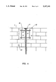
- FIG. 5 is a side elevation view of a lower anchor plate, i.e. footing anchor, showing the manner in which the lower anchor plate of the cable assemblies are anchored to a wall foundation using footing anchor dowels according to the present invention
- FIG. 6 is a top plan view of FIG. 5;
- FIG. 7 is an alternative view of the footing anchor comprising a spiral rebar cage tied to the footing anchor dowels according to the present invention.
- FIG. 1 there is shown an elevation view of an unreinforced brick wall designated generally as 1 which is built on a foundation 2. Attached at selected locations across the face of the wall 1 there is provided a plurality of cable assemblies 3.
- each of the cable assemblies 3 an upper anchor plate 5 and a lower anchor plate 6.
- a cable duct 7, also called a grout tube comprising an upper duct section 8 and a lower duct section 9 which are joined by a coupling 10.
- the duct 7 is provided for enclosing a tendon 11, as shown in FIGS. 5 and 6.
- the upper end of the tendon 11 is anchored in the anchor plate 5 and the lower end of the tendon 11 is anchored in the anchor plate 6 by means of clamping wedges (not shown).
- the clamping wedges grasp the tendon in a well known manner so as to maintain the tendon under tension, as will be further described below.
- the upper anchor plate 5 and the upper section 8 of the cable duct 7 are embedded in a square block of concrete 15.
- a plurality of reinforcing bars 16, which are joined at their intersecting points, are also embedded in the concrete block 15, as shown more clearly in FIG. 4.
- the block 15 is rigidly attached to at least a portion of the top of the wall 1 so as to impart compressive forces thereto, as will be further described below.
- the lower anchor plate 6 is mounted on the foundation 2 which extends beneath the wall 1. If a foundation similar to foundation 2 does not exist in the original construction of the wall 1, a foundation 2 is poured and a rigid connection made in any suitable manner with the original foundation.
- Reinforcing bar segments 17 and 18 comprise a lower section 19 and an upper horizontal section 20.
- the lower sections 19 are embedded in the foundation 2 and rigidly affixed thereto by means of an adhesive epoxy, or the like.
- the segments 17 and 18 are arranged to extend over the anchor plate 6 so as to capture the anchor plate 6 between the segments 17 and 18 and the foundation 2.
- wire mesh 21 is placed across the face of the wall 1 and attached thereto as by a plurality of dowels 22 which are rigidly attached, as by epoxy or the like, in holes provided therefor in the wall 1.
- the adjacent surface of the wall 1 is sandblasted and coated with an adhesive, such as an epoxy.
- an adhesive such as an epoxy.
- a concrete-like material typically known under the trade name Gunnite or Shotcrete, is applied over the wall between the lower surface of the concrete block 15 and the upper surface of the foundation 2 for embedding the exposed portion of the cable assemblies 3 and the wire mesh 21.
- Gunnite or the like has substantially the same or greater compressive strength as does the brick typically used in the wall 1.
- a jack 25 is coupled to the upper end of the tendon 11 for applying tensile force to the tendon 11.
- tensile force e.g. 6,000 pounds
- a relaxation of the tensile force will cause the wedge-shaped clamping members in the upper anchor plate 5 to grasp the upper end of the tendon 11, maintaining the tendon 11 under tension.
- This tension is then transmitted via the block 15 to the wall 1, placing the wall 1 under compression.
- a spiral rebar cage designated generally as 30.
- Cage 30 is placed around the footing anchor rebar 17 and 18 and tied thereto in a conventional manner before being embedded in the Gunnite 26.
- the dowels 21, the rebar sections 16, 17 and 18, typically comprise No. 4 or No. 5 rebar.
- the layer of Gunnite 26 is typically 4-6 inches thick and the block 15 is typically an 8-10 inch square block. After the tendon is tensioned, grout is forced into the duct 7 in a conventional manner so as to protect the tendon 11 from corrosion.
Landscapes
- Engineering & Computer Science (AREA)
- Architecture (AREA)
- Chemical & Material Sciences (AREA)
- Chemical Kinetics & Catalysis (AREA)
- Electrochemistry (AREA)
- Mechanical Engineering (AREA)
- Civil Engineering (AREA)
- Structural Engineering (AREA)
- Reinforcement Elements For Buildings (AREA)
Abstract
Structural wall reinforcement method and apparatus for reinforcing a wall comprising a plurality of post-tensioned cable assemblies and wire mesh embedded in a layer of concrete-like material for applying compressive forces to the wall.
Description
1. Field of the Invention
The present invention relates to structural wall reinforcing apparatus and methods in general and in particular to an apparatus and method for reinforcing brick and block walls.
2. Description of the Prior Art
In years past many buildings and other structures were constructed using brick and blocks as structural wall members but without any interior steel reinforcing rods, bars, or the like, being used for reinforcement as is the current practice.
In the course of powerful seismic activity, e.g. earthquakes, many such unreinforced structures suffer extensive dislocations and damage, if not total destruction.
To preserve such structures and eliminate or significantly reduce the threat of their being damaged during earthquakes, it is necessary to reinforce such structures in a manner which makes them substantially equivalent in strength and soundness to modern-day structures and at a reasonable cost.
In view of the foregoing, principal objects of the present invention are a method and apparatus for reinforcing a brick and/or block wall structure.
In accordance with the above objects, there is provided a plurality of post-tensioned cable assemblies which are located at selected positions along and attached to the. Each of the cable assemblies is anchored at the base and to the top of the wall and comprises a tendon which runs through a cable duct or grout tube. After the cable assemblies are installed, reinforcing wire mesh is laid across the assemblies and anchored to the wall at selected points by steel dowels embedded in the wall. The cable assemblies and wire mesh are then embedded in a layer of Gunnite or Shotcrete which attaches to the wall by itself or is attached to the wall as by a bonding agent or doweling. After the Gunnite or Shotcrete is cured, the tendons are tensioned and the cable ducts filled with grout. The tensioning of the tendons results in compressive forces being transferred to the wall in such a manner that the resulting composite wall structure is as strong as or stronger than walls constructed originally using current building techniques.
The above and other objects, features and advantages of the present invention will become apparent from the following detailed description of the accompanying drawings, in which:
FIG. 1 is a front elevation view of a brick wall reinforced with cable assemblies according to the present invention;
FIG. 2 is a side elevation view of a section of the wall of FIG. 1;
FIG. 3 is a side elevation view showing the installation of an upper anchor plate and wire mesh according to the present invention;
FIG. 4 is a front elevation view of FIG. 3 with the wire mesh omitted for clarity;
FIG. 5 is a side elevation view of a lower anchor plate, i.e. footing anchor, showing the manner in which the lower anchor plate of the cable assemblies are anchored to a wall foundation using footing anchor dowels according to the present invention;
FIG. 6 is a top plan view of FIG. 5; and
FIG. 7 is an alternative view of the footing anchor comprising a spiral rebar cage tied to the footing anchor dowels according to the present invention.
Referring to FIG. 1, there is shown an elevation view of an unreinforced brick wall designated generally as 1 which is built on a foundation 2. Attached at selected locations across the face of the wall 1 there is provided a plurality of cable assemblies 3.
Referring to FIGS. 2-6, there is provided in each of the cable assemblies 3 an upper anchor plate 5 and a lower anchor plate 6. Extending between the upper anchor plate 5 and lower anchor plate 6 there is provided a cable duct 7, also called a grout tube, comprising an upper duct section 8 and a lower duct section 9 which are joined by a coupling 10. The duct 7 is provided for enclosing a tendon 11, as shown in FIGS. 5 and 6. The upper end of the tendon 11 is anchored in the anchor plate 5 and the lower end of the tendon 11 is anchored in the anchor plate 6 by means of clamping wedges (not shown). The clamping wedges grasp the tendon in a well known manner so as to maintain the tendon under tension, as will be further described below.
Referring in particular to FIGS. 3 and 4, the upper anchor plate 5 and the upper section 8 of the cable duct 7 are embedded in a square block of concrete 15. For added strength a plurality of reinforcing bars 16, which are joined at their intersecting points, are also embedded in the concrete block 15, as shown more clearly in FIG. 4. During its construction, the block 15 is rigidly attached to at least a portion of the top of the wall 1 so as to impart compressive forces thereto, as will be further described below.
Referring to FIGS. 5 and 6, the lower anchor plate 6 is mounted on the foundation 2 which extends beneath the wall 1. If a foundation similar to foundation 2 does not exist in the original construction of the wall 1, a foundation 2 is poured and a rigid connection made in any suitable manner with the original foundation.
To secure the lower anchor plate 6 to the foundation 2 there is provided a plurality of segments of reinforcing bar 17 and 18. Reinforcing bar segments 17 and 18 comprise a lower section 19 and an upper horizontal section 20. The lower sections 19 are embedded in the foundation 2 and rigidly affixed thereto by means of an adhesive epoxy, or the like.
In practice, the segments 17 and 18 are arranged to extend over the anchor plate 6 so as to capture the anchor plate 6 between the segments 17 and 18 and the foundation 2.
Referring again to FIGS. 2 and 3, after the cable assemblies 3 are anchored to the top and bottom of the wall 1, wire mesh 21 is placed across the face of the wall 1 and attached thereto as by a plurality of dowels 22 which are rigidly attached, as by epoxy or the like, in holes provided therefor in the wall 1.
After the cable assemblies 3 and wire mesh 21 are mounted to the wall 1 and foundation 2, the adjacent surface of the wall 1 is sandblasted and coated with an adhesive, such as an epoxy. Thereafter, a concrete-like material, typically known under the trade name Gunnite or Shotcrete, is applied over the wall between the lower surface of the concrete block 15 and the upper surface of the foundation 2 for embedding the exposed portion of the cable assemblies 3 and the wire mesh 21. As is well known, Gunnite or the like has substantially the same or greater compressive strength as does the brick typically used in the wall 1.
After the Gunnite is cured, a jack 25 is coupled to the upper end of the tendon 11 for applying tensile force to the tendon 11. After a desired amount of tensile force is applied to the tendon 11, e.g. 6,000 pounds, a relaxation of the tensile force will cause the wedge-shaped clamping members in the upper anchor plate 5 to grasp the upper end of the tendon 11, maintaining the tendon 11 under tension. This tension is then transmitted via the block 15 to the wall 1, placing the wall 1 under compression.
Referring to FIG. 7, there is provided in an alternative embodiment of the present invention a spiral rebar cage designated generally as 30. Cage 30 is placed around the footing anchor rebar 17 and 18 and tied thereto in a conventional manner before being embedded in the Gunnite 26.
In a typical embodiment of the present invention, the dowels 21, the rebar sections 16, 17 and 18, typically comprise No. 4 or No. 5 rebar. The layer of Gunnite 26 is typically 4-6 inches thick and the block 15 is typically an 8-10 inch square block. After the tendon is tensioned, grout is forced into the duct 7 in a conventional manner so as to protect the tendon 11 from corrosion.
While a preferred embodiment of the present invention is described above, it is contemplated that various modifications may be made thereto without departing from the spirit and scope of the present invention. Accordingly, it is intended that the embodiment described be considered only as an illustration of the present invention and that the scope thereof should not be limited thereto but be determined by reference to the claims hereinafter provided and their equivalents.
Claims (9)
1. A structure for reinforcing a brick or block wall or the like comprising:
a plurality of cable assemblies, each of said cable assemblies comprising a lower anchor plate, an upper anchor plate, a cable duct which extends between said lower and said upper anchor plates and a tendon which extends through said cable duct having an upper end anchored in said upper anchor plate and a lower end anchored in said lower anchor plate, said upper anchor plate comprising means for allowing said tendon to be placed under tension;
reinforcing wire mesh;
means for anchoring said wire mesh to said wall at selected positions in such a manner that said plurality of cable assemblies is located between said wire mesh and said wall; and
means for vertically anchoring each of said plurality of cable assemblies to said wall at selected positions thereon, said means for anchoring said cable assemblies comprising a block of concrete-like material in which said upper anchor plate is embedded, a portion of which rests on and is rigidly affixed to at least a portion of said wall, a plurality of segments of reinforcing bar having lower end portions thereof which are embedded in and rigidly attached to a foundation underlying said wall and upper portions thereof which extend over the top of said lower anchor plate, and a layer of concrete-like material which extends between said block of concrete-like material and said foundation for embedding said cable assemblies, said wire mesh, said lower anchor plate and said upper portions of said reinforcing bar.
2. A structure according to claim 1 wherein said block of concrete-like material comprises a plurality of segments of reinforcing bar for reinforcing said block of concrete-like material.
3. A structure according to claim 1 comprising means for affixing said layer of concrete-like material to said wall.
4. A structure according to claim 3 wherein said affixing means comprises an epoxy-like material.
5. A method of reinforcing a brick or block wall or the like comprising the steps of:
providing a plurality of cable assemblies, each of said cable assemblies comprising a lower anchor plate, an upper anchor plate, a cable duct which extends between said lower and said upper anchor plates and a tendon which extends through said cable duct having an upper end anchored in said upper anchor plate and a lower end anchored in said lower anchor plate, said upper anchor plate comprising means for allowing said tendon to be placed under tension;
providing reinforcing wire mesh;
anchoring said wire mesh to said wall at selected positions in such a manner that said plurality of cable assemblies is located between said wire mesh and said wall;
vertically anchoring each of said plurality of cable assemblies to said wall at selected positions thereon, said step of anchoring each of said cable assemblies comprising the steps of embedding said upper anchor plate in a block of concrete-like material;
rigidly attaching said block to said wall;
embedding and rigidly attaching the lower end of a plurality of reinforcing bars in a foundation which extends beneath said wall such that the upper ends of said bars pass over said lower anchor plate forming a footing anchor; and
embedding said cable assemblies including said lower anchor plates, said wire mesh and said upper ends of said reinforcing bars between said block of concrete-like material and said foundation in a layer of concrete-like material.
6. A method according to claim 5 further comprising the steps of:
tying a spiral cage of reinforcing bar to said plurality of reinforcing bars embedded in said foundation for providing added reinforcement to said footing anchor.
7. A method according to claim 5 wherein said step of embedding said upper anchor plate in a block of concrete-like material comprises the step of inserting a plurality of segments of reinforcing bar in said block for reinforcing said block.
8. A method according to claim 5 comprising the step of affixing said layer of concrete-like material to said wall.
9. A method according to claim 8 wherein said affixing step comprises the step of affixing said layer with an epoxy-like material.
Priority Applications (1)
| Application Number | Priority Date | Filing Date | Title |
|---|---|---|---|
| US07/566,612 US5197245A (en) | 1990-08-13 | 1990-08-13 | Structural wall reinforcement apparatus and method |
Applications Claiming Priority (1)
| Application Number | Priority Date | Filing Date | Title |
|---|---|---|---|
| US07/566,612 US5197245A (en) | 1990-08-13 | 1990-08-13 | Structural wall reinforcement apparatus and method |
Publications (1)
| Publication Number | Publication Date |
|---|---|
| US5197245A true US5197245A (en) | 1993-03-30 |
Family
ID=24263620
Family Applications (1)
| Application Number | Title | Priority Date | Filing Date |
|---|---|---|---|
| US07/566,612 Expired - Fee Related US5197245A (en) | 1990-08-13 | 1990-08-13 | Structural wall reinforcement apparatus and method |
Country Status (1)
| Country | Link |
|---|---|
| US (1) | US5197245A (en) |
Cited By (14)
| Publication number | Priority date | Publication date | Assignee | Title |
|---|---|---|---|---|
| FR2771765A1 (en) * | 1997-11-28 | 1999-06-04 | Jean Claude Galland | THICK MASONRY BUILDING DEVICES |
| US5937606A (en) * | 1995-01-09 | 1999-08-17 | Eidgenossische Materialprufungs-Und Forschungsanstalt Empa | Securing of reinforcing strips |
| US6026618A (en) * | 1997-10-29 | 2000-02-22 | Reginald A. J. Locke | Masonry reinforcement system |
| US6402435B1 (en) * | 1999-12-29 | 2002-06-11 | Cyrrus Gregory Lewis | Pre-stressed modular retaining wall system and method |
| US6505450B1 (en) | 1997-10-29 | 2003-01-14 | Reginald A. J. Locke | Masonry reinforcement system |
| US20050058515A1 (en) * | 2003-09-12 | 2005-03-17 | Markusch Peter H. | Geotextile/polymer composite liners based on waterborne resins |
| US6871453B2 (en) | 2003-03-19 | 2005-03-29 | Reginald A. J. Locke | Modular building connector |
| US20070056235A1 (en) * | 2005-09-12 | 2007-03-15 | Kohler Michael E | Post-tension cable wall stabilization |
| US20070137138A1 (en) * | 2005-12-14 | 2007-06-21 | Adobe Building Systems, Llc | Adobe Building Construction System and Associated Methods |
| CN105926974A (en) * | 2016-01-13 | 2016-09-07 | 关喜才 | Steel structure composite beam capable of improving bearing capacity of existing steel beam |
| CN107288364A (en) * | 2017-07-21 | 2017-10-24 | 北京城建远东建设投资集团有限公司 | A kind of gunite concrete strengthens the construction method of processing with brick wall binder course |
| CN110306821A (en) * | 2019-06-12 | 2019-10-08 | 上海市建筑装饰工程集团有限公司 | It is a kind of for reinforcing the L-type outsourcing wall of plain brick wall |
| CN110306822A (en) * | 2019-06-12 | 2019-10-08 | 上海市建筑装饰工程集团有限公司 | A kind of historical building exterior wall unit plate with water-proof function |
| CN110306824A (en) * | 2019-06-12 | 2019-10-08 | 上海市建筑装饰工程集团有限公司 | A kind of historical building blocking reinforcing wall |
Citations (4)
| Publication number | Priority date | Publication date | Assignee | Title |
|---|---|---|---|---|
| US1783383A (en) * | 1928-06-19 | 1930-12-02 | James V Montrief | Building construction |
| US2315895A (en) * | 1941-09-11 | 1943-04-06 | John M Crom | Concrete construction |
| US4069642A (en) * | 1975-08-19 | 1978-01-24 | Bouwmaatschappij Nederhorst B. V. | Storage tank having a protective wall construction |
| US4190993A (en) * | 1978-08-07 | 1980-03-04 | Pohlman Joe C | Liner construction |
-
1990
- 1990-08-13 US US07/566,612 patent/US5197245A/en not_active Expired - Fee Related
Patent Citations (4)
| Publication number | Priority date | Publication date | Assignee | Title |
|---|---|---|---|---|
| US1783383A (en) * | 1928-06-19 | 1930-12-02 | James V Montrief | Building construction |
| US2315895A (en) * | 1941-09-11 | 1943-04-06 | John M Crom | Concrete construction |
| US4069642A (en) * | 1975-08-19 | 1978-01-24 | Bouwmaatschappij Nederhorst B. V. | Storage tank having a protective wall construction |
| US4190993A (en) * | 1978-08-07 | 1980-03-04 | Pohlman Joe C | Liner construction |
Cited By (19)
| Publication number | Priority date | Publication date | Assignee | Title |
|---|---|---|---|---|
| US5937606A (en) * | 1995-01-09 | 1999-08-17 | Eidgenossische Materialprufungs-Und Forschungsanstalt Empa | Securing of reinforcing strips |
| US6505450B1 (en) | 1997-10-29 | 2003-01-14 | Reginald A. J. Locke | Masonry reinforcement system |
| US6026618A (en) * | 1997-10-29 | 2000-02-22 | Reginald A. J. Locke | Masonry reinforcement system |
| EP1004722A1 (en) * | 1997-10-29 | 2000-05-31 | LOCKE, Reginald A. J. | Masonry reinforcement system |
| WO1999028576A1 (en) * | 1997-11-28 | 1999-06-10 | Jean Claude Galland | Bracing devices for buildings with thick masonry works |
| FR2771765A1 (en) * | 1997-11-28 | 1999-06-04 | Jean Claude Galland | THICK MASONRY BUILDING DEVICES |
| US20080193227A1 (en) * | 1999-12-29 | 2008-08-14 | Lewis Cyrrus G | Pre-Stressed Modular Retaining Wall System and Method |
| US7086811B2 (en) | 1999-12-29 | 2006-08-08 | Cgl Systems Llc | Pre-stressed modular retaining wall system and method |
| US6402435B1 (en) * | 1999-12-29 | 2002-06-11 | Cyrrus Gregory Lewis | Pre-stressed modular retaining wall system and method |
| US6871453B2 (en) | 2003-03-19 | 2005-03-29 | Reginald A. J. Locke | Modular building connector |
| US20050058515A1 (en) * | 2003-09-12 | 2005-03-17 | Markusch Peter H. | Geotextile/polymer composite liners based on waterborne resins |
| US20070056235A1 (en) * | 2005-09-12 | 2007-03-15 | Kohler Michael E | Post-tension cable wall stabilization |
| US20070137138A1 (en) * | 2005-12-14 | 2007-06-21 | Adobe Building Systems, Llc | Adobe Building Construction System and Associated Methods |
| US7568321B2 (en) * | 2005-12-14 | 2009-08-04 | Adobe Building Systems, Llc | Adobe building construction system and associated methods |
| CN105926974A (en) * | 2016-01-13 | 2016-09-07 | 关喜才 | Steel structure composite beam capable of improving bearing capacity of existing steel beam |
| CN107288364A (en) * | 2017-07-21 | 2017-10-24 | 北京城建远东建设投资集团有限公司 | A kind of gunite concrete strengthens the construction method of processing with brick wall binder course |
| CN110306821A (en) * | 2019-06-12 | 2019-10-08 | 上海市建筑装饰工程集团有限公司 | It is a kind of for reinforcing the L-type outsourcing wall of plain brick wall |
| CN110306822A (en) * | 2019-06-12 | 2019-10-08 | 上海市建筑装饰工程集团有限公司 | A kind of historical building exterior wall unit plate with water-proof function |
| CN110306824A (en) * | 2019-06-12 | 2019-10-08 | 上海市建筑装饰工程集团有限公司 | A kind of historical building blocking reinforcing wall |
Similar Documents
| Publication | Publication Date | Title |
|---|---|---|
| US5197245A (en) | Structural wall reinforcement apparatus and method | |
| US5640825A (en) | Method of strengthening masonry and concrete walls with composite strap and high strength random fibers | |
| US10364569B2 (en) | Guide device for retaining ties in masonry walls | |
| US20090094916A1 (en) | Masonry wall tension device and method for installing same | |
| US2948995A (en) | Connections between reinforced, precast concrete structures and method of making same | |
| US10106973B1 (en) | Precast concrete building elements and assemblies thereof, and related methods | |
| US6718723B1 (en) | Method and apparatus for strengthening the concrete elements using prestressing confinement | |
| CN110055979A (en) | For the precast prestressed concrete anchor pier of slope reinforcement and production and construction method | |
| CN117758601B (en) | Assembled pier without bearing platform for high-intensity areas and construction method | |
| RU2130996C1 (en) | Method of reinforcement of strip foundation | |
| JP2003138523A (en) | Construction method for tension string girder bridge | |
| JPH1150418A (en) | Temporary receiving method of bridge girder and mount that can be used for it | |
| JPH11148231A (en) | Reinforcement structure and method of masonry building and seismic isolation method | |
| JPH11324341A (en) | Masonry building reinforcement structure and seismic retrofitting method | |
| CN115853116B (en) | Reinforced concrete frame structure reinforced by externally-attached self-resetting member and construction method | |
| RU2068916C1 (en) | Device for reinforcing foundations of buildings and structures and method for erecting the device for reinforcing foundations of buildings and structures | |
| JP2831934B2 (en) | How to build substructure | |
| JPH0475322B2 (en) | ||
| JP2001271499A (en) | Temporary receiving method of existing building with steel beam | |
| JPH0367168B2 (en) | ||
| JPH06101344A (en) | Tension material fixing structure and fixing method | |
| CN224016863U (en) | Steel frame beams reinforce lintel cracks in masonry structures | |
| GB2161512A (en) | Wall panel of concrete blocks | |
| JP3078195U (en) | Prestressed concrete structure | |
| Loganathan et al. | Experimental investigation of RC beam column joint strengthening by FRP wrapping |
Legal Events
| Date | Code | Title | Description |
|---|---|---|---|
| AS | Assignment |
Owner name: VSL CORPORATION, 1671 DELL AVENUE, CAMPBELL, CA A Free format text: ASSIGNMENT OF ASSIGNORS INTEREST.;ASSIGNOR:DAVIS, EDGAR A.;REEL/FRAME:005410/0780 Effective date: 19900813 |
|
| FPAY | Fee payment |
Year of fee payment: 4 |
|
| REMI | Maintenance fee reminder mailed | ||
| LAPS | Lapse for failure to pay maintenance fees | ||
| FP | Lapsed due to failure to pay maintenance fee |
Effective date: 20010330 |
|
| STCH | Information on status: patent discontinuation |
Free format text: PATENT EXPIRED DUE TO NONPAYMENT OF MAINTENANCE FEES UNDER 37 CFR 1.362 |