US5196955A - Ferroelectric liquid crystal optical device with viscosity not more than 30000 cps - Google Patents
Ferroelectric liquid crystal optical device with viscosity not more than 30000 cps Download PDFInfo
- Publication number
- US5196955A US5196955A US07/703,097 US70309791A US5196955A US 5196955 A US5196955 A US 5196955A US 70309791 A US70309791 A US 70309791A US 5196955 A US5196955 A US 5196955A
- Authority
- US
- United States
- Prior art keywords
- liquid crystal
- substrates
- optical device
- cps
- viscosity
- Prior art date
- Legal status (The legal status is an assumption and is not a legal conclusion. Google has not performed a legal analysis and makes no representation as to the accuracy of the status listed.)
- Expired - Fee Related
Links
Images
Classifications
-
- G—PHYSICS
- G02—OPTICS
- G02F—OPTICAL DEVICES OR ARRANGEMENTS FOR THE CONTROL OF LIGHT BY MODIFICATION OF THE OPTICAL PROPERTIES OF THE MEDIA OF THE ELEMENTS INVOLVED THEREIN; NON-LINEAR OPTICS; FREQUENCY-CHANGING OF LIGHT; OPTICAL LOGIC ELEMENTS; OPTICAL ANALOGUE/DIGITAL CONVERTERS
- G02F1/00—Devices or arrangements for the control of the intensity, colour, phase, polarisation or direction of light arriving from an independent light source, e.g. switching, gating or modulating; Non-linear optics
- G02F1/01—Devices or arrangements for the control of the intensity, colour, phase, polarisation or direction of light arriving from an independent light source, e.g. switching, gating or modulating; Non-linear optics for the control of the intensity, phase, polarisation or colour
- G02F1/13—Devices or arrangements for the control of the intensity, colour, phase, polarisation or direction of light arriving from an independent light source, e.g. switching, gating or modulating; Non-linear optics for the control of the intensity, phase, polarisation or colour based on liquid crystals, e.g. single liquid crystal display cells
Definitions
- ferroelectric liquid crystal displays As compared with twisted liquid crystal displays broadly used, ferroelectric liquid crystal displays have attractive advantages such as quick response and wide viewing angles.
- a ferroelectric liquid crystal material is disposed between substrates in the form of a layered structure consisting of a number of liquid crystal layers.
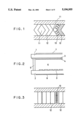
- the layers of the liquid crystal are arranged in parallel to each other and normal to the substrate, and have a tendency of being bent between the substrates as illustrated in FIG. 1.
- the bends appear as undesirable optical defects in controlled molecular orientation at the positions where the directions of bend are changed, resulting in reduction of contrast of images. It is very difficult to remove such bends from the layered structure and the bends continue to degrade the contrast during its operation.
- an electrical torque proportional to ⁇ E 2 (E: external electric field) can be exerted upon the molecules in order to force the directors to be parallel to the surface by applying alternating electric fields between the substrates.
- the torque is exerted upon the molecules, however, in order to inversely erect the directors normal to the substrate if the dielectric anisotropy is positive. Accordingly, there have remained such bends in conventional structures resulting in poor contrast.
- the volume of the liquid crystal material contracts between the substrate as the temperature is descended, often resulting in the formation of void spaces in the layered structure, called tree-like defects. If the viscosity of the liquid crystal is high, the formation of the void space is more likely. While a ferroelectric liquid crystal has a memory characteristic, the viscosity makes it difficult to change the optical property of the liquid crystal material at a selected pixel after the optical property thereof is continuously maintained for a relatively long time, resulting in an afterimage and a poor contrast.
- the voltage level of the control signals applied to the liquid crystal display has been adjusted in accordance with the surrounding temperature to maintain driving performance.
- the electric force ⁇ E 2 is decreased so that undesirable bends tend to remain.
- the ferroelectric liquid crystal material disposed between a pair of substrates in the device has a coefficient of viscosity of 5000 cps to 30000 cps and a negative dielectric anisotropy at operational temperatures, e.g. between 10° C. and 40° C.
- the liquid crystal consists of a number of layers normal to the substrates.
- the constituent layer in turn consists of liquid crystal molecules arranged parallel to the substrates. Misalignment of the molecules yields bends in the layered structure as illustrated in FIG. 1.
- alternating electric fields e.g.
- the molecules are subjected to an electric torque which exerts thereon in order to make the molecules parallel to the substrate by virtue of the negative dielectric anisotropy as illustrated in FIG. 3.
- the realigning action of the electric torque is made ineffective when the coefficient of viscosity of the liquid crystal exceeds 30000 cps.
- the thickness of an orientation control film is preferably selected to be no larger than 200 ⁇ so as not to collect undersirable electric charge on the surface of the film.
- alternating driving signals are applied to the liquid crystal layers.
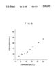
- the frequency of the signal is adjusted in accordance with the temperature of the liquid crystal. This adjustment of the frequency is equivalent to the control of the effective voltage of the driving signals. In actual cases, the frequency is increased as the temperature increases.
- the contrast ratio is maintained no lower than 10 between -3° C. and 40° C. Accordingly the contrast ratio is maintained no lower than 10 also in the usual operation temperature range of 10° C. to 40° C.
- FIG. 1 is a schematic diagram showing undesirable bends of liquid crystal layers.
- FIG. 3 is an explanatory view showing liquid crystal layers in accordance with the present invention.
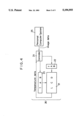
- FIG. 4 is a block diagram showing an experimental system used in an embodiment of the present invention.
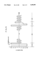
- FIG. 5 is a graph showing a waveform of a voltage applied to a liquid crystal in accordance with the present invention.
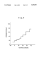
- FIG. 7 is a graph showing a relationship between temperature and frequency of the voltage in accordance with the present invention.
- LCD liquid crystal display
- Suitable rubbing treatment is given to the polyimide films 4 by means of a cotton cloth applied to a roller in order to form an orientation control surface.
- Spacers consisting of hard particles of 2 ⁇ m diameter are applied to the inside surface of the substrate 2.
- the peripheral inside of the substrate 1 is provided with a sealing member 5 made of an epoxy-based thermosetting adhesive by screen printing.
- the pair of these substrates 1 and 2 are joined with the adhesive therebetween and heated under pressure in order to harden the adhesive.
- a ferroelectric liquid crystal is disposed between the substrates 1 and 2 through an opening provided in the sealing member 5, which is closed thereafter by means of a UV-light setting resin.
- a pair of polarizing plates 7 and 8 are placed on the opposite outside surfaces of the substrates.
- An experimental system 26 is fabricated which comprises the liquid crystal display (LCD) 21, a TAB (tape-automated-bonding) 22, a TAB 23, a controller 24, and a personal computer system 25 as illustrated in FIG. 4.
- Image data are supplied from the personal computer system 25.
- Temperature data are obtained by detecting temperature of the liquid crystal 6 of the display 21.
- the controller 24 receives the image data and temperature data.
- the controller 24 supplies driving signals through the TABs 22 and 23 to the display 21 in response to the received image data and temperature data.
- the ferroelectric liquid crystal is driven by alternating voltages. For example, an alternating voltage shown in FIG. 5 is applied to a picture element of the display 21 when a temperature of the liquid crystal of the display 21 is 10° C.
- the frequency of this alternating voltage is 25 kHz (1/25000 second) as shown in FIG. 5.
- voltage levels are +20 V and -20 V during period (A) and +20 V, -20 V, -10 V, and +10 V during period (C) and +5 V and - 5 V during period (B) and period (D).
- Frequency of alternating voltage is controlled by the controller 24 in response to temperature data received by the controller 24 from the display 21. Frequency employed in this preferred embodiment is monotonically increased as temperature of the liquid crystal of the display 21 increases.
- the dielectric anisotropy of the liquid crystal was measured to be -0.8 (10° C.) and -0.3 (40° C.) and the coefficient of viscosity thereof was 25000 cps (10° C.) and 6000 cps (40° C.).
- the contrast ratio was maintained between 30 and 19 even if the temperature was elevated from -3° C. to 40° C.
- the contrast ratio was 25 at 10° C.
- a high contrast white-black display was realized by virtue of control of frequency of the alternating voltage, so that very clear images could be observed.
- the liquid crystal was replaced, for reference, by another liquid crystal whose dielectric anisotropy was -0.6 (10° C.), 0 (approx. 29° C.) and 0.4 (40° C.).
- the contrast ratio was significantly decreased to 7 to 9 at high temperatures no lower than 30° C. while being as high as 16 to 18 at low temperatures between 10° C. and 30° C., indicative of undesirable temperature dependence of performance.
- the liquid crystal was replaced by a further different liquid crystal which exhibited its negative dielectric anisotropy in the same manner as the above preferred embodiment but exhibited its high viscosity, the contrast ratio was as low as 6 to 8 at low temperatures although high contrast images were maintained at high temperatures.
- the voltage level of the driving signals in case of white display was controlled between ⁇ 10 V and ⁇ 20 V and the maximum voltage level in case of black display was controlled between ⁇ 10 V and ⁇ 20 V to cope with the temperature change for reference instead of the adjustment of the frequency.
- the frequency of the signal was kept constant (25 kHz) in this case.
- the contrast ratio was significantly degraded from 25 at 10° C. to 8 at 40° C.
Abstract
Description
Claims (10)
Applications Claiming Priority (4)
| Application Number | Priority Date | Filing Date | Title |
|---|---|---|---|
| JP2-134442 | 1990-05-24 | ||
| JP13444290A JPH0429115A (en) | 1990-05-24 | 1990-05-24 | Method for driving liquid crystal electrooptical device |
| JP13444190A JPH0429119A (en) | 1990-05-24 | 1990-05-24 | Ferroelectric liquid crystal electrooptical device |
| JP2-134441 | 1990-05-24 |
Publications (1)
| Publication Number | Publication Date |
|---|---|
| US5196955A true US5196955A (en) | 1993-03-23 |
Family
ID=26468558
Family Applications (1)
| Application Number | Title | Priority Date | Filing Date |
|---|---|---|---|
| US07/703,097 Expired - Fee Related US5196955A (en) | 1990-05-24 | 1991-05-22 | Ferroelectric liquid crystal optical device with viscosity not more than 30000 cps |
Country Status (1)
| Country | Link |
|---|---|
| US (1) | US5196955A (en) |
Cited By (2)
| Publication number | Priority date | Publication date | Assignee | Title |
|---|---|---|---|---|
| US5742369A (en) * | 1993-12-28 | 1998-04-21 | Canon Kabushiki Kaisha | Method of aligning liquid crystals by applying an alternating electric field under periodically changing temperature |
| US5798814A (en) * | 1990-08-28 | 1998-08-25 | Semiconductor Energy Laboratory Co., Ltd. | Method of driving a ferroelectric liquid crystal optical device |
Citations (5)
| Publication number | Priority date | Publication date | Assignee | Title |
|---|---|---|---|---|
| US4902107A (en) * | 1985-04-26 | 1990-02-20 | Canon Kabushiki Kaisha | Ferroelectric liquid crystal optical device having temperature compensation |
| US4917469A (en) * | 1987-07-18 | 1990-04-17 | Stc Plc | Addressing liquid crystal cells |
| US4923285A (en) * | 1985-04-22 | 1990-05-08 | Canon Kabushiki Kaisha | Drive apparatus having a temperature detector |
| US5033822A (en) * | 1988-08-17 | 1991-07-23 | Canon Kabushiki Kaisha | Liquid crystal apparatus with temperature compensation control circuit |
| US5071589A (en) * | 1987-09-19 | 1991-12-10 | Hoechst Aktiengesellschaft | Liquid-crystalline mixtures, in particular ferroelectric liquid-crystalline mixtures |
-
1991
- 1991-05-22 US US07/703,097 patent/US5196955A/en not_active Expired - Fee Related
Patent Citations (5)
| Publication number | Priority date | Publication date | Assignee | Title |
|---|---|---|---|---|
| US4923285A (en) * | 1985-04-22 | 1990-05-08 | Canon Kabushiki Kaisha | Drive apparatus having a temperature detector |
| US4902107A (en) * | 1985-04-26 | 1990-02-20 | Canon Kabushiki Kaisha | Ferroelectric liquid crystal optical device having temperature compensation |
| US4917469A (en) * | 1987-07-18 | 1990-04-17 | Stc Plc | Addressing liquid crystal cells |
| US5071589A (en) * | 1987-09-19 | 1991-12-10 | Hoechst Aktiengesellschaft | Liquid-crystalline mixtures, in particular ferroelectric liquid-crystalline mixtures |
| US5033822A (en) * | 1988-08-17 | 1991-07-23 | Canon Kabushiki Kaisha | Liquid crystal apparatus with temperature compensation control circuit |
Cited By (2)
| Publication number | Priority date | Publication date | Assignee | Title |
|---|---|---|---|---|
| US5798814A (en) * | 1990-08-28 | 1998-08-25 | Semiconductor Energy Laboratory Co., Ltd. | Method of driving a ferroelectric liquid crystal optical device |
| US5742369A (en) * | 1993-12-28 | 1998-04-21 | Canon Kabushiki Kaisha | Method of aligning liquid crystals by applying an alternating electric field under periodically changing temperature |
Similar Documents
| Publication | Publication Date | Title |
|---|---|---|
| US4744639A (en) | Ferroelectric liquid crystal device having a flattening layer | |
| US5786879A (en) | Liquid crystal device with different pretilt in peripheral portion | |
| US6344889B1 (en) | Liquid crystal display and method of manufacturing the same | |
| US5838410A (en) | Optical modulation element | |
| JP3144329B2 (en) | Liquid crystal display device | |
| US5196955A (en) | Ferroelectric liquid crystal optical device with viscosity not more than 30000 cps | |
| EP1246158B1 (en) | Display unit for displaying moving pictures | |
| US5760863A (en) | DHF ferroelectric liquid crystalline display, switching or image processing apparatus | |
| JPH03243915A (en) | Liquid crystal light valve | |
| EP0775930A2 (en) | Liquid crystal display apparatus | |
| US5798814A (en) | Method of driving a ferroelectric liquid crystal optical device | |
| JPH03242624A (en) | Liquid crystal light valve device | |
| JP2791345B2 (en) | Ferroelectric liquid crystal panel | |
| JP3657708B2 (en) | Liquid crystal electro-optical device | |
| JP3184761B2 (en) | Liquid crystal element, image display apparatus and image forming apparatus including the same | |
| JP3054906B2 (en) | Liquid crystal element and display device using the same | |
| JP3329721B2 (en) | Liquid crystal display | |
| JP3029179B2 (en) | Liquid crystal element | |
| JP3135724B2 (en) | Liquid crystal electro-optical device | |
| JP2000029000A (en) | Method for driving antiferroelectric liquid crystal display device | |
| JP3326161B2 (en) | Driving method of electro-optical device | |
| JP3378038B2 (en) | Driving method of electro-optical device | |
| JP3083021B2 (en) | Ferroelectric liquid crystal device | |
| JPH11231340A (en) | Liquid crystal display device | |
| JP2974420B2 (en) | Ferroelectric liquid crystal element, liquid crystal display element, liquid crystal display device and recording device |
Legal Events
| Date | Code | Title | Description |
|---|---|---|---|
| AS | Assignment |
Owner name: TAKASAGO INTERNATIONAL COOPERATION, JAPAN Free format text: ASSIGNMENT OF ASSIGNORS INTEREST.;ASSIGNORS:KONUMA, TOSHIMITSU;YAMAZAKI, SHUNPEI;HAGIWARA, TOSHIMITSU;AND OTHERS;REEL/FRAME:005780/0329;SIGNING DATES FROM 19910612 TO 19910620 Owner name: SEMICONDUCTOR ENERGY LABORATORY CO., LTD., JAPAN Free format text: ASSIGNMENT OF ASSIGNORS INTEREST.;ASSIGNORS:KONUMA, TOSHIMITSU;YAMAZAKI, SHUNPEI;HAGIWARA, TOSHIMITSU;AND OTHERS;REEL/FRAME:005780/0329;SIGNING DATES FROM 19910612 TO 19910620 |
|
| AS | Assignment |
Owner name: SEMICONDUCTOR ENERGY LABORATORY CO., LTD. Free format text: CORRECTIVE ASSIGNMENT RE-RECORDED TO CORRECT THE NAME OF SECOND ASSIGNEE, PREVIOUSLY RECORDED ON REEL 5780, FRAME 0329;ASSIGNORS:KONUMA, TOSHIMITSU;YAMAZAKI, SHUNPEI;HAIGWARA, TOSIMITSU;AND OTHERS;REEL/FRAME:005864/0476;SIGNING DATES FROM 19910702 TO 19910709 Owner name: TAKASAGO INTERNATIONAL CORPORATION Free format text: CORRECTIVE ASSIGNMENT RE-RECORDED TO CORRECT THE NAME OF SECOND ASSIGNEE, PREVIOUSLY RECORDED ON REEL 5780, FRAME 0329;ASSIGNORS:KONUMA, TOSHIMITSU;YAMAZAKI, SHUNPEI;HAIGWARA, TOSIMITSU;AND OTHERS;REEL/FRAME:005864/0476;SIGNING DATES FROM 19910702 TO 19910709 |
|
| FEPP | Fee payment procedure |
Free format text: PAYOR NUMBER ASSIGNED (ORIGINAL EVENT CODE: ASPN); ENTITY STATUS OF PATENT OWNER: LARGE ENTITY |
|
| FPAY | Fee payment |
Year of fee payment: 4 |
|
| FPAY | Fee payment |
Year of fee payment: 8 |
|
| REMI | Maintenance fee reminder mailed | ||
| LAPS | Lapse for failure to pay maintenance fees | ||
| STCH | Information on status: patent discontinuation |
Free format text: PATENT EXPIRED DUE TO NONPAYMENT OF MAINTENANCE FEES UNDER 37 CFR 1.362 |
|
| FP | Lapsed due to failure to pay maintenance fee |
Effective date: 20050323 |