US5195261A - Quick-hitching device for detachably mounting an attachment to a vehicle frame - Google Patents
Quick-hitching device for detachably mounting an attachment to a vehicle frame Download PDFInfo
- Publication number
- US5195261A US5195261A US07/868,963 US86896392A US5195261A US 5195261 A US5195261 A US 5195261A US 86896392 A US86896392 A US 86896392A US 5195261 A US5195261 A US 5195261A
- Authority
- US
- United States
- Prior art keywords
- frame
- hitching
- sub
- attachment
- quick
- Prior art date
- Legal status (The legal status is an assumption and is not a legal conclusion. Google has not performed a legal analysis and makes no representation as to the accuracy of the status listed.)
- Expired - Lifetime
Links
Images


Classifications
-
- E—FIXED CONSTRUCTIONS
- E01—CONSTRUCTION OF ROADS, RAILWAYS, OR BRIDGES
- E01H—STREET CLEANING; CLEANING OF PERMANENT WAYS; CLEANING BEACHES; DISPERSING OR PREVENTING FOG IN GENERAL CLEANING STREET OR RAILWAY FURNITURE OR TUNNEL WALLS
- E01H5/00—Removing snow or ice from roads or like surfaces; Grading or roughening snow or ice
- E01H5/04—Apparatus propelled by animal or engine power; Apparatus propelled by hand with driven dislodging or conveying levelling elements, conveying pneumatically for the dislodged material
- E01H5/06—Apparatus propelled by animal or engine power; Apparatus propelled by hand with driven dislodging or conveying levelling elements, conveying pneumatically for the dislodged material dislodging essentially by non-driven elements, e.g. scraper blades, snow-plough blades, scoop blades
- E01H5/065—Apparatus propelled by animal or engine power; Apparatus propelled by hand with driven dislodging or conveying levelling elements, conveying pneumatically for the dislodged material dislodging essentially by non-driven elements, e.g. scraper blades, snow-plough blades, scoop blades characterised by the form of the snow-plough blade, e.g. flexible, or by snow-plough blade accessories
- E01H5/066—Snow-plough blade accessories, e.g. deflector plates, skid shoes
-
- E—FIXED CONSTRUCTIONS
- E01—CONSTRUCTION OF ROADS, RAILWAYS, OR BRIDGES
- E01H—STREET CLEANING; CLEANING OF PERMANENT WAYS; CLEANING BEACHES; DISPERSING OR PREVENTING FOG IN GENERAL CLEANING STREET OR RAILWAY FURNITURE OR TUNNEL WALLS
- E01H5/00—Removing snow or ice from roads or like surfaces; Grading or roughening snow or ice
- E01H5/04—Apparatus propelled by animal or engine power; Apparatus propelled by hand with driven dislodging or conveying levelling elements, conveying pneumatically for the dislodged material
- E01H5/06—Apparatus propelled by animal or engine power; Apparatus propelled by hand with driven dislodging or conveying levelling elements, conveying pneumatically for the dislodged material dislodging essentially by non-driven elements, e.g. scraper blades, snow-plough blades, scoop blades
Definitions
- the present invention relates to a quick-hitching device for detachably mounting in a quick and very efficient manner, a vehicle attachment such as a snow-plow, to the frame of a road vehicle, preferably a 2 or 4 wheel drive vehicle.
- the known devices comprise a framework that is detachably connectable to the frame of the truck.
- the snow plow is detachably mounted in pivotably adjustable manner onto the front of the frame of the vehicle so as to transfer the plowing force directly to this framework.
- a hydraulic cylinder is provided for moving the plow from its plowing position to a raised position.
- This cylinder is generally secured to the frame of the truck with mounting brackets and arms extending therefrom and to which are attached chains or other means for lifting the plow blade out of contact with the ground.
- the known devices also have the disadvantage of requiring a bulky attachment frame permanently secured to the truck, for use to connect the device.
- This attachment frame often creates encumbrance to the vehicle when the snow plow is not attached thereto, and it adds to the weight of the vehicle, thereby increasing its fuel consumption. Further, it often damages the vehicle frame to which it is permanently attached.
- a first object of the present invention is to provide a universal quick hitching device to detachably mount an attachment to the frame of a road vehicle.
- Another object of the invention is to provide a device of the above type, which is very simplified and very easy to install as compared to the existing device.
- a further object of the invention is to provide a device of the above type, which is so designed as to reduce the time required to mount and remove the attachment.
- Still another object of the invention is to provide a device of the above type, which requires only one operator to mount and remove the attachment to and from the vehicle.
- Still another object of the invention is to provide a device of the above type, wherein the appearance of the vehicle is not permanently deteriorated by a front attachment frame and a deplaced bumper.
- Still a further object of the invention is to provide a device of the above type, including a permanent attachment frame which does not extend forward at the front of the vehicle, thereby decreasing the safety hazards.
- a quick hitching device for detachably mounting an attachment such as a snow plow or a rotary brush to the frame of a road vehicle, the device comprising:
- a quick hitching sub-frame detachably coupledble to the frame of the vehicle, this quick hitching sub-frame having a rear portion including longitudinally spaced-apart front and rear hitching means detachably connectable to the bottom of the vehicle frame, the quick hitching sub-frame being tiltable with respect to the vehicle frame about a first transversal axis when the front hitching means are connected to the vehicle frame but the rear h itching means is not, the hitching sub-frame also having a front portion projecting up vertically in front of the rear portion;
- an attachment supporting sub-frame having a rear end hingedly connected to the rear portion of the hitching sub-frame, in front of he front hitching means, about a second transversal axis parallel to the first transversal axis, the supporting frame having a front end including means for mounting the attachment;
- a longitudinal extensible power jack having one end pivotably atached to the front portion of the hitching sub-frame above the second transversal axis, and another end pivotably attached to the front end of the supporting sub-frame, the power jack being actuable to cause the supporting sub-frame to be tilted up and down with respect to the hitching sub-frame between a first extreme position where both of the sub-frames are folded to form an inverted V, with the second transversal axis extending above the ground and the front hiching means extending up to the frame of the vehicle, and a second extreme position where the hitching sub-frame is fully connected to the vehicle frame and the supporting sub-frame is tilted up to lift up the attachment mounted thereon in an inactive position, the attachment being in active position between said first and second extreme positions.
- the device according to the invention is made in such a way that it lifts up and lowers by itself to reach the vehicle frame and move down from the same.
- one person only may without effort and tools and in a very short time, connect or disconnect this quick-hitching device to or from the vehicle frame, thereby eliminating the weight of a permanent attachment and avoiding any deterioration to the appearance of the vehicle.
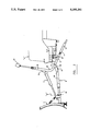
- FIG. 1 is a front perspective view of a quick-hitching device according to the invention
- FIG. 2 is a side elevational view of the quick-hitching device of FIG. 1 in another extreme position;
- FIG. 3 is a side elevational view of the quick-hitching device of FIG. 1 in another extreme position;
- FIG. 4 is a top plan view showing the supporting and hitching sub-frames of the quick-hitching device shown in FIGS. 1 to 3; its supporting and hitching sub-frames;
- FIG. 5 is a perspective view of the front hitching means
- FIG. 8 is a front elevational view of the portion of the rear hitching means fixed to the vehicle frame.
- FIG. 9 is a front elevational view of the hydraulic quick coupler and electric switch support fixed to the front of the vehicle.
- the quick hitching device 1 is intented to be used for detachably mounting an attachment such as a snow plow 3 to the frame 5 of a road vehicle V, such as a 4 ⁇ 4 or a pick-up.
- the hitching sub-frame 7 comprises a pair of longitudinally extending, L-shaped frame members 13, 13' that extend parallel each in a vertical plane and are rigidly connected to each other by means of transversal frame members 15, 15', 15" (see FIG. 4). These L-shaped frame members 13, 13' have horizontal arms 17, 17' that are rearwardly oriented. These arms 17, 17' that together define the rear portion of the hitching sub-frame 7, are bent toward each other at the rear end 19 of the hitching sub-frame 7 to give a V-shape to this rear end.
- the L-shaped frame members 13, 13' also have vertical arms 19, 19' that projects vertically at the front end of the rear portion of the hitching sub-frame 7 and, these arms 19, 19' together defining the front portion of the sub-frame 7.
- the rear portion of the hitching sub-frame 7 includes longitudinally spaced-apart, front and rear hitching means detachably connectable to the bottom of the vehicle frame 5.
- the front hitching means comprises a pair of transversally extending, coaxially positioned, pin-receiving tubings 21, 21' fixed by means of plates 22, 22' to the frame 5 of the vehicle under the same, so as to extend above the horizontal arms 17, 17' of the L-shaped frame members 13, 13' when the hitching sub-frame 7 is longitudinally positioned in hitching position under the vehicle frame.
- the front hitching means also comprises a pair of longitudinally extending cheek plates 23, 23' vertically projecting from each of the horizontal arms 17, 17' of the L-shaped frame members 13, 13'.
- Each pair of cheek plates, say those numbered 23, is perforated by transversal hole 24 and forms a longitudinal yoke in which one of the tubings, say 21, may transversally engage as is shown in FIG. 5.
- the cheek plates 23, 23' of each pair have upper edges that are outwardly flaring, and inner walls that are provided with V-shaped guiding means 25 to allow self-positioning of the corresponding tubing 21 in line with the holes 24 made in the cheek plates.
- the front and rear hitching means disclosed hereinabove are mounted and positioned in such a manner as to allow the hitching sub-frame 7 to be tilted with respect to the vehicle frame 5 about a first transversal axis "X" coaxial with the pins 27, 27' when the front hitching means are connected to the vehicle frame but the rear hitching means is not.
- the attachment supporting sub-frame 9 comprises a ⁇ -shaped frame 35 having a rear base 37 hingedly connected to the front end of the rear position of the hitching sub-frame 7, in front of the front hitching means.
- the connection is made by a pair of opposite vertical mounting plates 39, 39' and a pair of pivots 41, 41' that are coaxial and form a second transversal axis "Y" parallel to the axis "X" passing through the pins 27, 27'.
- the pivots 41, 41' vertically connect the mounting plates to the horizontal arms 17, 17' defining the rear portion of the hitching sub-frame 7, close to the front end of this rear portion.
- the frame 35 of the sub-frame 9 also has an apex 43 to which the snow-blade 3 is pivotably connected about a vertical axis Z, by suitable mounting means known per se.
- the power jack 11 operatively connecting both sub-frames 7, 9 extends in a longitudinal plane which itself extends vertically centrally with respect to the device 1.
- This power jack 11 has one end 47 pivotably attached to the front portion of the hitching sub-frame 7 above the second transversal axis Y and another end 49 pivotably attached to the front end 43 of the ⁇ -shaped frame 35 of the supporting sub-frame 9.
- the end 47 of the power jack 11 is pivotably attached to the front portion of the hitching sub-frame 7 via a pivot mechanism including a lever arm 51 consisting of two parallel plates that are movable in unison in the same vertical plane as the power jack 11.
- the purpose of this lever arm 51 is to increase the stroke of the power jack 51 whenever desired.
- This arm 51 has one end pivotably connected by a hinge 53 to a pair of vertical plates 54 rigidly mounted between the transversal frame member 15' and a holding bar 55 extending horizontally between the vertical arms 19, 19' of the hitching sub-frame 9 at substantially mid-height thereof.
- the other end 57 of the lever arm 51 is pivotably connected to the end 47 of the power jack 11.
- the holding bar 55 acts as a stopping means to stop the lever arm 51 in a stop position where this lever arm is moved frontwardly downwardly and reaches a downwardly extending position.
- the power jack 11 is mounted in such a manner as to cause the supporting sub-frame 9 to be tilted up and down with respect to said hitching sub-frame 7 between a first extreme position shown in FIG. 2 where both sub-frames 7, 9 are folded to form an inverted V, with the second transversal axis extending above the ground and the front hitching means extending up to the frame 5 of the vehicle, and a second extreme position shown in FIG. 3 where the hitching sub-frame 7 is fully connected to the vehicle fame 5 and the supporting sub-frame 9 is tilted up to lift up the attachment 3 mounted thereon in an inactive position.
- the attachment is in active position when the sub-frames are positioned by the power jack 11 between these first and second extreme positions.
- the power jack 11 is preferably hydraulic and operatively connected to a hydraulic power source (not shown) mounted within vehicle. Such a connection can be achieved with quick couplers 71 fixed to the front bumper 73 of the vehicle (see FIGS. 1 and 10).
- the jack 11 is manually operable from the outside and inside of the vehicle by means of easy-to-reach control means, such as a first switch 75 fixed to the front bumper 73 close to the quick couplers, and a second switch (not shown) located inside the vehicle cabin.
- the first switch 75 makes it possible for the operator to actuate the device 1 and lift up and lower from the exterior, the hitching sub-frame 7 to attach and detach it from the vehicle.
- the operator has first to advance over the hitching sub-frame 7 with the vehicle and attach the hoses of the power jack 11 to the hydraulic quick couplers 4.
- the lever arm 51 is pivoted downward against the stopping pin 59 and the power jack 11 is actuated to lift up the front portion of the sub-frame 7, while ensuring that the yoke-defining cheek plates 23, 23' are in line with the tubings 21, 21'.
- the guiding means 25 inside the yoke defining cheek plates 23, 23' will automatically align the tubings with the holes 24, making them ready to be locked with the spring biased locking pins 27, 27' attached to the sub-frame 7.
- the operator retracts the power jack 11, thereby causing pivoting of the lever arm 51 to a position where it will be aligned with the power jack 11.
- the rod end of power jack 11 will pull up the attachment sub-frame 9 and the hitching sub-frame 7 will rotate about the axis X and be lifted up in a position where its rear end will be ready to be locked with the locking bolt 29.
- the operator may then activate the switch 75 while he lifts with the other hand the lever arm 51 and the power jack 11.
- the power jack 11 When the power jack 11 extends longitudinally, it pushes the lever arm 51 in the up position D shown in FIG. 6, where the locking pin 61 may be inserted into the hole 63 on top of the front portion of the hitching sub-frame 7.
- the quick hitching device 1 may further comprising head lights 77 attached on top of the front portion of the hitching sub-frame 7. These head lights 77 may be connected by a plug to an electric outlet 79 mounted adjacent the switch 75 (see FIG. 10). The head lights 77 are attached onto supporting posts along which they are adjustable in height and angle.
Landscapes
- Engineering & Computer Science (AREA)
- Architecture (AREA)
- Civil Engineering (AREA)
- Structural Engineering (AREA)
- Vehicle Cleaning, Maintenance, Repair, Refitting, And Outriggers (AREA)
Abstract
Description
Claims (13)
Priority Applications (1)
| Application Number | Priority Date | Filing Date | Title |
|---|---|---|---|
| US07/868,963 US5195261A (en) | 1992-04-16 | 1992-04-16 | Quick-hitching device for detachably mounting an attachment to a vehicle frame |
Applications Claiming Priority (1)
| Application Number | Priority Date | Filing Date | Title |
|---|---|---|---|
| US07/868,963 US5195261A (en) | 1992-04-16 | 1992-04-16 | Quick-hitching device for detachably mounting an attachment to a vehicle frame |
Publications (1)
| Publication Number | Publication Date |
|---|---|
| US5195261A true US5195261A (en) | 1993-03-23 |
Family
ID=25352650
Family Applications (1)
| Application Number | Title | Priority Date | Filing Date |
|---|---|---|---|
| US07/868,963 Expired - Lifetime US5195261A (en) | 1992-04-16 | 1992-04-16 | Quick-hitching device for detachably mounting an attachment to a vehicle frame |
Country Status (1)
| Country | Link |
|---|---|
| US (1) | US5195261A (en) |
Cited By (48)
| Publication number | Priority date | Publication date | Assignee | Title |
|---|---|---|---|---|
| US5479730A (en) * | 1994-06-06 | 1996-01-02 | Gogan; James R. | Snowblower attachment for a pickup truck |
| US5509219A (en) * | 1994-11-02 | 1996-04-23 | Mecca; Leonard W. | Light weight portable snow plow |
| US5558169A (en) * | 1995-02-13 | 1996-09-24 | Kenneth B. Madgwick | Truck mounted work implement |
| US5568694A (en) * | 1993-12-15 | 1996-10-29 | M. J. Electric, Inc. | Behind the bumper, quick attachment system and mechanism for truck mounted snow plows |
| US5588232A (en) * | 1993-09-04 | 1996-12-31 | Pearson Engineering Limited | Vehicle linkage |
| US5706591A (en) * | 1996-03-13 | 1998-01-13 | Wissmiller; Joseph E. | Hitch for a moldboard snow plow |
| US5815956A (en) * | 1996-04-30 | 1998-10-06 | Curtis International , Inc. | Vehicle mounting assembly for a snow plow with hidden actuator drive |
| US5829174A (en) * | 1994-04-08 | 1998-11-03 | Sno-Way International, Inc. | Articulated snowplow system |
| US5832637A (en) * | 1993-04-26 | 1998-11-10 | Aguado; Aleck P. | Method of operating a snowplow |
| US5924223A (en) * | 1998-06-11 | 1999-07-20 | Hone, Jr.; Frederick T. | Snowplow with a hydraulically assisted mounting system |
| US5997024A (en) * | 1998-04-07 | 1999-12-07 | Deere & Company | Hitch mechanism |
| US6050008A (en) * | 1996-09-13 | 2000-04-18 | Douglas Dynamics, L.L.C. | Vehicle mounted accessory assembly |
| US6145222A (en) * | 1998-08-14 | 2000-11-14 | Curtis International, Inc. | Vehicle hitch mount assembly for a snow plow |
| US6151808A (en) * | 1998-08-14 | 2000-11-28 | Curtis International, Inc. | Jack for a snow plow |
| US6155359A (en) * | 1999-01-07 | 2000-12-05 | Gardner; John | Vehicle mounted post hole digger |
| US6178669B1 (en) | 1999-02-03 | 2001-01-30 | Blizzard Corporation | Plow hitch assembly for vehicles |
| US6209231B1 (en) | 1998-08-14 | 2001-04-03 | Curtis International, Inc. | Vehicle hitch mount assembly for a snow plow |
| US6240659B1 (en) | 1998-08-14 | 2001-06-05 | Curtis International, Inc. | Control system for jack for a snow plow |
| US6240792B1 (en) * | 1999-05-24 | 2001-06-05 | David R. Elsesser | Support and testing apparatus for snow plow assembly |
| US6286236B1 (en) * | 1999-09-22 | 2001-09-11 | Bowers Designs Inc. | Movable attachment for a zero turning radius prime mover |
| US6321851B1 (en) | 1999-10-28 | 2001-11-27 | Deere & Company | Hitch mechanism for coupling implements to a vehicle |
| US6363629B1 (en) | 2000-02-18 | 2002-04-02 | Curtis International, Inc. | Vehicle hitch mount assembly for a snow plow |
| US6393737B2 (en) | 1999-02-03 | 2002-05-28 | Blizzard Corporation | Plow support assembly |
| US6484421B1 (en) * | 2000-09-27 | 2002-11-26 | John Barry Donoghue | Snow plow assembly |
| US6502334B1 (en) * | 1999-10-29 | 2003-01-07 | Stephen Davies | Attachment for an all terrain vehicle |
| US6526677B1 (en) | 2000-10-06 | 2003-03-04 | Douglas Dynamics, L.L.C. | Snowplow mounting assembly |
| US20040074115A1 (en) * | 2002-09-20 | 2004-04-22 | Curtis Marc D. | Jack for a working implement and method |
| US20040188105A1 (en) * | 2002-03-20 | 2004-09-30 | Patrick Newnam | Method of earthworking |
| US6925735B2 (en) * | 2002-08-30 | 2005-08-09 | Deere & Co. | Bumper, skid plate and attachment system for utility vehicle |
| US20050178029A1 (en) * | 2003-07-23 | 2005-08-18 | Craig Wightman | Attachment for a plow |
| US6944978B2 (en) | 2001-06-11 | 2005-09-20 | Douglas Dynamics, Llc | Snowplow and mount assembly |
| US20060055150A1 (en) * | 2003-09-29 | 2006-03-16 | Ltt Biio-Phara Co., Ltd | Vehicle mount assembly for a utilitarian accessory |
| US20070214683A1 (en) * | 2006-03-03 | 2007-09-20 | Almadani Mazen W | Lost motion mechanism for movable vehicle implements |
| US20080053673A1 (en) * | 2006-08-31 | 2008-03-06 | Michael Dilworth | Plow systems for non-highway vehicles |
| US7513069B1 (en) | 2008-06-17 | 2009-04-07 | Sno-Way International, Inc. | Snow plow jack stand |
| US20090307940A1 (en) * | 2008-06-17 | 2009-12-17 | Maas Andrew J | Height Adjustment on Plow A-Frame |
| US20090307937A1 (en) * | 2008-06-17 | 2009-12-17 | Koch Timothy G | V-Plow |
| US20090307938A1 (en) * | 2008-06-17 | 2009-12-17 | Koch Timothy G | Plow Quick Connect/Disconnect Hitch Mechanism |
| KR100999290B1 (en) | 2010-07-22 | 2010-12-07 | 서울특별시 서대문구 | Snow plow |
| US8061063B2 (en) | 2008-06-17 | 2011-11-22 | Sno-Way International, Inc. | Plow wing blade |
| US20120297762A1 (en) * | 2010-11-17 | 2012-11-29 | Liebherr-Hydraulikbagger Gmbh | Implement |
| US9169617B2 (en) | 2011-10-14 | 2015-10-27 | Nordic Auto Plow, Llc | Plow for use with automobile |
| US9347199B2 (en) | 2012-02-21 | 2016-05-24 | Soucy International Inc. | Support frame for an implement |
| US9593465B2 (en) | 2010-11-17 | 2017-03-14 | Liebherr-Hydraulikbagger Gmbh | Heat exchanger for energy recovery cylinder |
| US9845581B2 (en) | 2011-10-14 | 2017-12-19 | Nordic Auto Plow, Llc | Plow for use with automobiles and other vehicles |
| US9869067B2 (en) | 2014-11-13 | 2018-01-16 | Douglas Dynamics, L.L.C. | Snow plow and mount assembly |
| US11499280B2 (en) | 2019-06-26 | 2022-11-15 | Douglas Dynamics, L.L.C. | Snow plow and mount assembly |
| US11555282B2 (en) | 2019-06-26 | 2023-01-17 | Douglas Dynamics, Llc | Snow plow and mount assembly |
Citations (12)
| Publication number | Priority date | Publication date | Assignee | Title |
|---|---|---|---|---|
| US3769724A (en) * | 1969-12-08 | 1973-11-06 | R Norgaard | Plow blade hoist with under-truck mount |
| US3845577A (en) * | 1973-11-23 | 1974-11-05 | M Naymik | Lightweight snowplow for quick attachment to small vehicle |
| US4236329A (en) * | 1979-07-12 | 1980-12-02 | Meyer Products, Inc. | Detachable blade mounting device |
| US4244122A (en) * | 1979-06-04 | 1981-01-13 | Meyer Products, Inc. | Modified power unit for snow plows |
| US4279084A (en) * | 1979-11-15 | 1981-07-21 | Meyer Products, Inc. | Snowplow blade lift mount assembly |
| US4320589A (en) * | 1978-05-26 | 1982-03-23 | Andrea Pelazza | Snowplow apparatus |
| US4342163A (en) * | 1980-09-02 | 1982-08-03 | Swenson Spreader Company | Apparatus for mounting a snowplow blade to a vehicle |
| CA1153885A (en) * | 1982-10-08 | 1983-09-20 | Lucien Cote | Snow plow attachment |
| US4619060A (en) * | 1985-07-02 | 1986-10-28 | Knowlton Leland P | Plow coupling |
| CA1276784C (en) * | 1986-09-03 | 1990-11-27 | Tenco Machinery Ltd. | Mechanism for detachably mounting a plow system to a land vehicle |
| US5036608A (en) * | 1990-02-26 | 1991-08-06 | The Louis Berkman Company | Snowplow quick mount lift assembly |
| US5075988A (en) * | 1990-02-26 | 1991-12-31 | The Louis Berkman Company | Snowplow quick mount lift assembly |
-
1992
- 1992-04-16 US US07/868,963 patent/US5195261A/en not_active Expired - Lifetime
Patent Citations (12)
| Publication number | Priority date | Publication date | Assignee | Title |
|---|---|---|---|---|
| US3769724A (en) * | 1969-12-08 | 1973-11-06 | R Norgaard | Plow blade hoist with under-truck mount |
| US3845577A (en) * | 1973-11-23 | 1974-11-05 | M Naymik | Lightweight snowplow for quick attachment to small vehicle |
| US4320589A (en) * | 1978-05-26 | 1982-03-23 | Andrea Pelazza | Snowplow apparatus |
| US4244122A (en) * | 1979-06-04 | 1981-01-13 | Meyer Products, Inc. | Modified power unit for snow plows |
| US4236329A (en) * | 1979-07-12 | 1980-12-02 | Meyer Products, Inc. | Detachable blade mounting device |
| US4279084A (en) * | 1979-11-15 | 1981-07-21 | Meyer Products, Inc. | Snowplow blade lift mount assembly |
| US4342163A (en) * | 1980-09-02 | 1982-08-03 | Swenson Spreader Company | Apparatus for mounting a snowplow blade to a vehicle |
| CA1153885A (en) * | 1982-10-08 | 1983-09-20 | Lucien Cote | Snow plow attachment |
| US4619060A (en) * | 1985-07-02 | 1986-10-28 | Knowlton Leland P | Plow coupling |
| CA1276784C (en) * | 1986-09-03 | 1990-11-27 | Tenco Machinery Ltd. | Mechanism for detachably mounting a plow system to a land vehicle |
| US5036608A (en) * | 1990-02-26 | 1991-08-06 | The Louis Berkman Company | Snowplow quick mount lift assembly |
| US5075988A (en) * | 1990-02-26 | 1991-12-31 | The Louis Berkman Company | Snowplow quick mount lift assembly |
Cited By (88)
| Publication number | Priority date | Publication date | Assignee | Title |
|---|---|---|---|---|
| US6044579A (en) * | 1993-04-26 | 2000-04-04 | Sno-Way International, Inc. | Articulated snowplow system |
| US5987785A (en) * | 1993-04-26 | 1999-11-23 | Sno-Way International, Inc. | Reactive controlled mechanism for a snow-plow |
| US5832637A (en) * | 1993-04-26 | 1998-11-10 | Aguado; Aleck P. | Method of operating a snowplow |
| US5588232A (en) * | 1993-09-04 | 1996-12-31 | Pearson Engineering Limited | Vehicle linkage |
| US5568694A (en) * | 1993-12-15 | 1996-10-29 | M. J. Electric, Inc. | Behind the bumper, quick attachment system and mechanism for truck mounted snow plows |
| US5829174A (en) * | 1994-04-08 | 1998-11-03 | Sno-Way International, Inc. | Articulated snowplow system |
| US5479730A (en) * | 1994-06-06 | 1996-01-02 | Gogan; James R. | Snowblower attachment for a pickup truck |
| US5509219A (en) * | 1994-11-02 | 1996-04-23 | Mecca; Leonard W. | Light weight portable snow plow |
| US5558169A (en) * | 1995-02-13 | 1996-09-24 | Kenneth B. Madgwick | Truck mounted work implement |
| US5870839A (en) * | 1996-03-13 | 1999-02-16 | Wissmiller; Joseph E. | Hitch for a moldboard snow plow |
| US5706591A (en) * | 1996-03-13 | 1998-01-13 | Wissmiller; Joseph E. | Hitch for a moldboard snow plow |
| US5815956A (en) * | 1996-04-30 | 1998-10-06 | Curtis International , Inc. | Vehicle mounting assembly for a snow plow with hidden actuator drive |
| US6050008A (en) * | 1996-09-13 | 2000-04-18 | Douglas Dynamics, L.L.C. | Vehicle mounted accessory assembly |
| US5997024A (en) * | 1998-04-07 | 1999-12-07 | Deere & Company | Hitch mechanism |
| US5924223A (en) * | 1998-06-11 | 1999-07-20 | Hone, Jr.; Frederick T. | Snowplow with a hydraulically assisted mounting system |
| US6408546B2 (en) | 1998-08-14 | 2002-06-25 | Curtis International, Inc. | Vehicle hitch mount assembly for a snow plow |
| US6381880B1 (en) | 1998-08-14 | 2002-05-07 | Curtis International, Inc. | Vehicle hitch mount assembly for a snow plow |
| US6145222A (en) * | 1998-08-14 | 2000-11-14 | Curtis International, Inc. | Vehicle hitch mount assembly for a snow plow |
| US6209231B1 (en) | 1998-08-14 | 2001-04-03 | Curtis International, Inc. | Vehicle hitch mount assembly for a snow plow |
| US6240659B1 (en) | 1998-08-14 | 2001-06-05 | Curtis International, Inc. | Control system for jack for a snow plow |
| US6594924B2 (en) | 1998-08-14 | 2003-07-22 | Curtis International, Inc. | Vehicle hitch mount assembly for a snow plow |
| US6151808A (en) * | 1998-08-14 | 2000-11-28 | Curtis International, Inc. | Jack for a snow plow |
| US6155359A (en) * | 1999-01-07 | 2000-12-05 | Gardner; John | Vehicle mounted post hole digger |
| US6393737B2 (en) | 1999-02-03 | 2002-05-28 | Blizzard Corporation | Plow support assembly |
| US6615513B2 (en) | 1999-02-03 | 2003-09-09 | Blizzard Corporation | Draw latch assembly for mounting a plow to a vehicle |
| US6178669B1 (en) | 1999-02-03 | 2001-01-30 | Blizzard Corporation | Plow hitch assembly for vehicles |
| US6240792B1 (en) * | 1999-05-24 | 2001-06-05 | David R. Elsesser | Support and testing apparatus for snow plow assembly |
| US6286236B1 (en) * | 1999-09-22 | 2001-09-11 | Bowers Designs Inc. | Movable attachment for a zero turning radius prime mover |
| US6321851B1 (en) | 1999-10-28 | 2001-11-27 | Deere & Company | Hitch mechanism for coupling implements to a vehicle |
| US6502334B1 (en) * | 1999-10-29 | 2003-01-07 | Stephen Davies | Attachment for an all terrain vehicle |
| US6363629B1 (en) | 2000-02-18 | 2002-04-02 | Curtis International, Inc. | Vehicle hitch mount assembly for a snow plow |
| US6484421B1 (en) * | 2000-09-27 | 2002-11-26 | John Barry Donoghue | Snow plow assembly |
| US6526677B1 (en) | 2000-10-06 | 2003-03-04 | Douglas Dynamics, L.L.C. | Snowplow mounting assembly |
| US6711837B2 (en) | 2000-10-06 | 2004-03-30 | Douglas Dynamics, L.L.C. | Snowplow mounting assembly |
| US20050120595A1 (en) * | 2000-10-06 | 2005-06-09 | Douglas Dynamics, L.L.C. | Snowplow mounting assembly |
| US20040172858A1 (en) * | 2000-10-06 | 2004-09-09 | Douglas Dynamics, Inc. | Snowplow mounting assembly |
| US6928757B2 (en) | 2000-10-06 | 2005-08-16 | Douglas Dynamics, L.L.C. | Snowplow mounting assembly |
| US20060010722A1 (en) * | 2001-06-11 | 2006-01-19 | Douglas Dynamics, L.L.C. | Snowplow and mount assembly |
| US7681334B2 (en) * | 2001-06-11 | 2010-03-23 | Batesville Services, Inc. | Snowplow and mount assembly |
| US20100175281A1 (en) * | 2001-06-11 | 2010-07-15 | Douglas Dynamics, Llc | Snowplow and mount assembly |
| US20090031592A1 (en) * | 2001-06-11 | 2009-02-05 | Douglas Dynamics, L.L.C. | Snowplow and mount assembly |
| US6944978B2 (en) | 2001-06-11 | 2005-09-20 | Douglas Dynamics, Llc | Snowplow and mount assembly |
| US7430821B2 (en) | 2001-06-11 | 2008-10-07 | Douglas Dynamics, L.L.C. | Snowplow and mount assembly |
| US7797859B2 (en) * | 2001-06-11 | 2010-09-21 | Douglas Dynamics, L.L.C. | Snowplow and mount assembly |
| US20040188105A1 (en) * | 2002-03-20 | 2004-09-30 | Patrick Newnam | Method of earthworking |
| US6925735B2 (en) * | 2002-08-30 | 2005-08-09 | Deere & Co. | Bumper, skid plate and attachment system for utility vehicle |
| US7103995B2 (en) | 2002-09-20 | 2006-09-12 | Curtis Industries Holdings, Llc | Jack for a working implement and method |
| US7228650B2 (en) | 2002-09-20 | 2007-06-12 | Curtis Industries Llc | Jack for a working implement and method |
| US7260902B2 (en) | 2002-09-20 | 2007-08-28 | Curtis Industries Llc | Jack for a working implement and method |
| US20050076543A1 (en) * | 2002-09-20 | 2005-04-14 | Curtis Marc D. | Jack for a working implement and method |
| US20040074115A1 (en) * | 2002-09-20 | 2004-04-22 | Curtis Marc D. | Jack for a working implement and method |
| US20050066552A1 (en) * | 2002-09-20 | 2005-03-31 | Curtis Marc D. | Jack for a working implement and method |
| US20050178029A1 (en) * | 2003-07-23 | 2005-08-18 | Craig Wightman | Attachment for a plow |
| US20060055150A1 (en) * | 2003-09-29 | 2006-03-16 | Ltt Biio-Phara Co., Ltd | Vehicle mount assembly for a utilitarian accessory |
| US20070214683A1 (en) * | 2006-03-03 | 2007-09-20 | Almadani Mazen W | Lost motion mechanism for movable vehicle implements |
| US7565756B2 (en) | 2006-03-03 | 2009-07-28 | Parker-Hannifin Corporation | Lost motion mechanism for movable vehicle implements |
| US7975407B2 (en) * | 2006-08-31 | 2011-07-12 | Mibar Products Ltd. | Plow systems for non-highway vehicles |
| US20080053673A1 (en) * | 2006-08-31 | 2008-03-06 | Michael Dilworth | Plow systems for non-highway vehicles |
| US8065822B2 (en) | 2008-06-17 | 2011-11-29 | Sno-Way International, Inc. | Height adjustment on plow a-frame |
| US8832974B2 (en) | 2008-06-17 | 2014-09-16 | Sno-Way International, Inc. | V-plow |
| US20090308623A1 (en) * | 2008-06-17 | 2009-12-17 | Koch Timothy G | Blade Adjustment Apparatus |
| US7513069B1 (en) | 2008-06-17 | 2009-04-07 | Sno-Way International, Inc. | Snow plow jack stand |
| US20090307942A1 (en) * | 2008-06-17 | 2009-12-17 | Gamble Ii Robert N | Snow Plow Rebound Apparatus |
| US7836613B2 (en) | 2008-06-17 | 2010-11-23 | Sno-Way International, Inc. | Blade adjustment apparatus |
| US7841110B2 (en) | 2008-06-17 | 2010-11-30 | Sno-Way International, Inc. | Plow quick connect/disconnect hitch mechanism |
| US8499477B2 (en) | 2008-06-17 | 2013-08-06 | Sno-Way International, Inc. | Plow wing blade |
| US7934328B2 (en) | 2008-06-17 | 2011-05-03 | Sno-Way International, Inc. | V-plow cutting edge interface |
| US7963052B2 (en) | 2008-06-17 | 2011-06-21 | Sno-Way International, Inc. | Plow quick connect / disconnect hitch mechanism |
| US20090307937A1 (en) * | 2008-06-17 | 2009-12-17 | Koch Timothy G | V-Plow |
| US7992327B2 (en) | 2008-06-17 | 2011-08-09 | Sno-Way International, Inc. | Snow plow rebound apparatus |
| US8061063B2 (en) | 2008-06-17 | 2011-11-22 | Sno-Way International, Inc. | Plow wing blade |
| US20090307940A1 (en) * | 2008-06-17 | 2009-12-17 | Maas Andrew J | Height Adjustment on Plow A-Frame |
| US20090307938A1 (en) * | 2008-06-17 | 2009-12-17 | Koch Timothy G | Plow Quick Connect/Disconnect Hitch Mechanism |
| US8935862B1 (en) | 2008-06-17 | 2015-01-20 | Sno-Way International, Inc. | V-plow |
| KR100999290B1 (en) | 2010-07-22 | 2010-12-07 | 서울특별시 서대문구 | Snow plow |
| US9644344B2 (en) * | 2010-11-17 | 2017-05-09 | Liebherr-Hydraulikbagger Gmbh | Temperature control of energy recovery cylinder |
| US9593465B2 (en) | 2010-11-17 | 2017-03-14 | Liebherr-Hydraulikbagger Gmbh | Heat exchanger for energy recovery cylinder |
| US20120297762A1 (en) * | 2010-11-17 | 2012-11-29 | Liebherr-Hydraulikbagger Gmbh | Implement |
| US9169617B2 (en) | 2011-10-14 | 2015-10-27 | Nordic Auto Plow, Llc | Plow for use with automobile |
| US9845581B2 (en) | 2011-10-14 | 2017-12-19 | Nordic Auto Plow, Llc | Plow for use with automobiles and other vehicles |
| US9347199B2 (en) | 2012-02-21 | 2016-05-24 | Soucy International Inc. | Support frame for an implement |
| US10017915B2 (en) | 2012-02-21 | 2018-07-10 | Soucy International Inc. | Support frame for an implement |
| US10900183B2 (en) | 2014-11-13 | 2021-01-26 | Douglas Dynamics, L.L.C. | Snow plow and mount assembly |
| US9869067B2 (en) | 2014-11-13 | 2018-01-16 | Douglas Dynamics, L.L.C. | Snow plow and mount assembly |
| US11332899B2 (en) | 2014-11-13 | 2022-05-17 | Douglas Dynamics, L.L.C. | Snow plow and mount assembly |
| US11427978B2 (en) | 2014-11-13 | 2022-08-30 | Douglas Dynamics, L.L.C. | Snow plow and mount assembly |
| US11499280B2 (en) | 2019-06-26 | 2022-11-15 | Douglas Dynamics, L.L.C. | Snow plow and mount assembly |
| US11555282B2 (en) | 2019-06-26 | 2023-01-17 | Douglas Dynamics, Llc | Snow plow and mount assembly |
Similar Documents
| Publication | Publication Date | Title |
|---|---|---|
| US5195261A (en) | Quick-hitching device for detachably mounting an attachment to a vehicle frame | |
| US6988351B2 (en) | Midmount mower apparatus with raiseable and accessible mower deck | |
| US4680880A (en) | Snow plow for small vehicles | |
| US6594924B2 (en) | Vehicle hitch mount assembly for a snow plow | |
| US6209231B1 (en) | Vehicle hitch mount assembly for a snow plow | |
| US5125174A (en) | Removable snowflow with a pivotable lift stand | |
| US6241227B1 (en) | Cutting edge handler for plows and graders | |
| US6594923B1 (en) | Snowplow mount | |
| US6557275B2 (en) | Vehicle hitch mount assembly for a snow plow | |
| US20010037634A1 (en) | Raiseable mower deck | |
| CA2094175C (en) | Vehicle snowplow attachment with spillover gap deflector | |
| US7004454B2 (en) | Motorcycle and small vehicle lift | |
| CA2472266C (en) | Multi-use paving tractor with tool attachments | |
| USRE35700E (en) | Removable snowplow assembly with pivotable lift stand | |
| US2057326A (en) | Snow plow | |
| US3145857A (en) | Mobile lift crane and vehicle tow hoist | |
| SI9400308A (en) | Support device for armoured vehicle | |
| US5727656A (en) | Vehicle lift apparatus | |
| US4714149A (en) | Self propelled auger and separable vehicle therefor | |
| US3941400A (en) | Plow dolly | |
| US20100038181A1 (en) | Portable lift | |
| US5810097A (en) | Attachment system for mounting road-maintenance equipment on a vehicle | |
| US3434732A (en) | Vertically adjustable cattle chute | |
| US5542478A (en) | Combination sloper and tailgrader attachment for vehicles | |
| US6017018A (en) | Lift-a-top plus |
Legal Events
| Date | Code | Title | Description |
|---|---|---|---|
| STCF | Information on status: patent grant |
Free format text: PATENTED CASE |
|
| REMI | Maintenance fee reminder mailed | ||
| FPAY | Fee payment |
Year of fee payment: 4 |
|
| SULP | Surcharge for late payment | ||
| AS | Assignment |
Owner name: CURTIS INTERNATIONAL, INC., MASSACHUSETTS Free format text: ASSIGNMENT OF ASSIGNORS INTEREST;ASSIGNOR:VACHON, BERTRAND;REEL/FRAME:010206/0200 Effective date: 19990816 |
|
| REMI | Maintenance fee reminder mailed | ||
| FPAY | Fee payment |
Year of fee payment: 8 |
|
| SULP | Surcharge for late payment |
Year of fee payment: 7 |
|
| FPAY | Fee payment |
Year of fee payment: 12 |
|
| AS | Assignment |
Owner name: CURTIS INDUSTRIES, LLC, MASSACHUSETTS Free format text: ASSIGNMENT OF ASSIGNORS INTEREST;ASSIGNOR:CURTIS INDUSTRIES HOLDINGS, LLC;REEL/FRAME:017344/0131 Effective date: 20060317 Owner name: CURTIS INDUSTRIES HOLDINGS, LLC, MASSACHUSETTS Free format text: ASSIGNMENT OF ASSIGNORS INTEREST;ASSIGNORS:CURTIS TRACTOR CAB, INC.;CURTIS INTERNATIONAL, INC.;REEL/FRAME:017344/0102 Effective date: 20060317 Owner name: MERRILL LYNCH CAPITAL, AS ADMINISTRATIVE AGENT, IL Free format text: SECURITY AGREEMENT;ASSIGNOR:CURTIS INDUSTRIES, LLC;REEL/FRAME:017344/0169 Effective date: 20060320 |
|
| AS | Assignment |
Owner name: CURTIS INDUSTRIES, LLC, MASSACHUSETTS Free format text: RELEASE BY SECURED PARTY;ASSIGNOR:GE BUSINESS FINANCIAL SERVICES INC. (FORMELY KNOWN AS MERRILL LYNCH BUSINESS FINANCIAL SERVICES INC);REEL/FRAME:026647/0564 Effective date: 20110713 |