US5186261A - On-land plow assembly with a plurality of adjustable plow units - Google Patents
On-land plow assembly with a plurality of adjustable plow units Download PDFInfo
- Publication number
- US5186261A US5186261A US07/720,651 US72065191A US5186261A US 5186261 A US5186261 A US 5186261A US 72065191 A US72065191 A US 72065191A US 5186261 A US5186261 A US 5186261A
- Authority
- US
- United States
- Prior art keywords
- plow
- tractor
- main frame
- plow assembly
- units
- Prior art date
- Legal status (The legal status is an assumption and is not a legal conclusion. Google has not performed a legal analysis and makes no representation as to the accuracy of the status listed.)
- Expired - Lifetime
Links
Images


Classifications
-
- A—HUMAN NECESSITIES
- A01—AGRICULTURE; FORESTRY; ANIMAL HUSBANDRY; HUNTING; TRAPPING; FISHING
- A01B—SOIL WORKING IN AGRICULTURE OR FORESTRY; PARTS, DETAILS, OR ACCESSORIES OF AGRICULTURAL MACHINES OR IMPLEMENTS, IN GENERAL
- A01B3/00—Ploughs with fixed plough-shares
- A01B3/46—Ploughs supported partly by tractor and partly by their own wheels
-
- A—HUMAN NECESSITIES
- A01—AGRICULTURE; FORESTRY; ANIMAL HUSBANDRY; HUNTING; TRAPPING; FISHING
- A01B—SOIL WORKING IN AGRICULTURE OR FORESTRY; PARTS, DETAILS, OR ACCESSORIES OF AGRICULTURAL MACHINES OR IMPLEMENTS, IN GENERAL
- A01B15/00—Elements, tools, or details of ploughs
- A01B15/14—Frames
- A01B15/145—Frames the plough blades being connected to the plough beam for unisono adjustment of the furrow width
-
- A—HUMAN NECESSITIES
- A01—AGRICULTURE; FORESTRY; ANIMAL HUSBANDRY; HUNTING; TRAPPING; FISHING
- A01B—SOIL WORKING IN AGRICULTURE OR FORESTRY; PARTS, DETAILS, OR ACCESSORIES OF AGRICULTURAL MACHINES OR IMPLEMENTS, IN GENERAL
- A01B69/00—Steering of agricultural machines or implements; Guiding agricultural machines or implements on a desired track
- A01B69/003—Steering or guiding of machines or implements pushed or pulled by or mounted on agricultural vehicles such as tractors, e.g. by lateral shifting of the towing connection
- A01B69/004—Steering or guiding of machines or implements pushed or pulled by or mounted on agricultural vehicles such as tractors, e.g. by lateral shifting of the towing connection automatic
Definitions
- the present invention generally relates to farm implements and, more particularly, to an on-land plow assembly including a plurality of adjustable plow units mounted on a common frame and which are pulled across a field by a tractor for simultaneously plowing a plurality of furrows.
- Plow assemblies having a plurality of plow units mounted to a common or main frame which is pulled behind a tractor or other suitable agricultural implement are well known in the art. As is known, each plow unit is mounted at pre-selected intervals along the main frame which is inclined relative to the direction of travel of the tractor. As the plow assembly is pulled across the field, a trailing plow unit will turn plowed earth into a furrow formed by a preceding plow unit.
- a typical plow assembly arranges the plow units behind and such that they are pulled across a field by the tractor.
- a typical plow assembly further includes a steering system including a ground engaging steering wheel conventionally arranged at a rear end of the plow assembly. During a plowing operation, the steering system maintains the steering wheel generally parallel to the tractor wheels. In response to turning of the tractor, the steering system angles the steering wheel thereby facilitating turning of the plow assembly with the tractor.
- An “In-Furrow” plow assembly is typically used with a small type tractor and has three to six plow units arranged in combination therewith. A rear wheel of the tractor is arranged to ride in a previously plowed furrow and, thus, the name "In-Furrow” plow assembly.
- an “In-Furrow” plow assembly is generally restricted to turn approximately 30° to 35° to each side of the direction of travel of the tractor.
- a "On-Land” plow assembly typically includes six or more plow units.
- the additional plow units require a larger size tractor to develop the necessary pulling power for such plow assemblies.
- an "On-Land” plow assembly allows the tractor wheels to ride on-land adjacent a previously plowed furrow.
- the larger tractors sometimes use articulated steering and, thus, provide a shorter turn radius.
- the shorter turn radius of such larger tractors requires the "On-Land” plow assemblies to be designed to turn approximately 60° to 75° to each side of the direction of the tractor.
- a plow assembly adapted to be pulled behind an agricultural implement, such as a tractor, and includes a plurality of plow units, each of which is capable of producing a furrow.
- the plow assembly includes a main frame having a horizontal beam which is inclined relative to the direction of travel of the plow assembly and has the plow units connected thereto.
- the main frame is connected to the tractor about a generally vertical axis allowing the main frame to rotate through an angle in excess of 35° to opposite sides of the direction of movement of the tractor.
- a ground engaging steering wheel is provided at and supports a rear end of the main frame.
- a steering system holds the steering wheel generally parallel to the furrows produced by the plow units and turns the steering wheel through an angle in response and opposite to a steering angle of the tractor to bring the plow assembly around behind the tractor during turns.
- the steering system includes a linkage mechanism for proportionately reducing the turning angle of the steering wheel relative to the steering angle of the tractor thereby allowing the steering angle of the tractor to exceed 35° relative to the direction of travel of the plow assembly while facilitating turning of the plow assembly directly behind the tractor during turns.
- a support mechanism including a ground engaging caster wheel is provided at a forward end of the main frame.
- the support structure for the front caster wheel and rear steering wheel are substantially similar.
- Each support structure preferably includes a power actuated mechanism for vertically moving the respective wheels relative to the main frame.
- a land wheel affixed to the main frame regulates the depth of the furrows produced by the plow units.
- the steering system linkage mechanism or assembly includes a first rotatable arm responsive to the turning angle of the tractor and a second rotatable arm arranged toward a distal end of the main frame and connected to the steering wheel.
- the linkage mechanism proportions the relatively large motion of the first arm and moves the steering wheel an appropriate amount to effect turning of the plow assembly.
- the linkage mechanism proportionately reduces the turning angle of the steering wheel relative to the steering angle of the tractor thereby allowing the tractor to exceed a 35° turn relative to the direction of travel of the plow assembly while still facilitating turning of the plow assembly.
- the linkage mechanism has a series of pivotal connections whose axes establish first and second quadrilateral configurations and furthermore and preferably includes means for adjusting operation of the steering mechanism.
- Another aspect of the present invention relates to the provision of an adjustment mechanism for simultaneously moving the plow units through a continuous range thereby modifying the spacing between adjacent furrows.
- an elongated bar interconnects the plow units for simultaneous movement about their respective vertical axes and such that the furrows produced by the plow units remain generally parallel to each other.
- a control mechanism operable from an operator's station on the tractor, is connected to the elongated bar for selectively moving all of the plow units about their respective vertical axes thereby altering the inclination of the horizontal beam of the main frame relative to the direction of travel and thereby modulating the distance separating the furrows while the plow assembly is pulled by the tractor.
- the steering problem normally associated with plow systems pulled by tractors which turn in excess of 35° relative to the direction of travel of the plow system, is addressed by the present invention through use of a linkage mechanism which proportionately reduces the turning angle of the steering wheel relative to the turning angle of the tractor thereby allowing the tractor to effect turns having a relatively tight steering radius while having the plow assembly follow behind the tractor without damage thereto.
- the steering system of the present invention furthermore automatically maintains the steering wheel parallel to the furrows produced by the plow units for all settings of the spacings between the plow units within the predetermined range.
- the adjustability of the steering system provides that the motion imparted to as well as the responsiveness of the steering wheel may be modified to adapt the plow assembly to changes in operation.
- simultaneous rotation of the plow units causes a change in the inclination of the horizontal beam relative to the direction of movement of the plow assembly thereby changing the spacing between adjacent furrows.
- the operator can save hours of work by adjusting the width between adjacent furrows.
- FIG. 1 is a plan view of a plow assembly according to the present invention attached to a rear end of an agricultural implement such as a tractor;
- FIG. 2 is a side elevational view of the plow assembly of FIG. 1;
- FIG. 3 is an enlarged plan view illustrating a hitch assembly for connecting the plow assembly to the agricultural implement
- FIG. 4 is a side elevational view of the hitch assembly illustrated in FIG. 3;
- FIG. 5 is a sectional view taken along line 5--5 of FIG. 3;
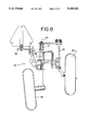
- FIG. 6 is an enlarged side elevational view of support mechanism for the plow assembly of the present invention.
- FIG. 7 is a plan view of the support mechanism shown in FIG. 6;
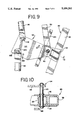
- FIG. 8 is an end view of the support mechanism illustrated in FIG. 6;
- FIG. 9 is an enlarged plan view of a lost motion mechanism of the present invention.
- FIG. 10 is a sectional view taken along line 7--7 of FIG. 6;
- FIG. 11 is a schematic diagram illustrating adjustment of the plow assembly according to the present invention.
- a plow assembly 10 adapted for connection to and pulled behind an agricultural implement such as tractor 12.
- the tractor 12 has tandum rear wheels 14 powered sufficiently to pull the plow assembly 10 across the field, and has a steering mechanism enabling the tractor to turn in either direction. It is conventional to provide such a tractor with articulated steering to enable the tractor to make relatively tight turns of a relatively short radius.
- the plow assembly 10 includes a plurality of conventional plow units generally designated by reference numeral 16. Although five plow units are shown, it should be appreciated that a greater number of plow units can be used in conjunction with the plow assembly without detracting or departing from the spirit and scope of the present invention.
- Each plow unit includes a ground engaging element 18 such as a moldboard which is capable of producing a furrow when properly positioned and the plow assembly is pulled along by the agricultural implement.
- a preferred form of plow assembly further includes a main frame 20, support assemblies 22 and 24 arranged at opposite ends of and supporting the main frame 20, and a mechanism 26 for steering the plow assembly relative to the tractor.
- the main frame 20 includes an elongated member 30 extending generally in the direction of tractor travel and a horizontally elongated beam 32 which is inclined relative to the direction of travel of the plow assembly.
- a forward end of member 30 is connected to the tractor 12 through a hitch assembly 34.
- a rear end of member 30 is fixedly connected proximate midlength of beam 32.
- a bracket 36 is used to connect and facilitate support of beam 32 to and from member 30.
- the plow units 16 are individually connected to and along the length of beam 32 at equally spaced intervals.
- the hitch assembly 34 includes a horizontal generally rectangular bar 38 connected at opposite ends to a conventional hitch mechanism generally designated 40 provided at a rear end of the tractor such that when the tractor turns, the bar 38 turns through the same steering angle as the tractor.
- a coupling 42 is provided proximate midlength of the bar 38. As shown in FIGS. 3 and 5, the coupling 42 is affixed to the bar 34 such that the bar 38 can rotate about a fore-and-aft generally horizontal axis 44 defined by an elongated bolt 46.
- Coupling 42 further includes a generally vertical shaft or spindle 48 which defines a generally vertical axis 50 about which the main frame is connected for rotation to the tractor.
- the plow assembly of the present invention further includes limit stops 52 and 54 for limiting angular movement of the main frame 20 when connected to and relative to the tractor.
- the limit stops 52 and 54 extend outwardly from opposite sides of the elongated member 30 and define stopping surfaces 56 and 58, respectfully.
- each stopping surface 56, 58 is adapted to abut against the hitch assembly 34 when the main frame has reached the limit of angular movement relative to the tractor.
- the limit stop 52 allows approximately 45 to 60 degrees of angular movement between the main frame and tractor in one direction of turning while limit stop 54 permits about 60 to 75 degrees of angular movement between the main frame and the tractor in an opposite direction of tractor turning movement.
- the support assembly 22 is articulately connected to and supports a rear end of the main frame 20.
- Support assembly 22 includes a frame 60 which carries a steering wheel 62 for generally vertical movement relative to the main frame 20 and for angular movement about a generally vertical axis 64 (FIGS. 6 and 8).
- steering wheel 62 is located in a manner to always follow in the furrow formed by the rearmost plow unit 16 on the main frame 20 during plowing.
- frame 60 is configured as a parallelogram assembly including a forward frame member 66 and a rear frame member 68 which are joined by vertically spaced and parallel links 70 and 72 pivotally connected at opposite ends to members 66 and 68.
- the forward frame member 66 is pivotally connected at 67 (FIG. 7) to the elongated inclined beam 32 of main frame 20.
- the rear frame member 66 is configured with a vertical sleeve which rotatably accommodates a vertical axle or support 74 for the steering wheel 62.
- the support assembly 22 is further provided with a driver 78 for selectively and vertically moving the steering wheel 62 relative to the main frame 20 thereby influencing the position of the main frame 20 and the plow units carried thereby relative to a ground surface over which the plow assembly moves.
- the tractor hitch mechanism 40 is vertically operated concurrently with driver 78 and in a conventional manner to maintain the plow assembly in a generally level condition.
- the driver 78 includes power actuated means such as a hydraulic cylinder or motor having one end connected to the forward frame member 66 of frame 60 and an opposite end connected to link 72 of the parallelogram linkage assembly.
- support assembly 22 further includes a land wheel 80.
- Land wheel 80 is carried on the support assembly 22 as by a vertically adjustable support 82 which regulates the vertical disposition of wheel 80 relative to the main frame 20.
- the land wheel 80 engages the ground surface during plowing and limits the working depth of the plow units and thereby the depth of the furrows.
- support assembly 24 at the forward end of the main frame 20 promotes relatively large turning angles (in excess of 35°) of the tractor relative to the direction of travel of the plow assembly by providing vertical support for the forward end of the main frame 20.
- support assembly 24 includes a frame 84 which carries a free-turning caster wheel 86 for generally vertical movement relative to the main frame 20.
- frame 84 is substantially identical in construction to frame 60 of support assembly 22. That is, frame 84 is designed as a parallelogram assembly which is joined to the forward end of beam 32 of the main frame 20 and provides free turning support for the ground engaging caster wheel 86.
- support assembly 24 further includes a driver 88 for selectively moving the caster wheel 86 in a vertical direction relative to the main frame thereby influencing the vertical disposition of the main frame 20 and the plow units 16 connected thereto.
- a salient feature of the present invention concerns the steering mechanism 26.
- the steering mechanism 26 normally holds the steering wheel 62 generally parallel to the furrows produced by the plow units as the plow assembly is moved across the field.
- the steering mechanism 26 has been designed to reduce the turning angle of the steering wheel 62 relative to the steering angle of the tractor thereby allowing the steering angle of the tractor to exceed 35° relative to the direction of travel of the plow assembly while facilitating turning of the plow assembly behind the tractor as the tractor turns at the end of a plowing operation.
- the steering mechanism 26 includes a linkage mechanism or assembly comprised of a first driver 90, a second driver 92, and mechanism 94 connected to and between the first and second drivers 90 and 92, respectively, for proportionately reducing the motion imparted therebetween.
- a first tie rod 96 connects driver 90 to mechanism 94
- a second tie rod 98 connects the mechanism 94 to driver 92.
- Driver 92 is connected as by a third tie rod 100 to the steering wheel 62 to control the angular disposition of the wheel.
- Driver 90 is preferably configured as a rotatable arm that responds to the turning angle of the tractor. As shown in FIGS. 3, 4, and 5, driver 90 is affixed to and for rotation with coupling 42 and is rotatable about the generally vertical axis 50 defined by spindle 48". A forward end of tie rod 96 is articulately connected to the driver 90. The distance separating the vertical axis 50 of shaft 48 from the point of connection of driver 90 to tie rod 96 measures the "effective length" of driver 90. Notably, driver 90 moves through an angle corresponding in magnitude to the turning angle of the tractor.
- Driver 92 is preferably configured as an arm that is rotatably mounted to the support assembly 22. As shown in FIGS. 6 and 7, an upright shaft 102, arranged in laterally spaced relation to pivot 67, rotatably mounts the driver arm 92 to the forward frame 66 of support assembly 22. In the embodiment illustrated, the lateral offset relation between shaft 102 and pivot 67 allows sufficient clearance of arm 92 relative to vertical displacement of trip linkage mechanisms (not shown) associated with the plow units. Preferably, shaft 102 and pivot 67 would be axially aligned. A rear end of tie rod 98 articulately connects driver 92 to the mechanism 94.
- the third tie rod 100 extends from driver 92 and is connected to an outboard end of a link or arm 104. Link 104 is secured toward an upper end of the vertical axle 74 adapted to turn or steer the steering wheel 62.
- the main frame 20 has elongated member 30 connected proximate midlength and to the elongated beam 32.
- member 30 is welded or otherwise fixedly secured to beam 32.
- mechanism 94 is preferably provided at the connection between member 30 and beam 32.
- a vertical shaft 110 rotatably passes through cantilevered brackets 112 which embrace member 30 and are affixed to beam 32.
- a cantilevered steering member 114 is rigidly attached to the top of shaft 110 for rotation about the longitudinal axis thereof.
- a first quadrilateral formation is established by the pivotal axes of the connections between the rod 96 with steering member 114 and arm 90, arm 90 with elongated member 30 of the main frame 20, and the vertical shaft 110 pivotally connecting steering member 114 to beam 32.
- the steering member 114 has the first tie rod 96 connected thereto as at 118.
- the free end of the steering member 114 is configured so as to allow the second tie rod 98 to likewise be connected as at 120.
- the location of connections 118 and 120 relative to the shaft 110 measure the "effective length" of the steering member 114.
- a second quadrilateral formation is established by the pivotal axes of the connections between the rod 98 with steering member 114 and arm 92, arm 92 with beam 32, and the vertical shaft 110 pivotally connecting steering member 114 to beam 32.
- the effective length of steering member 114 is greater than the effective length of either the first or second arms 90 or 92, respectively.
- steering member 114 is preferably provided with a series of apertures 122 which facilitate connection of tie rod 98 at different radial distances from the pivotal axis of the steering member 114.
- the different connection points on the steering member 114 permit modification of the effective length of the rotatable steering member 114 and thus configuring at least one of the quadrilateral formations into a non-parallelogram configuration thereby allowing the motion imparted between arms 90 and 92 to be proportionately reduced.
- the adjustability added by aperture 122 allows the magnitude of turning movement imparted to the steering wheel 62 in response to the tractor turning can be modified within a predetermined range.
- the series of apertures 122 are shown associated with the steering member 114 and the rod 98, it will be apparent to those skilled in the art that the adjustability of the linkage 26 can be otherwise provided otherwise without departing from the spirit and scope of the present invention.
- Another salient feature of the present invention concerns adjusting the plow units 16 through a predetermined range of motion thereby modifying the spacing between adjacent furrows as a function independent of the steering motion imparted to steering wheel 62 as through steering mechanism 26.
- the plow units 16 are attached to the inclined beam 32 in equally spaced relation to each other.
- each plow unit 16 is individually attached to the elongated beam 32 for rotation about a generally vertical axis.
- each plow unit 16 further includes an attachment mechanism permitting attachment of the plow unit to beam 32 and including a flange 124 which horizontally extends to one side of the inclined beam 32.
- a free end of each flange 124 is articulately connected to an elongated bar 126 which extends generally parallel to beam 32.
- bar 126 is likewise connected to frame member 66 of rear support assembly at a point radially spaced from pivot 67.
- bar 126 is movable generally parallel to the beam 32 under the influence of a driver assembly 130.
- the driver assembly includes power actuated means 132 in the form of a hydraulic cylinder having one end connected to member 30 and an opposite end connected through conventional linkage 133 to bar 126.
- the support assemblies 22 and 24 support the main frame 20 and generally control the disposition of the plow units 16 relative to the ground surface as a function of fluid flow to drivers 78 and 88.
- operation of the hitch mechanism 40 promotes levelness of the main frame 20 during operation.
- the land wheel 80 will substantially control the depth of the furrows.
- the steering wheel 62 will ride in the furrow formed by the rearmost plow unit.
- the steering mechanism 26 maintains the steering wheel 62 generally parallel to the wheels on the tractor as the power assembly is pulled along a relatively straight line path.
- the steering mechanism 26 When the tractor is turned relative to the direction of travel of the plow assembly, the steering mechanism 26 will turn the steering wheel 62 through an angle which is opposite to the steering angle of the tractor to thereby swing the plow assembly behind the tractor.
- One advantage of the present invention is that the steering mechanism 26 allows the tractor to be turned through a tight turn radius, i.e., the tractor can be turned through a steering angle in excess of 35° relative to the direction of travel of the plow assembly.
- the forward support assembly 24 promotes support of the forward end of the main frame 20 thereby allowing such tight turns.
- driver 90 of steering mechanism 26 turns through a corresponding angle to that of the steering angle of the tractor.
- movement imparted by driver 90 will be in excess of that required to move the steering wheel 62.
- Mechanism 94 acts as a lost motion device and advantageously proportions the movement of the driver 90 and steers wheel 62 through an angle which is reduced relative to the steering angle of the tractor. Accordingly, the tractor can effect relatively tight turns with the plow assembly turned therebehind. Stops 52 and 54 limit the angular movement of the plow assembly relative to the tractor.
- Mechanism 94 of the steering mechanism further allows customization of the steering mechanism to the particular plowing operation being performed.
- the effective lengths of arms 90, 92, and 114 relative to each other will regulate the steering angle of the wheel 62 relative to the turning angle of the tractor and thereby regulate turning action of the plow assembly relative to the tractor.
- the ability to vary the effective length of steering member 114 of mechanism 94 will, of course, allow operation of the steering mechanism to be modified to suit a particular plowing operation.
- Still another advantage of the present invention is the ability to adjust spacing between adjacent furrows as the plow assembly is being pulled behind the tractor.
- the cylinder 132 of driver assembly 130 is preferably a double-acting cylinder which allows positive translation of the bar 126 in opposite directions thereby forcibly rotating the plow units 16 about their respective vertical axes in either angular direction.
- retraction of the cylinder 132 "closes” the plow units relative to each other such that the lateral spacing between adjacent furrows becomes closer while extension of the cylinder 132 "opens" the plow units 16 relative to each other thereby resulting in an increase in the spacing between adjacent furrows produced by the plow units.
- lines 16a represent the cutting lines of plow units arranged on the elongated beam 32 of the main frame 20 shown in solid lines.
- mounting the plow units for rotation about individual axes tends to straighten the respective plow unit as it is pulled through the ground in a manner similar to a rudder acting on a ship.
- the drive assembly 130 is operated.
- the cylinder 132 of driver assembly 130 is retracted thereby altering the cut lines provided by the plow units and thereby shifting the inclination of the elongated beam to the position illustrated in dotted lines in FIG. 11.
- a change in the inclination of the beam 32 modifies or alters the spacing between adjacent furrows while maintaining the spacing of the plow units relative to the beam.
- the drive assembly 132 holds the beam 32 in the desired position while all of the plow units tend to self straighten.
- the lateral spacing between adjacent units is modified as shown by cut lines 16b in FIG. 11.
- the lateral spacing between adjacent plow units remains constant thereby achieving continuity in the furrow spacing.
- one end of the elongated bar 126 is secured to the forward frame member 66 of the rear support assembly 22.
- the drive assembly 130 When the drive assembly 130 is activated, movement of the bar 126 will cause rotation of the frame member 66 of support assembly 22 about the pivot shaft 67. Accordingly, upon shifting of the plow units, the steering wheel 62 is shifted therewith and will always ride in the furrow formed by the rearmost plow unit. Notably, however, the action of the drive assembly 130 on the steering wheel 62 is independent of that provided by the steering mechanism 26 relative to the steering wheel 62.
Abstract
Description
Claims (15)
Priority Applications (1)
| Application Number | Priority Date | Filing Date | Title |
|---|---|---|---|
| US07/720,651 US5186261A (en) | 1991-06-25 | 1991-06-25 | On-land plow assembly with a plurality of adjustable plow units |
Applications Claiming Priority (1)
| Application Number | Priority Date | Filing Date | Title |
|---|---|---|---|
| US07/720,651 US5186261A (en) | 1991-06-25 | 1991-06-25 | On-land plow assembly with a plurality of adjustable plow units |
Publications (1)
| Publication Number | Publication Date |
|---|---|
| US5186261A true US5186261A (en) | 1993-02-16 |
Family
ID=24894802
Family Applications (1)
| Application Number | Title | Priority Date | Filing Date |
|---|---|---|---|
| US07/720,651 Expired - Lifetime US5186261A (en) | 1991-06-25 | 1991-06-25 | On-land plow assembly with a plurality of adjustable plow units |
Country Status (1)
| Country | Link |
|---|---|
| US (1) | US5186261A (en) |
Cited By (3)
| Publication number | Priority date | Publication date | Assignee | Title |
|---|---|---|---|---|
| FR2748628A1 (en) * | 1996-05-14 | 1997-11-21 | Berger F & C | DEVICE FOR FASTENING A PLOW BODY ON THE PLOW FRAME |
| GB2302493B (en) * | 1995-06-22 | 1999-03-03 | Kverneland Klepp As | Single furrow plough |
| CN102900109A (en) * | 2012-09-21 | 2013-01-30 | 三一重工股份有限公司 | Land leveler and scarifier thereof |
Citations (10)
| Publication number | Priority date | Publication date | Assignee | Title |
|---|---|---|---|---|
| US3503453A (en) * | 1967-12-11 | 1970-03-31 | Deere & Co | Semi-integral reversible disk plow with steerable transport wheel |
| US3583494A (en) * | 1967-08-31 | 1971-06-08 | Massey Ferguson Inc | Weight transfer hitch for plows |
| US3603405A (en) * | 1970-01-07 | 1971-09-07 | Deere & Co | Device for automatically landing a semi-integral moldboard plow |
| US3750759A (en) * | 1967-09-07 | 1973-08-07 | C Geurts | Hitch construction |
| US3817333A (en) * | 1972-02-16 | 1974-06-18 | Dietrich Mfg Inc | Plow system with plurality of plow units and means for adjusting spacing between units in a continuous manner |
| US3918528A (en) * | 1972-02-16 | 1975-11-11 | Dmi | Plow system with plurality of plow units and means for adjusting spacing between units in a continuous manner |
| US4077651A (en) * | 1976-10-01 | 1978-03-07 | Deere & Company | Hydraulic steering for plow |
| US4186806A (en) * | 1977-09-06 | 1980-02-05 | International Harvester Company | Plow system |
| US4475601A (en) * | 1982-09-20 | 1984-10-09 | International Harvester Co. | Variable width plow system with shim means adjustment |
| US4502544A (en) * | 1982-05-10 | 1985-03-05 | Kverneland A/S | Plow assembly with turn limiter |
-
1991
- 1991-06-25 US US07/720,651 patent/US5186261A/en not_active Expired - Lifetime
Patent Citations (10)
| Publication number | Priority date | Publication date | Assignee | Title |
|---|---|---|---|---|
| US3583494A (en) * | 1967-08-31 | 1971-06-08 | Massey Ferguson Inc | Weight transfer hitch for plows |
| US3750759A (en) * | 1967-09-07 | 1973-08-07 | C Geurts | Hitch construction |
| US3503453A (en) * | 1967-12-11 | 1970-03-31 | Deere & Co | Semi-integral reversible disk plow with steerable transport wheel |
| US3603405A (en) * | 1970-01-07 | 1971-09-07 | Deere & Co | Device for automatically landing a semi-integral moldboard plow |
| US3817333A (en) * | 1972-02-16 | 1974-06-18 | Dietrich Mfg Inc | Plow system with plurality of plow units and means for adjusting spacing between units in a continuous manner |
| US3918528A (en) * | 1972-02-16 | 1975-11-11 | Dmi | Plow system with plurality of plow units and means for adjusting spacing between units in a continuous manner |
| US4077651A (en) * | 1976-10-01 | 1978-03-07 | Deere & Company | Hydraulic steering for plow |
| US4186806A (en) * | 1977-09-06 | 1980-02-05 | International Harvester Company | Plow system |
| US4502544A (en) * | 1982-05-10 | 1985-03-05 | Kverneland A/S | Plow assembly with turn limiter |
| US4475601A (en) * | 1982-09-20 | 1984-10-09 | International Harvester Co. | Variable width plow system with shim means adjustment |
Cited By (4)
| Publication number | Priority date | Publication date | Assignee | Title |
|---|---|---|---|---|
| GB2302493B (en) * | 1995-06-22 | 1999-03-03 | Kverneland Klepp As | Single furrow plough |
| FR2748628A1 (en) * | 1996-05-14 | 1997-11-21 | Berger F & C | DEVICE FOR FASTENING A PLOW BODY ON THE PLOW FRAME |
| CN102900109A (en) * | 2012-09-21 | 2013-01-30 | 三一重工股份有限公司 | Land leveler and scarifier thereof |
| CN102900109B (en) * | 2012-09-21 | 2016-07-13 | 三一重工股份有限公司 | Land leveller and ridge buster thereof |
Similar Documents
| Publication | Publication Date | Title |
|---|---|---|
| US4186806A (en) | Plow system | |
| US4184551A (en) | Steering device for row crop cultivator | |
| US5878821A (en) | Tillage implement with on-the-go angle and depth controlled discs | |
| US3583494A (en) | Weight transfer hitch for plows | |
| US6263977B1 (en) | Winged agricultural implement with headlands control system | |
| US4402367A (en) | Folding tool beam and lift assembly | |
| US4502544A (en) | Plow assembly with turn limiter | |
| US4564073A (en) | Plow or harrow | |
| US4535849A (en) | Implement with horizontal linkage depth control | |
| US3817333A (en) | Plow system with plurality of plow units and means for adjusting spacing between units in a continuous manner | |
| US4036305A (en) | Gang plow | |
| US5303779A (en) | Rockshaft cultivator frame | |
| US4036306A (en) | Multi-unit adjustable plow pulled by vehicle and having steering wheel turnable only on adjustment of plow | |
| US3918528A (en) | Plow system with plurality of plow units and means for adjusting spacing between units in a continuous manner | |
| US4049063A (en) | Multi-unit adjustable plow system | |
| US4502545A (en) | Folding tool beam and lift assembly | |
| US5186261A (en) | On-land plow assembly with a plurality of adjustable plow units | |
| CA1087440A (en) | Plow mounting bracket | |
| US2713296A (en) | Semi-integral disk plow | |
| US3481406A (en) | Semintegral two-way plow with offset steerable tail wheel | |
| US4475601A (en) | Variable width plow system with shim means adjustment | |
| US4282935A (en) | Multiple section, adjustable width plow | |
| US3387862A (en) | Tractor hitch with sway limiting mechanism | |
| US4487267A (en) | Agricultural apparatus with tool supported thereon and wheel adjustment structure therefor | |
| US4271913A (en) | Articulated plow with horizontal angularity between its frames |
Legal Events
| Date | Code | Title | Description |
|---|---|---|---|
| AS | Assignment |
Owner name: CASE CORPORATION, A CORPORATION OF DE Free format text: ASSIGNMENT OF ASSIGNORS INTEREST.;ASSIGNOR:WILL, JOHN H.;REEL/FRAME:005777/0923 Effective date: 19910611 Owner name: CASE CORPORATION, A CORPORATION OF DE Free format text: ASSIGNMENT OF ASSIGNORS INTEREST.;ASSIGNOR:GRIMM, WILLIAM L.;REEL/FRAME:005777/0925 Effective date: 19910614 |
|
| AS | Assignment |
Owner name: SUNDSTRAND CORPORATION, ILLINOIS Free format text: ASSIGNMENT OF ASSIGNORS INTEREST.;ASSIGNOR:WESTINGHOUSE ELECTRIC CORPORATION A CORP. OF PENNSYLVANIA;REEL/FRAME:006208/0802 Effective date: 19920615 |
|
| STCF | Information on status: patent grant |
Free format text: PATENTED CASE |
|
| AS | Assignment |
Owner name: CASE EQUIPMENT CORPORATION, WISCONSIN Free format text: ASSIGNMENT OF ASSIGNORS INTEREST;ASSIGNOR:CASE CORPORATION;REEL/FRAME:007125/0717 Effective date: 19940623 |
|
| AS | Assignment |
Owner name: CASE CORPORATION, WISCONSIN Free format text: CHANGE OF NAME;ASSIGNOR:CASE EQUIPMENT CORPORATION;REEL/FRAME:007132/0468 Effective date: 19940701 |
|
| FPAY | Fee payment |
Year of fee payment: 4 |
|
| FPAY | Fee payment |
Year of fee payment: 8 |
|
| FPAY | Fee payment |
Year of fee payment: 12 |
|
| AS | Assignment |
Owner name: CNH AMERICA LLC, PENNSYLVANIA Free format text: ASSIGNMENT OF ASSIGNORS INTEREST;ASSIGNOR:CASE CORPORATION;REEL/FRAME:014981/0944 Effective date: 20040805 |
|
| AS | Assignment |
Owner name: BLUE LEAF I.P., INC., DELAWARE Free format text: ASSIGNMENT OF ASSIGNORS INTEREST;ASSIGNOR:CNH AMERICA LLC;REEL/FRAME:017766/0484 Effective date: 20060606 Owner name: CNH AMERICA LLC, PENNSYLVANIA Free format text: ASSIGNMENT OF ASSIGNORS INTEREST;ASSIGNOR:CNH AMERICA LLC;REEL/FRAME:017766/0484 Effective date: 20060606 |