US518480A - Clover-feeder - Google Patents
Clover-feeder Download PDFInfo
- Publication number
- US518480A US518480A US518480DA US518480A US 518480 A US518480 A US 518480A US 518480D A US518480D A US 518480DA US 518480 A US518480 A US 518480A
- Authority
- US
- United States
- Prior art keywords
- clover
- cranks
- feed
- bars
- feeding
- Prior art date
- Legal status (The legal status is an assumption and is not a legal conclusion. Google has not performed a legal analysis and makes no representation as to the accuracy of the status listed.)
- Expired - Lifetime
Links
- 241000219793 Trifolium Species 0.000 description 11
- 238000010276 construction Methods 0.000 description 3
- 230000005484 gravity Effects 0.000 description 1
Images
Classifications
-
- A—HUMAN NECESSITIES
- A01—AGRICULTURE; FORESTRY; ANIMAL HUSBANDRY; HUNTING; TRAPPING; FISHING
- A01F—PROCESSING OF HARVESTED PRODUCE; HAY OR STRAW PRESSES; DEVICES FOR STORING AGRICULTURAL OR HORTICULTURAL PRODUCE
- A01F12/00—Parts or details of threshing apparatus
- A01F12/10—Feeders
- A01F12/12—Feeders without band-cutters
Definitions
- NrTnD STATES WILLIAM E. AYERS, OF OOLLTT, INDIANA.
- Object of my invention is the provision of a feeding mechanism which can be attached to the ordinary clover hulling machine at a comparatively small expense and which will feed the clover smoothly, evenly and rapidly to the hulling cylinder.
- the invention consists of a trough or receptacle adapted to be attached adjacent to the feeding apron and the hulling cylinder and having mounted therein shafts provided with reversely arranged cranks and feeding bars arranged on or secured to said cranks whereby they alternately in sets move the clover to the cylinder; and the invention also consists in certain improvements in the construction, combination and arrangement of parts for service as disclosed herein.
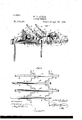
- Figure l represents a perspective view of a portion of a clover hulling machine and my feeding mechanism in connection therewith to fully illustrate the arrangement of the feeder
- Fig. 2 represents a plan View on an enlarged scale of the feeding mechanism detached.
- the numeral designates the rear portion of a clover hulling machine; 2 designates the trough or receptacle or chute leading to the cylinder of the machine; and 3 designates the frame in which is mounted the feeding apron or belt 4, all of which parts are of the Well known construction and upon which I lay no claim broadly.
- the shafts 5 having an upper set of cranks 6 and alower set of cranks 7, in this instance there being two cranks in each set although more may be used if desired, and these cranks are rotated by means of the pulleys 8 and belt 9,
- Fig. l the free hinged sections 13 are shown in full lines and in dotted lines.
- the said free ends are adapted by gravity to descend and take the clover from the apron and carry it to the feed chute and this is an important feature as it is simply necessary to place the clover upon the apron and the free hinged sections will reach and take it and carry it to the feed chute.
Landscapes
- Life Sciences & Earth Sciences (AREA)
- Environmental Sciences (AREA)
- Preliminary Treatment Of Fibers (AREA)
Description
(No Model.)
W. E. A'YBRS.
GLOVBR FEEDER. No. 518,480. Pahented Apr. 17, 1894.
I3 6 ljfrveese.'
fr f' r .l a r Wm@ l I f I y THE NATIONAL LITNOGRAPHIN OMPANV.
mmc.
NrTnD STATES WILLIAM E. AYERS, OF OOLLTT, INDIANA.
Aram* ritten.,
SPECIFICATION forming part of Letters Patent No. 518,480, dated April 17, 1894.
Application filed August 31,1893. Serial No. 484-526. (No model.)
To @ZZ whom, it may concern:
Be it known that I, WILLIAM E. AYERs, a citizen of the United States, residing at Collett, in the county of Jay and State of Indiana, haveinvented certain newand usefullmprovements in Clover-Feeders; and I do declare the following to be a full, clear, and exact description of the in vent-ion, such as will enable others skilled in the art to which it appertains to make and use the same, reference be ing had to the accompanying drawings, and to the letters of reference marked thereon,
which form a part of this specification.
. Object of my invention is the provision of a feeding mechanism which can be attached to the ordinary clover hulling machine at a comparatively small expense and which will feed the clover smoothly, evenly and rapidly to the hulling cylinder.
To attain the desired object the invention consists ofa trough or receptacle adapted to be attached adjacent to the feeding apron and the hulling cylinder and having mounted therein shafts provided with reversely arranged cranks and feeding bars arranged on or secured to said cranks whereby they alternately in sets move the clover to the cylinder; and the invention also consists in certain improvements in the construction, combination and arrangement of parts for service as disclosed herein.
Figure l represents a perspective view of a portion of a clover hulling machine and my feeding mechanism in connection therewith to fully illustrate the arrangement of the feeder, Fig. 2 represents a plan View on an enlarged scale of the feeding mechanism detached.
Referring by numerals to the drawings- The numeral] designates the rear portion of a clover hulling machine; 2 designates the trough or receptacle or chute leading to the cylinder of the machine; and 3 designates the frame in which is mounted the feeding apron or belt 4, all of which parts are of the Well known construction and upon which I lay no claim broadly.
In the trough or chute 2 is mounted the shafts 5 having an upper set of cranks 6 and alower set of cranks 7, in this instance there being two cranks in each set although more may be used if desired, and these cranks are rotated by means of the pulleys 8 and belt 9,
driven from a suit-able source. From this construction it will be seen that one set of cranks moves inward while the other moves outward, or one set moves inward and the other outward alternately so that a constant feed is insured. To one set of cranks is connected the feed bars l0 and to the other set is connected the feed bars l0 and Asaid bars carry the teeth or arms l2 and have the hinged or jointed end sections 13 which en able the bars to conform to the shape of the feed apron or rather to the relation of it to the feed chute.
The operation of my feeder will be readily understood from the foregoing description taken'in connection with the accompanying drawings and I will simply state that the clover is first placed upon the endless apron from which it is carried by the outer hinged free sections of the feed bars into the feed chute and is there taken by the feed bars and moved or fed into the huller Where it is acted upon by the hulling cylinder or other means according to the nature of the machine. It will be seen that the feed is positive, even and rapid and that while one set of bars is feeding the clover the other set is getting into operative position.
In the drawings, Fig. l, the free hinged sections 13 are shown in full lines and in dotted lines. The said free ends are adapted by gravity to descend and take the clover from the apron and carry it to the feed chute and this is an important feature as it is simply necessary to place the clover upon the apron and the free hinged sections will reach and take it and carry it to the feed chute. The
sections are hinged so as to descend the deabove the feeding apron and descend to take sired distance to take the clover properly. the clover from said apron. y
claim- In testimony whereof I afx my signature in The combination of the frame, the feeding presence of two Witnesses. 5- apron traveling therein, the trough adjacent his to the frame,the shafts mounted in the trough VILLIAM E. AYERS. and having two sets of reversely arranged mark cranks, mechanism for rotating the shafts, Witnesses: the feeding bars having teeth and secured to S. K. POLING, 1o the cranks, and hinged sections at the outer l A. W. EVILSIZER.
end of the feeding bars, adapted to move
Publications (1)
| Publication Number | Publication Date |
|---|---|
| US518480A true US518480A (en) | 1894-04-17 |
Family
ID=2587281
Family Applications (1)
| Application Number | Title | Priority Date | Filing Date |
|---|---|---|---|
| US518480D Expired - Lifetime US518480A (en) | Clover-feeder |
Country Status (1)
| Country | Link |
|---|---|
| US (1) | US518480A (en) |
-
0
- US US518480D patent/US518480A/en not_active Expired - Lifetime
Similar Documents
| Publication | Publication Date | Title |
|---|---|---|
| US518480A (en) | Clover-feeder | |
| US584889A (en) | Corn-husker | |
| US153956A (en) | Improvement in grain-separators | |
| US265769A (en) | Feeder for thrashing-machines | |
| US277488A (en) | Machine for assorting horseshoe-nails | |
| US635480A (en) | Grain-scourer. | |
| US380389A (en) | Epheaim hebbingtoe | |
| US397879A (en) | Portable corn thrasher and separator | |
| US58986A (en) | Improvement in corn-shellers | |
| US335988A (en) | Cornelius w | |
| US400217A (en) | Thrashing-machine | |
| US176908A (en) | Improvement in cotton-gin feeders | |
| US132969A (en) | Improvement | |
| US1112194A (en) | Thresher. | |
| US71093A (en) | Improvement in threshing machines | |
| US139355A (en) | Improvement in thrashing-machines | |
| US141526A (en) | Improvement in thrashing-machines | |
| US526869A (en) | Wawinctok | |
| US160342A (en) | Improvement in corn-shellers | |
| US978570A (en) | Threshing-machine. | |
| US644157A (en) | Threshing-machine. | |
| US223906A (en) | Territoby | |
| US418768A (en) | Thrashing-machine | |
| US1233529A (en) | Feed-hopper for flax-working machines. | |
| US1019185A (en) | Feeder and grit-separator. |