US5184802A - Wire grid for box spring bedding assembly - Google Patents
Wire grid for box spring bedding assembly Download PDFInfo
- Publication number
- US5184802A US5184802A US07/627,030 US62703090A US5184802A US 5184802 A US5184802 A US 5184802A US 62703090 A US62703090 A US 62703090A US 5184802 A US5184802 A US 5184802A
- Authority
- US
- United States
- Prior art keywords
- grid
- box spring
- wires
- wire
- differing
- Prior art date
- Legal status (The legal status is an assumption and is not a legal conclusion. Google has not performed a legal analysis and makes no representation as to the accuracy of the status listed.)
- Expired - Lifetime
Links
- 230000000712 assembly Effects 0.000 claims abstract description 23
- 238000000429 assembly Methods 0.000 claims abstract description 23
- 238000003491 array Methods 0.000 claims abstract description 10
- 238000012986 modification Methods 0.000 claims abstract description 8
- 230000004048 modification Effects 0.000 claims abstract description 8
- 238000010276 construction Methods 0.000 abstract description 17
- 239000002023 wood Substances 0.000 description 3
- 230000006978 adaptation Effects 0.000 description 2
- 238000004519 manufacturing process Methods 0.000 description 2
- 230000003466 anti-cipated effect Effects 0.000 description 1
- 239000004744 fabric Substances 0.000 description 1
- 230000000087 stabilizing effect Effects 0.000 description 1
- 239000000126 substance Substances 0.000 description 1
Images


Classifications
-
- A—HUMAN NECESSITIES
- A47—FURNITURE; DOMESTIC ARTICLES OR APPLIANCES; COFFEE MILLS; SPICE MILLS; SUCTION CLEANERS IN GENERAL
- A47C—CHAIRS; SOFAS; BEDS
- A47C23/00—Spring mattresses with rigid frame or forming part of the bedstead, e.g. box springs; Divan bases; Slatted bed bases
- A47C23/04—Spring mattresses with rigid frame or forming part of the bedstead, e.g. box springs; Divan bases; Slatted bed bases using springs in compression, e.g. coiled
- A47C23/05—Frames therefor; Connecting the springs to the frame ; Interconnection of springs, e.g. in spring units
Definitions
- the present invention relates generally to box spring bedding assemblies of the type adapted for use as a mattress foundation and, more particularly, to a wire grid for use in such a box spring bedding assembly to support an array of coil springs.
- Conventional box spring bedding assemblies are of a relatively common uniform construction having a rectangular base frame on which a spaced array of multiple coil springs are mounted in upstanding disposition in a spaced array, with a correspondingly rectangular wire grid connected to a top coil of each spring, the entire construction being upholstered with a suitable fabric or other appropriate covering.
- the base frame is fabricated of wood, having a rectangular outer sub-frame with a longitudinal frame member extending the length of the sub-frame midway across its width and with a plurality of lateral frame members, commonly referred to as slats, extending widthwise across the sub-frame in parallel relation to one other at spacings along the length of the sub-frame.
- the plural coil springs of the box spring assembly are arrayed in widthwise-extending parallel rows across the lateral slats and the laterally-extending end members of the sub-frame.
- box spring assemblies of this basic construction have traditionally been manufactured in varying grades, differentiated primarily according to the number of coil springs incorporated in the box spring assembly which correspondingly affects the overall firmness and anticipated useful life of the box spring assembly.
- a greater number of slats are provided in the base frame of box spring assemblies which are to incorporate a greater number of coil springs.
- box spring assemblies of a stand size commonly called “full size”
- many manufacturers produce box springs in three differing grades utilizing three differing base frame constructions each with a differing number of lateral slats (e.g., six, seven, or eight slats) in order to achieve differing arrays of differing numbers of coil springs for varied degrees of firmness.
- box spring assemblies in other sizes commonly referred to as “twin”, “queen”, and “king” (i.e, two “twin” box springs) sizes are also commonly produced in differing grades generally differentiated only by the number of slats and springs utilized in the box spring.
- each differing box spring construction requires a differing wire grid to interconnect the top coils of the particular array of coil springs, which does significantly increase the manufacturer's costs since such wire grids cannot be as easily and inexpensively manufactured in differing construction.
- wire grids are acquired by box spring manufacturers from a third party, necessitating that the manufacturer maintain separate inventories of each differing wire grid, whereas in contrast the box spring manufacturer would typically fabricate the base frames itself from stock pre-cut wooden frame members and slats which do not vary in size from one grade of box spring to another.
- the wire grid of the present invention basically comprises a plurality of relatively rigid longitudinal wires and a plurality of relatively rigid transverse wires, wherein the longitudinal wires are arranged in spaced parallel relation to one another and rigidly connected to the longitudinal wires in substantially perpendicular relation thereto, thereby to form the grid in an overall rectangular configuration.
- the transverse wires are further arranged to provide a plurality of possible groupings of adjacent wires spaced along the length of the grid, with the wires of each grouping being cooperative with one another for connection thereto of a plurality of coil springs laterally spaced across the width of the grid.
- the number of such groupings is sufficient to enable the grid to accept a plurality of differing arrays of coil springs utilizing varying combinations of the wire groupings for use of the grid without modification in varying box spring assemblies.
- the wire groupings are arranged relative to one another for use of the wire grid with a plurality of differing box spring frames having differing numbers of widthwise-extending slats at differing spacings from one another.
- the wire groupings are more closely spaced to one another in a central region along the length of the grid than in end regions at the opposite ends of the grid to permit a greater concentration of coil springs to be mounted in the central region.
- each wire grouping is arranged for interlocking engagement with an end coil of each coil spring connected thereto.
- each wire grouping may comprise a set of three adjacent wires for engagement of end coil of a coil spring at one side of the intermediate wire and at the opposite side of the other two wires, thereby to secure the coil spring to the wire groupings.
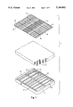
- FIG. 1 is an exploded perspective view of the internal components of a box spring bedding assembly incorporating a wire grid according to the preferred embodiment of the present invention
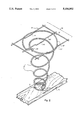
- FIG. 2 is an enlarged perspective view of one spring unit and a portion of the wire grid of the box spring bedding assembly of FIG. 1, illustrating the manner of assembly thereof;
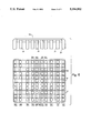
- FIGS. 3, 4, and 5 are schematic plan views respectively illustrating the various use of the present wire grid of FIG. 1 in box spring assemblies of differing constructions utilizing differing numbers of widthwise-extending slats.
- box spring assembly excluding any upholstering or outer covering, is shown in exploded form and broadly indicated at 10, the box spring assembly 10 basically including a rectangular base frame 12 on which an array of individual coil spring units 14 are supported in upstanding disposition with a correspondingly rectangular wire grid 16 according to the preferred embodiment of the present invention connected respectively to the top coils of the spring units 14.
- the base frame 12 is of a substantially conventional construction fabricated of wooden boards.
- the base frame 12 includes an outer rectangular sub-frame 18 formed of a spaced parallel pair of widthwise-extending end frame members 20 affixed at their respective ends in perpendicular end-to-end relation to a pair of spaced parallel lengthwise-extending side frame members 22.
- a plurality of widthwise-extending substantially flat support slats 24 are affixed at their respective ends to the side frame members 22 to extend therebetween in spaced parallel relation along the length thereof.
- An elongate stabilizing member 26 extends the length of the sub-frame 18 at substantially its widthwise midpoint and is affixed to the underside of each end frame member 20 and each slat 24, thereby to rigidify the sub-frame 18.
- the upper surfaces of the end frame members 20 and the slat 24 substantially lie in a common plane to provide weight-bearing surfaces for the coil spring units 14.
- the spring units 14 may be of substantially any conventional construction commonly utilized in box spring assemblies or any other suitable spring construction providing appropriate spring characteristics.
- the illustrated spring units 14 are representative of a common type of conventional coil-type spring unit utilized in many conventional box spring bedding assemblies.
- Each spring unit 14 is fabricated of a continuous length of resilient spring wire formed in a series of circular coils 28, the top coil 28' being relatively enlarged and closed by a knot tying the upper free end of the spring wire to the next adjacent coil 28, as indicated at 30, and the bottom coil 28" being open to leave the opposite bottom free end 32 of each spring wire exposed.
- each spring unit 14 may be rigidly secured in upstanding disposition on the sub-frame 18 by affixing the free end 32 of the bottom spring coil 28 to the upper support surface of one of the slats 24 or the end frame members 20 utilizing a staple, clip, or other suitable fastener 31.
- the top coils 28' of the spring units 14 substantially lie in a common plane.
- the grid 16 is formed of two sets of relatively rigid wires 34,36 welded or otherwise affixed to one another with the wires of each set in spaced parallel relation to one another and in substantially perpendicular relation to the wires of the other set. In this manner, the grid 16 is of an overall substantially rectangular configuration corresponding in widthwise and lengthwise dimensions to the rectangular base frame 12.
- the widthwise-extending grid wires 34 are arranged at sufficiently close spacings to one another to provide multiple groupings of three successively-adjacent wires 34, as representatively indicated at 38, which groupings 38 correspond in parallel spaced relation to one another lengthwise of the wire grid 16 to the spacing of the slats 24 and end frame members 20 of the base frame 12 to directly overlie the slats 24 and end frame members 20 for connection of the top coils 28' of the spring units 14 respectively to the wire groupings 38.
- the top coil 28' of each spring unit 14 is engaged with a respective grouping 38 of the grid wires 34 by disposition of the top coil 28' with a medial portion thereof extending over the intermediate wire 38' of the groupings 38 and with opposite lateral portions of the top coil 28' extending under the other two wires 38" of the grouping 38 at opposite sides of the intermediate wire 38'.
- the undersurface of the top coil 28' of each spring unit 14 may be formed with a notch 40, preferably generally diametrically opposite the wire knot 30 for engagement of the intermediate wire 38' in the notch 40 as well as between the top coil 28' and the next adjacent coil 28 of the spring unit 14 adjacent the knot 30 to rigidify the connection of the top coil 28' to the wire grouping 38.
- each grid wire 34 may be formed with downwardly extending segments 42 at corresponding locations for secure engagement of the segments 42 in each outer wire 38" of each wire grouping 38 with the lateral portions of the top coil 28' of each spring unit 14, to further rigidify the mounting of each top coil 28' to the grid 16.
- the wire grid 16 is constructed with its grid wires 34 spaced relative to one another to provide a sufficient number of possible groupings 38 each of three grid wires 34, to enable the grid 16 to be employed without modification in various box spring assemblies having base frames 12 of differing constructions, particularly differing grades of conventional box spring assemblies of differing grades utilizing differing numbers of support slats 24, as best seen and understood with reference to FIGS. 3-5.
- FIGS. 3-5 illustrate schematically conventional constructions of box spring base frames 12 commonly utilized in differing grades of standard full-size box spring assemblies, FIG. 3 illustrating a base frame 112 having six spaced slats 24 such as typically provided in many budget-grade standard full-size box spring assemblies, FIG.
- FIG. 4 illustrating a base frame 212 having seven slats 24 such as provided in medium grade standard full-size box spring assemblies
- FIG. 5 illustrating a base frame 312 having eight slats 24 representative of many premium-grade standard full-size box spring assemblies.
- the respective end frame members 20 and slats 24 thereof define, within the same rectangular dimensions of a standard full-size box spring assembly, a total of fifteen different locations for widthwise-extending rows of coil spring units 14; hence, the wire grid 16 of the present invention provides fifteen corresponding possible groupings 38 of grid wires 34, indicated in FIG. 3 at 38a through 38o.
- the respective slats 24 and end frame members 20 of the base frames 112 and 212 define together a total of eleven different locations for widthwise coil spring rows and the slats 24 and end frame members 20 of the base frames 212 and 312 define together a total of thirteen different widthwise coil spring row locations.
- a wire grid intended for interchangeable use with only the base frames 112 and 212 would need to provide only eleven corresponding wire groupings 38 and a wire grid interchangeably usable with only the base frames 212 and 312 would have to provide only thirteen corresponding wire groupings 38.
- the grid wires 34 are arranged to provide a closer spacing of the wire groupings 38 relative to one another than at the opposite ends of the grid 16 such that certain individual grid wires 34 may serve as part of two different wire groupings 38, thereby to permit a greater concentration of coil spring units 14 to be mounted in this central region of the grid 16 to accommodate the slat locations of each of the base frames 112, 212, 312.
- the wire groupings 38a, 38b, 38c, 38f, 38j, 38m, 38n, and 38o are employed to connect the top coils 28' of the spring units 14 mounted on the base frame 112, regardless of the particular array of the spring units 14.
- the wire groupings 38a, 38b, 38c, 38e, 38h, 38k, 38m, 38n, and 38o are employed to connect the spring units 14 to the grid 16.
- the wire groupings 38a, 38b, 38c, 38d, 38g, 38i, 38l, 38m, 38n, and 38o are employed to connect the spring units 14 to the grid 16.
- FIGS. 3-5 illustrate representative arrays of spring units 14 which are made possible by use of the present wire grid 16 in conjunction with the base frames 112, 212, 312, respectively, the particular locations of the spring units 14 in each Figure being only schematically indicated by blackened circles for sake of simplicity of illustration. However, it is to be understood that the illustrated arrays of spring units 14 are only exemplary many other spring arrays being possible with the present wire grid 16.
- FIG. 3 illustrates a box spring assembly wherein sixty coil spring units 14 are supported between the six-slat base frame 12 and the wire grid 16, it would be equally possible to provide a more limited array of only forty-eight coil spring units 14 arranged in eight widthwise-extending rows of six spring units each or, alternatively, a more extensive array of eighty-eight coil spring units 14 arranged in eight widthwise-extending rows of eleven spring units each, as well as other varying alternative arrays.
- FIG. 3 illustrates a box spring assembly wherein sixty coil spring units 14 are supported between the six-slat base frame 12 and the wire grid 16
- FIG. 3 illustrates a box spring assembly wherein sixty coil spring units 14 are supported between the six-slat base frame 12 and the wire grid 16
- FIG. 3 illustrates a box spring assembly wherein sixty coil spring units 14 are supported between the six-slat base frame 12 and the wire grid 16
- FIG. 3 illustrates a box spring assembly wherein sixty coil spring units 14 are supported between the six-slat base frame 12
- FIG. 4 illustrates a possible array of seventy-two coil spring units 14, it would be equally possible utilizing the grid 16 of the present invention to provide a more limited array of fifty-four coil spring units 14 arranged in nine widthwise-extending rows of six spring units each or a more extensive array of ninety-nine coil spring units 14 arranged in nine widthwise-extending rows of eleven spring units each.
- a more limited array of sixty coil spring units 14 could be arranged in ten widthwise-extending rows of six spring units each, or a more extensive array of 110 coil spring units 14 could be arranged in ten widthwise-extending rows of eleven spring units each.
- the grid 16 of the present invention is equally adapted for use with various other base frames than the base frame 112, 212, 312 of FIGS. 3-5, thereby enabling bedding manufacturers to readily manufacture specialty constructions of box spring assemblies merely by alternative design of base frames utilizing differing numbers and spacings of slats 24, which as aforementioned, can be easily accomplished by bedding manufacturers utilizing the same stock wood frame members from which the standard base frames 112, 212, 312 are constructed.
Landscapes
- Mattresses And Other Support Structures For Chairs And Beds (AREA)
Abstract
Description
Claims (7)
Priority Applications (1)
| Application Number | Priority Date | Filing Date | Title |
|---|---|---|---|
| US07/627,030 US5184802A (en) | 1990-12-13 | 1990-12-13 | Wire grid for box spring bedding assembly |
Applications Claiming Priority (1)
| Application Number | Priority Date | Filing Date | Title |
|---|---|---|---|
| US07/627,030 US5184802A (en) | 1990-12-13 | 1990-12-13 | Wire grid for box spring bedding assembly |
Publications (1)
| Publication Number | Publication Date |
|---|---|
| US5184802A true US5184802A (en) | 1993-02-09 |
Family
ID=24512885
Family Applications (1)
| Application Number | Title | Priority Date | Filing Date |
|---|---|---|---|
| US07/627,030 Expired - Lifetime US5184802A (en) | 1990-12-13 | 1990-12-13 | Wire grid for box spring bedding assembly |
Country Status (1)
| Country | Link |
|---|---|
| US (1) | US5184802A (en) |
Cited By (12)
| Publication number | Priority date | Publication date | Assignee | Title |
|---|---|---|---|---|
| US5375820A (en) * | 1993-05-19 | 1994-12-27 | Steadley Company | Drop-in unit, grid insert therefor and method of making same |
| US5518226A (en) * | 1994-04-13 | 1996-05-21 | Bauhaus Usa, Inc. | Spring seating support system |
| US5964453A (en) * | 1998-03-09 | 1999-10-12 | Hickory Springs Manufacturing Co. | Wire grid and wire spring module for use with a furniture spring assembly |
| US6134729A (en) * | 1995-06-07 | 2000-10-24 | Sealy Technology Llc | High and low profile mattress foundation frames |
| US6324711B1 (en) * | 2000-03-24 | 2001-12-04 | L&P Property Management Company | Low density spring assembly and method of making low density spring assemblies |
| US20030221262A1 (en) * | 2002-06-01 | 2003-12-04 | Torbet Philip Alan | Bed having low body pressure and alignment |
| US6807698B2 (en) | 2002-06-01 | 2004-10-26 | Sleepadvantage, Llc | Bed having low body pressure and alignment |
| US20080032524A1 (en) * | 1996-10-10 | 2008-02-07 | Lemke Timothy A | High Density Connector and Method of Manufacture |
| US20080281613A1 (en) * | 2006-08-29 | 2008-11-13 | Rawls-Meehan Martin B | Using a software application to configure a foam spring mattress |
| US20170340129A1 (en) * | 2014-10-27 | 2017-11-30 | Grandi-One Furniture Co., Ltd. | Detachable portable spring bed |
| US11134791B2 (en) | 2019-12-31 | 2021-10-05 | Get To Industries LLC | Selectively elevated foundation for a mattress |
| US11224297B2 (en) * | 2018-03-07 | 2022-01-18 | Eran Ishay | System for multi-dimensional stiffness control of surfaces |
Citations (4)
| Publication number | Priority date | Publication date | Assignee | Title |
|---|---|---|---|---|
| US3660854A (en) * | 1970-05-18 | 1972-05-09 | Webster Spring Co | Spring assembly and method of making the same |
| US3953903A (en) * | 1974-12-23 | 1976-05-04 | Steadley Company, Inc. | Spring unit support and assembly |
| US4236262A (en) * | 1979-01-31 | 1980-12-02 | Spiller Spring Company | Support grid and spring unit for a box spring foundation unit |
| US4426070A (en) * | 1981-08-31 | 1984-01-17 | Webster Spring Co., Inc. | Coil spring assembly with grid and base frame |
-
1990
- 1990-12-13 US US07/627,030 patent/US5184802A/en not_active Expired - Lifetime
Patent Citations (4)
| Publication number | Priority date | Publication date | Assignee | Title |
|---|---|---|---|---|
| US3660854A (en) * | 1970-05-18 | 1972-05-09 | Webster Spring Co | Spring assembly and method of making the same |
| US3953903A (en) * | 1974-12-23 | 1976-05-04 | Steadley Company, Inc. | Spring unit support and assembly |
| US4236262A (en) * | 1979-01-31 | 1980-12-02 | Spiller Spring Company | Support grid and spring unit for a box spring foundation unit |
| US4426070A (en) * | 1981-08-31 | 1984-01-17 | Webster Spring Co., Inc. | Coil spring assembly with grid and base frame |
Cited By (15)
| Publication number | Priority date | Publication date | Assignee | Title |
|---|---|---|---|---|
| US5375820A (en) * | 1993-05-19 | 1994-12-27 | Steadley Company | Drop-in unit, grid insert therefor and method of making same |
| US5518226A (en) * | 1994-04-13 | 1996-05-21 | Bauhaus Usa, Inc. | Spring seating support system |
| US6134729A (en) * | 1995-06-07 | 2000-10-24 | Sealy Technology Llc | High and low profile mattress foundation frames |
| US20080032524A1 (en) * | 1996-10-10 | 2008-02-07 | Lemke Timothy A | High Density Connector and Method of Manufacture |
| US5964453A (en) * | 1998-03-09 | 1999-10-12 | Hickory Springs Manufacturing Co. | Wire grid and wire spring module for use with a furniture spring assembly |
| US6324711B1 (en) * | 2000-03-24 | 2001-12-04 | L&P Property Management Company | Low density spring assembly and method of making low density spring assemblies |
| US6807698B2 (en) | 2002-06-01 | 2004-10-26 | Sleepadvantage, Llc | Bed having low body pressure and alignment |
| US7036172B2 (en) | 2002-06-01 | 2006-05-02 | Sleepadvantage, Lc | Bed having low body pressure and alignment |
| US20030221262A1 (en) * | 2002-06-01 | 2003-12-04 | Torbet Philip Alan | Bed having low body pressure and alignment |
| US20080281613A1 (en) * | 2006-08-29 | 2008-11-13 | Rawls-Meehan Martin B | Using a software application to configure a foam spring mattress |
| US9370253B2 (en) * | 2006-08-29 | 2016-06-21 | Hsiu Chen Liao | Mattress with foam springs |
| US20170340129A1 (en) * | 2014-10-27 | 2017-11-30 | Grandi-One Furniture Co., Ltd. | Detachable portable spring bed |
| US10722043B2 (en) * | 2014-10-27 | 2020-07-28 | Grand-One Furniture Co., Ltd. | Detachable portable spring bed |
| US11224297B2 (en) * | 2018-03-07 | 2022-01-18 | Eran Ishay | System for multi-dimensional stiffness control of surfaces |
| US11134791B2 (en) | 2019-12-31 | 2021-10-05 | Get To Industries LLC | Selectively elevated foundation for a mattress |
Similar Documents
| Publication | Publication Date | Title |
|---|---|---|
| US5184802A (en) | Wire grid for box spring bedding assembly | |
| US8127383B2 (en) | Titanium mattress member | |
| EP1259142B1 (en) | Bed construction with reduced sagging | |
| US4160544A (en) | Small diameter, single cone coil spring for use in a box spring assembly | |
| US4161046A (en) | Coil spring assembly | |
| US4052760A (en) | Coil spring assembly | |
| US7063309B2 (en) | Mattress spring structure | |
| US3725965A (en) | Box spring assembly | |
| US4704752A (en) | Box spring assembly with modular twin continuous spring elements | |
| US20020069463A1 (en) | Stackable bedding foundation | |
| US4510635A (en) | Box spring assemblies | |
| US4236262A (en) | Support grid and spring unit for a box spring foundation unit | |
| US20020029424A1 (en) | Reinforcement straps for bed assembly with encased coils | |
| US5964453A (en) | Wire grid and wire spring module for use with a furniture spring assembly | |
| US4995125A (en) | Bedding box spring having snap-fit modular elements | |
| RU2215459C2 (en) | Springy mattress | |
| US3426371A (en) | Spring assembly | |
| US4120059A (en) | Furniture spring assembly and method for manufacture thereof | |
| US3992732A (en) | Box spring construction | |
| US3634896A (en) | Mattress spring assembly | |
| CA1257015A (en) | Box spring having improved coil spring modules | |
| US4195376A (en) | Box spring assembly with improved end stiffness | |
| US6571413B1 (en) | Spring mattress | |
| US6272700B1 (en) | Dual layer bedding or seating product | |
| US4853991A (en) | Bedding foundation having multiple-span sinuous wire springs |
Legal Events
| Date | Code | Title | Description |
|---|---|---|---|
| AS | Assignment |
Owner name: HICKORY SPRINGS MANUFACTURING COMPANY, 235 2ND AVE Free format text: ASSIGNMENT OF ASSIGNORS INTEREST.;ASSIGNOR:GALUMBECK, MICHAEL;REEL/FRAME:005643/0355 Effective date: 19901211 |
|
| STCF | Information on status: patent grant |
Free format text: PATENTED CASE |
|
| CC | Certificate of correction | ||
| FPAY | Fee payment |
Year of fee payment: 4 |
|
| FPAY | Fee payment |
Year of fee payment: 8 |
|
| FEPP | Fee payment procedure |
Free format text: PAYOR NUMBER ASSIGNED (ORIGINAL EVENT CODE: ASPN); ENTITY STATUS OF PATENT OWNER: LARGE ENTITY |
|
| FPAY | Fee payment |
Year of fee payment: 12 |
|
| AS | Assignment |
Owner name: WELLS FARGO BANK, NATIONAL ASSOCIATION, NORTH CARO Free format text: SECURITY INTEREST;ASSIGNORS:HICKORY SPRINGS MANUFACTURING COMPANY;PTI, INC.;SPILLER SPRING COMPANY;AND OTHERS;REEL/FRAME:037477/0595 Effective date: 20150925 |