BACKGROUND OF THE INVENTION
1. Field of the Invention
The present invention relates to a vacuum pipe for use in a synchrotron orbit radiation device for accelerating and storing charged particles, e.g., electrons, to generate synchrotron radiation light.
2. Description of the Related Art
FIG. 3 is a cross-sectional view of a vacuum pipe of a conventional synchrotron orbit radiation device described in, for example, pp 9 to 14 of Balker Review vol 14, No. 11.
In FIG. 3, a charged particle beam, e.g., an electron beam, is deflected with a deflection center 1 as a center thereof and proceeds on a circular path 2. A vacuum pipe body 3 is provided such that it surrounds this electron beam. The vacuum pipe body 3 is made of a thin bellow-type stainless steel.
A port portion cell 4 is interposed in the vacuum pipe body 3 in such a manner that it surrounds part of the electron beam path 2. The port portion cell 4 is also formed of a bellow-type stainless steel, like the vacuum pipe body 3, but is extended in the outer diameter direction of the path 2 relative to the vacuum pipe body 3.
The port portion cell 4 has a port 5 through which the synchrotron radiation emitted by the electron beam is introduced externally. The port 5 is opened in the tangential direction of the path 2.
In the thus-arranged vacuum pipe for use in the conventional synchrotron orbit radiation device, an accelerated electron beam emits synchrotron radiation in the tangential direction of the path 2 at the port portion 3 shown in FIG. 3. The generated radiation is externally introduced from the port 5.
If eddy currents are induced along the metallic wall of the vacuum pipe during the radial acceleration of the electron beam within the vacuum pipe, the deflecting magnetic field is adversely affected and the path 2 is made unstable. Most of such eddy currents flow along the path 2.
In the above-described vacuum pipe, since the vacuum pipe body 3 and the port portion cell 4 are formed by using a bellows made of a thin non-magnetic material, the resistivity of the wall portion along the path 2 is substantially increased, and generation of eddy currents is thus prevented.
In the above-described vacuum pipe for use in the conventional synchrotron orbit radiation device, the vacuum pipe body 3 and the port portion cell 4 are formed by using a welded bellows whose cross-sectional diameter changes in the direction of propagation of an electron beam. Therefore, as the electron beam passes, a wake may be formed on the wall portion. The wake adversely affects the deflecting magnetic field, like the eddy currents, and makes the path 2 unstable. Furthermore, the formation of a wake is increased at the port portion cell 4 because it has an increased cross-sectional diameter.
SUMMARY OF THE INVENTION
Accordingly, an object of the present invention is to provide a vacuum pipe for use in a synchrotron orbit radiation device which reduces the formation of wakes to make the orbit of a charged particle beam stable.
A vacuum pipe for use in a synchrotron orbit radiation device according to the present invention uses a vacuum pipe . body whose inner wall surface is smooth and which has reinforcing ribs on an outer peripheral portion. An outer diameter side wall of a port portion cell is inclined relative to an inner diameter side wall in the same direction as a port.
In the present invention, formation of wakes is reduced by making the inner wall surface of the vacuum pipe body smooth and by eliminating the shoulder between the vacuum pipe body and the port portion cell.
BRIEF DESCRIPTION OF THE DRAWINGS
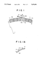
FIG. 1 is a plan view of a deflecting portion of a vacuum pipe for use in a synchrotron orbit radiation device, showing an e of the present invention;
FIG. 1A is a cross-sectional view of part of a wall of a vacuum pipe body of FIG. 1;
FIG. 2 is a plan view of a deflecting portion of a vacuum pipe for use in a synchrotron orbit radiation device, showing another embodiment of the present invention; and
FIG. 3 is a cross-sectional view of a vacuum pipe for use in a conventional synchrotron orbit radiation device.
DETAILED DESCRIPTION OF THE PREFERRED EMBODIMENTS
An embodiment of the present invention will be described below with reference to FIGS. 1 and lA. In FIGS. 1 and 1A, the same reference numerals are used to denote parts or components which are the same as those shown in FIG. 3. The cross-section form of the vacuum pipe body and port portion cell, taken in a direction perpendicular to the orbit of an electron beam may be elliptical, circular or rectangular.
In FIG. 1, a vacuum pipe body 11 provided along the path 2 so that it surrounds an electron beam is made of a thin non-magnetic material (e.g., stainless steel), and has a smooth inner wall surface 110. The smooth surface refers to a surface having no irregularities, unlike the conventional bellows. A large number of outwardly extending ribs 11a are provided on an outer wall surface 111 of the vacuum pipe body 11 at predetermined intervals in the longitudinal direction of the body 11 (in the direction along the path 2) to reinforce the vacuum pipe body 11. Each of the ribs lla extends along a plane perpendicular to the path 2 over the entire circumference of the outer wall surface 111. Ribs lla for a port portion cell 12, which will be described later, are provided similarly.
A port portion cell 12 interposed in the vacuum pipe body 11 such that it forms part of the path 2 is made of the same material as the vacuum pipe body 11, and has a smooth inner wall surface, like the vacuum pipe body 11. The port portion cell 12 has a port wall 6 transverse to and extending from the vacuum pipe body at one end of the port portion cell 12. The tubular port 5 is mounted on and extends from the wall 6 tangential to the path 2. Ribs 11a are disposed on the outer wall surface of the port portion cell 12. A wall 12a of the port portion cell 12 located on the outer diameter side of the path 2 is inclined relative to a wall 12b thereof located on the inner diameter side of the path 12 tangential to the path 2. That is, in this embodiment, the outer diameter wall 12a is substantially parallel to a center line 5a of the port 5.
In the thus-arranged vacuum pipe for use in the synchrotron orbit radiation device, since the inner wall surface of the vacuum pipe body 11 and port portion cell 12 is smooth, the generation of wakes caused by passage of the electron beam is reduced. Furthermore, since the outer diameter wall 12a of the port portion cell 12 is inclined in the same direction as the port 5, a rapid change in the cross-sectional diameter between the vacuum pipe, body 11 and the port portion cell 12 does not occur, also reducing the generation of wakes.
Consequently, the stability of the path 2 and performance of the acceleration and storage rings are improved, and reliability of the synchrotron orbit radiation device is thus improved. Furthermore, since the welded bellows are not used, the production cost is reduced.
A reduction in the strength of the vacuum pipe body 11 and port portion cell 12, caused by the smooth wall surface, is compensated for by the provision of the ribs lla.
In this embodiment, the outer diameter wall 12a of the port portion cell 12 is substantially parallel to the center line 5a of the port 5. However, it may be smoothly curved toward the port 5, as shown in FIG. 2.
The present invention can also be applied to a vacuum pipe having a plurality of port portion cells 12 and ports 5.
This embodiment employs, as a charged particle beam, an electron beam. However, a positively charged beam may also be used.
Furthermore, the non-magnetic material of the vacuum pipe is not limited to stainless steel.
As will be understood from the foregoing description, the vacuum pipe for use in the synchrotron orbit radiation device includes a vacuum pipe body having a smooth inner wall surface and reinforcing ribs on the outer wall surface thereof, and a port portion cell whose outer diameter side wall is inclined toward the port 5 relative to the inner diameter side wall thereof. Consequently, a rapid change in the cross-sectional diameter is avoided, and the formation of wakes is reduced, thus improving stability of the orbit of the charged particle beam. As a result, the synchrotron orbit radiation is improved, the production cost is reduced.