US517025A - Screw-propeller - Google Patents
Screw-propeller Download PDFInfo
- Publication number
- US517025A US517025A US517025DA US517025A US 517025 A US517025 A US 517025A US 517025D A US517025D A US 517025DA US 517025 A US517025 A US 517025A
- Authority
- US
- United States
- Prior art keywords
- screw
- blades
- water
- propeller
- blade
- Prior art date
- Legal status (The legal status is an assumption and is not a legal conclusion. Google has not performed a legal analysis and makes no representation as to the accuracy of the status listed.)
- Expired - Lifetime
Links
- XLYOFNOQVPJJNP-UHFFFAOYSA-N water Substances O XLYOFNOQVPJJNP-UHFFFAOYSA-N 0.000 description 21
- 238000010276 construction Methods 0.000 description 1
- UFULAYFCSOUIOV-UHFFFAOYSA-N cysteamine Chemical compound NCCS UFULAYFCSOUIOV-UHFFFAOYSA-N 0.000 description 1
- 239000007788 liquid Substances 0.000 description 1
- 239000007787 solid Substances 0.000 description 1
Images
Classifications
-
- B—PERFORMING OPERATIONS; TRANSPORTING
- B63—SHIPS OR OTHER WATERBORNE VESSELS; RELATED EQUIPMENT
- B63H—MARINE PROPULSION OR STEERING
- B63H1/00—Propulsive elements directly acting on water
- B63H1/02—Propulsive elements directly acting on water of rotary type
- B63H1/12—Propulsive elements directly acting on water of rotary type with rotation axis substantially in propulsive direction
-
- B—PERFORMING OPERATIONS; TRANSPORTING
- B64—AIRCRAFT; AVIATION; COSMONAUTICS
- B64C—AEROPLANES; HELICOPTERS
- B64C11/00—Propellers, e.g. of ducted type; Features common to propellers and rotors for rotorcraft
- B64C11/46—Arrangements of, or constructional features peculiar to, multiple propellers
- B64C11/48—Units of two or more coaxial propellers
Definitions
- the invention relates to the class of screw propellers that are adapted to be attached to the exterior of a boat, and the Object is to provde a simple propeller so formed that when in motion the blades will act upon the water in such manner as to utilize the utmost resistance that can be afforded by the water to the blades, and thus obtain the greatest effect of the screw.
- the invention resides in a propeller having blades set upon substantially the same pitch of the screw, but projecting outwardly at varying angles, so as to thrust against the Water in different lines, as more particularly hereinafterdescribed and pointed out in the claims.
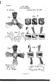
- FIG. 1 is a plan of a propeller embodying the improvements.
- Fig. 2 represents a top edge view of each of the blades of this propeller, and also Vertical Sections of the same, in order to .illustrate the angle at which the blades project from the hub.
- Fig. 3 is a diagramnatic view illustrating the manner in which these blades thrust against the water when in motion.
- Fig. 4 is a plan of a propeller with four blades, embodying the invention; and Fig. 5 are Sections of the blades of this latter propeller to show the angles at which they project from their hub.
- the propeller shown in Fig. 1 has three blades, a, b, and c, which blades are set upon the hub on the pitch of the desired screw. These blades, which may be made flat, as shown, or may be curved on the true pitch of the screw, are made to project from the hub at difierent angles, that is, the blade a, as is shown in plan and section in Fig. 2, projects outwardly straight or at right angles to the axis of the screw; while the blade b is shown as inclining forwardly With relation to the axis of the screw; and the blade c inclines from the hub rearwardly.
- the blade b which is set upon the same or substantially the same pitch but is inclined forwardly, in its spiral movement forward thrusts outwardly as *well as rearwardly and tends to throw the Water which it acts upon outward somewhat centrifugally or in an increasing helix with relation to the axis of the screw; and the blade c, having the same pitch but inclined rear- Wardly, in its spiral movement forward tends to thrust the water inward toward the axis of the screw or to compact the water at the center.
- the blade a that projects straight outward from the hub, thrusts against water which is backed by water directly behind it; while the blade b thrusts against water which is backed by water outside of the center of disturbance created by the -rotation of the screw, and the blade c thrusts against water that is thrown in toward the center or compacted along the axis; and by combiningthese features a propeller is produced in which the thrust of the blades is against water that is backed by solid water, or Water that has not already been given a motion in the-direction of the thrust, by the passage of the preceding blade of the screw; and thus more resistance 'of water for thethrusts of the blades is 'obtained, and the entire effective'ness of the screw-is secured.
- the propeller shown in Fig. 4 has four blades, the two blades marked d being set diametrically opposite on the pitch of the screw and eXtending outwardly straight or at right angles to the axis of the screw, as shown in Fig. 5, so as to thrust directly backward, or spirally to the. axis of the screw; while the other two blades e, which are set upon the same pitch', are inclined forwardly as shown in Fig. 5, so as to thrust outwardly as well as rearwardly as they advance, that is, these' blades tend to throw the water in a spiral helix.
- the blades do not have to act against water which is backed by water that is already churned up and given a motion, or set into a current in the same direction as the thrust, by the pre- IOO vious blade, so that the liquid medium in which the screw Works is as dense as possible.
- a propeller consisting of a hub, and a plural number of blades set upon the hub on the pitch of a screW and projeeting therefrom at difierent angles With relation to the axis of specified.
Landscapes
- Engineering & Computer Science (AREA)
- Aviation & Aerospace Engineering (AREA)
- Chemical & Material Sciences (AREA)
- Combustion & Propulsion (AREA)
- Mechanical Engineering (AREA)
- Ocean & Marine Engineering (AREA)
- Mixers Of The Rotary Stirring Type (AREA)
Description
A. w. CASH; SGREW PEOPELLER.
NNNNNNNNNNNNNNNNNNNNNNNNNNNNNN v.
Patented Mar. 27,1894. 4
. UNITED v STATES PATENT OFFICE.
ALFRED WELLS CASE, OF HIGHLAND PARK, CONNECTICUT.
SCREvW-PROPELLER.
SPEGIFICATION forming part of Letters Patent No. 517,025, dated March 27, 1894.
Application fi ed July 5, 18 93. Serial Na. 479,557- (No model.)
T all whom it may concern:
Be it known that I, ALFRED WELLS CAsE, a citizen of the United States, residing at Highland Park, in the county of H artford and State of Connecticut, have invented certain new and useful Improvements in Propellers, of which the following is a specification.
The invention relates to the class of screw propellers that are adapted to be attached to the exterior of a boat, and the Object is to provde a simple propeller so formed that when in motion the blades will act upon the water in such manner as to utilize the utmost resistance that can be afforded by the water to the blades, and thus obtain the greatest effect of the screw.
To this end the invention resides in a propeller having blades set upon substantially the same pitch of the screw, but projecting outwardly at varying angles, so as to thrust against the Water in different lines, as more particularly hereinafterdescribed and pointed out in the claims.
Referring to the accompanying drawings:-- Figure 1 is a plan of a propeller embodying the improvements. Fig. 2 represents a top edge view of each of the blades of this propeller, and also Vertical Sections of the same, in order to .illustrate the angle at which the blades project from the hub. Fig. 3 is a diagramnatic view illustrating the manner in which these blades thrust against the water when in motion. Fig. 4: is a plan of a propeller with four blades, embodying the invention; and Fig. 5 are Sections of the blades of this latter propeller to show the angles at which they project from their hub.
The propeller shown in Fig. 1 has three blades, a, b, and c, which blades are set upon the hub on the pitch of the desired screw. These blades, which may be made flat, as shown, or may be curved on the true pitch of the screw, are made to project from the hub at difierent angles, that is, the blade a, as is shown in plan and section in Fig. 2, projects outwardly straight or at right angles to the axis of the screw; while the blade b is shown as inclining forwardly With relation to the axis of the screw; and the blade c inclines from the hub rearwardly. When the propeller is forned in' this way the action of the thrusts of the blades on the water may beillustrated as in Fig. 3; the blade a, which projects outwardly on the pitch of the screw at right angles from the hub of the'propeller, thrusts backward and sets the water which it enters moving backward parallel with or spirally with the. axis of *the screw; the blade b, which is set upon the same or substantially the same pitch but is inclined forwardly, in its spiral movement forward thrusts outwardly as *well as rearwardly and tends to throw the Water which it acts upon outward somewhat centrifugally or in an increasing helix with relation to the axis of the screw; and the blade c, having the same pitch but inclined rear- Wardly, in its spiral movement forward tends to thrust the water inward toward the axis of the screw or to compact the water at the center.
.In aconstruction like this the blade a, that projects straight outward from the hub, thrusts against water which is backed by water directly behind it; while the blade b thrusts against water which is backed by water outside of the center of disturbance created by the -rotation of the screw, and the blade c thrusts against water that is thrown in toward the center or compacted along the axis; and by combiningthese features a propeller is produced in which the thrust of the blades is against water that is backed by solid water, or Water that has not already been given a motion in the-direction of the thrust, by the passage of the preceding blade of the screw; and thus more resistance 'of water for thethrusts of the blades is 'obtained, and the entire effective'ness of the screw-is secured.
The propeller shown in Fig. 4 has four blades, the two blades marked d being set diametrically opposite on the pitch of the screw and eXtending outwardly straight or at right angles to the axis of the screw, as shown in Fig. 5, so as to thrust directly backward, or spirally to the. axis of the screw; while the other two blades e, which are set upon the same pitch', are inclined forwardly as shown in Fig. 5, so as to thrust outwardly as well as rearwardly as they advance, that is, these' blades tend to throw the water in a spiral helix. By means of this construction, the blades do not have to act against water which is backed by water that is already churned up and given a motion, or set into a current in the same direction as the thrust, by the pre- IOO vious blade, so that the liquid medium in which the screw Works is as dense as possible.
I do not limit myself to the precise number of blades that may be used, nor the number that may project at the same angle of inclination; neither do I limit myself to the exact outline, pitchor angle of inclination shown, as these may be varied for diiferent purposes without departing from the invention.
I claim as my invention- 1. A propeller consisting of a hub, and a plural number of blades set upon the hub on the pitch of a screW and projeeting therefrom at difierent angles With relation to the axis of specified.
ALFRED WELLS CASE.
Witnesses:
H. R. WILLIAMS, 0.' E. BUCKLAND.
Publications (1)
| Publication Number | Publication Date |
|---|---|
| US517025A true US517025A (en) | 1894-03-27 |
Family
ID=2585830
Family Applications (1)
| Application Number | Title | Priority Date | Filing Date |
|---|---|---|---|
| US517025D Expired - Lifetime US517025A (en) | Screw-propeller |
Country Status (1)
| Country | Link |
|---|---|
| US (1) | US517025A (en) |
-
0
- US US517025D patent/US517025A/en not_active Expired - Lifetime
Similar Documents
| Publication | Publication Date | Title |
|---|---|---|
| US506572A (en) | Propeller | |
| US855131A (en) | Screw-propeller. | |
| US285212A (en) | Screw-propeller | |
| US517025A (en) | Screw-propeller | |
| US1363660A (en) | Propeller | |
| US732568A (en) | Self-clearing propeller. | |
| US885174A (en) | Propeller-wheel. | |
| US505402A (en) | Screw-propeller | |
| US496857A (en) | Propeller | |
| US350278A (en) | Screw-propeller | |
| US345761A (en) | Screw-propeller | |
| US666077A (en) | Screw-propeller and rudder. | |
| US435602A (en) | Azadore m | |
| US890973A (en) | Ship's propeller. | |
| US559890A (en) | Screw-propeller | |
| US997587A (en) | Propeller. | |
| US170937A (en) | Improvement in screw-propellers | |
| US624761A (en) | Screw-propeller | |
| US1180587A (en) | Adjustable thrust-counteracting mechanism for centrifugal pumps. | |
| US779473A (en) | Propeller. | |
| US754710A (en) | Propelling apparatus for vessels. | |
| US417888A (en) | Centrifugal auxiliary propeller | |
| US152973A (en) | Improvement in screw-propellers | |
| US1078159A (en) | Propeller. | |
| US283336A (en) | Eobeet m |