US5168719A - Food preparation table with open air food storage - Google Patents
Food preparation table with open air food storage Download PDFInfo
- Publication number
- US5168719A US5168719A US07/813,384 US81338491A US5168719A US 5168719 A US5168719 A US 5168719A US 81338491 A US81338491 A US 81338491A US 5168719 A US5168719 A US 5168719A
- Authority
- US
- United States
- Prior art keywords
- condiment
- plenum
- disposed
- wall
- cabinet
- Prior art date
- Legal status (The legal status is an assumption and is not a legal conclusion. Google has not performed a legal analysis and makes no representation as to the accuracy of the status listed.)
- Expired - Lifetime
Links
- 235000013305 food Nutrition 0.000 title claims abstract description 239
- 238000002360 preparation method Methods 0.000 title claims abstract description 123
- 235000013409 condiments Nutrition 0.000 claims abstract description 372
- 238000005057 refrigeration Methods 0.000 claims abstract description 40
- 238000001816 cooling Methods 0.000 claims abstract description 39
- 239000002826 coolant Substances 0.000 claims description 2
- 238000001704 evaporation Methods 0.000 claims 1
- 230000008020 evaporation Effects 0.000 claims 1
- 239000003570 air Substances 0.000 description 218
- 238000000926 separation method Methods 0.000 description 6
- 239000004615 ingredient Substances 0.000 description 5
- 238000009413 insulation Methods 0.000 description 4
- 230000002093 peripheral effect Effects 0.000 description 4
- 235000013550 pizza Nutrition 0.000 description 3
- 238000004064 recycling Methods 0.000 description 3
- 238000012986 modification Methods 0.000 description 2
- 230000004048 modification Effects 0.000 description 2
- 229910001220 stainless steel Inorganic materials 0.000 description 2
- 239000010935 stainless steel Substances 0.000 description 2
- 239000012080 ambient air Substances 0.000 description 1
- 238000001514 detection method Methods 0.000 description 1
- 229940014425 exodus Drugs 0.000 description 1
- 230000005484 gravity Effects 0.000 description 1
- 239000002184 metal Substances 0.000 description 1
- 239000003507 refrigerant Substances 0.000 description 1
- 230000000630 rising effect Effects 0.000 description 1
- 239000002023 wood Substances 0.000 description 1
Images


Classifications
-
- F—MECHANICAL ENGINEERING; LIGHTING; HEATING; WEAPONS; BLASTING
- F25—REFRIGERATION OR COOLING; COMBINED HEATING AND REFRIGERATION SYSTEMS; HEAT PUMP SYSTEMS; MANUFACTURE OR STORAGE OF ICE; LIQUEFACTION SOLIDIFICATION OF GASES
- F25D—REFRIGERATORS; COLD ROOMS; ICE-BOXES; COOLING OR FREEZING APPARATUS NOT OTHERWISE PROVIDED FOR
- F25D17/00—Arrangements for circulating cooling fluids; Arrangements for circulating gas, e.g. air, within refrigerated spaces
- F25D17/04—Arrangements for circulating cooling fluids; Arrangements for circulating gas, e.g. air, within refrigerated spaces for circulating air, e.g. by convection
- F25D17/06—Arrangements for circulating cooling fluids; Arrangements for circulating gas, e.g. air, within refrigerated spaces for circulating air, e.g. by convection by forced circulation
- F25D17/062—Arrangements for circulating cooling fluids; Arrangements for circulating gas, e.g. air, within refrigerated spaces for circulating air, e.g. by convection by forced circulation in household refrigerators
- F25D17/065—Arrangements for circulating cooling fluids; Arrangements for circulating gas, e.g. air, within refrigerated spaces for circulating air, e.g. by convection by forced circulation in household refrigerators with compartments at different temperatures
-
- A—HUMAN NECESSITIES
- A47—FURNITURE; DOMESTIC ARTICLES OR APPLIANCES; COFFEE MILLS; SPICE MILLS; SUCTION CLEANERS IN GENERAL
- A47F—SPECIAL FURNITURE, FITTINGS, OR ACCESSORIES FOR SHOPS, STOREHOUSES, BARS, RESTAURANTS OR THE LIKE; PAYING COUNTERS
- A47F3/00—Show cases or show cabinets
- A47F3/04—Show cases or show cabinets air-conditioned, refrigerated
- A47F3/0404—Cases or cabinets of the closed type
- A47F3/0408—Cases or cabinets of the closed type with forced air circulation
-
- F—MECHANICAL ENGINEERING; LIGHTING; HEATING; WEAPONS; BLASTING
- F25—REFRIGERATION OR COOLING; COMBINED HEATING AND REFRIGERATION SYSTEMS; HEAT PUMP SYSTEMS; MANUFACTURE OR STORAGE OF ICE; LIQUEFACTION SOLIDIFICATION OF GASES
- F25D—REFRIGERATORS; COLD ROOMS; ICE-BOXES; COOLING OR FREEZING APPARATUS NOT OTHERWISE PROVIDED FOR
- F25D2317/00—Details or arrangements for circulating cooling fluids; Details or arrangements for circulating gas, e.g. air, within refrigerated spaces, not provided for in other groups of this subclass
- F25D2317/06—Details or arrangements for circulating cooling fluids; Details or arrangements for circulating gas, e.g. air, within refrigerated spaces, not provided for in other groups of this subclass with forced air circulation
- F25D2317/066—Details or arrangements for circulating cooling fluids; Details or arrangements for circulating gas, e.g. air, within refrigerated spaces, not provided for in other groups of this subclass with forced air circulation characterised by the air supply
- F25D2317/0665—Details or arrangements for circulating cooling fluids; Details or arrangements for circulating gas, e.g. air, within refrigerated spaces, not provided for in other groups of this subclass with forced air circulation characterised by the air supply from the top
-
- F—MECHANICAL ENGINEERING; LIGHTING; HEATING; WEAPONS; BLASTING
- F25—REFRIGERATION OR COOLING; COMBINED HEATING AND REFRIGERATION SYSTEMS; HEAT PUMP SYSTEMS; MANUFACTURE OR STORAGE OF ICE; LIQUEFACTION SOLIDIFICATION OF GASES
- F25D—REFRIGERATORS; COLD ROOMS; ICE-BOXES; COOLING OR FREEZING APPARATUS NOT OTHERWISE PROVIDED FOR
- F25D2400/00—General features of, or devices for refrigerators, cold rooms, ice-boxes, or for cooling or freezing apparatus not covered by any other subclass
- F25D2400/08—Refrigerator tables
Definitions
- the present invention relates to food preparation tables and more particularly to such tables including at least one refrigerated storage compartment beneath the food preparation surface and condiment pans disposed adjacent the food preparation surface.
- the ingredient foodstuff items in the condiment pans may be present in the pans for many hours before being used by the food service worker who is preparing the desired prepared foodstuff, such as pizza or sandwiches, it becomes desirable to keep the ingredient foodstuffs refrigerated at temperatures between 32° and 40° F. Since the ingredient foodstuffs in the condiment pans must be readily available to the food preparer, the condiment pans are not sufficiently accessible if they are enclosed in a refrigerated compartment having a door which must be opened to gain access to the ingredient foodstuffs and closed to keep the ingredient foodstuffs sufficiently cold.
- a number of devices use forced cool air circulation beneath the space occupied by the condiment pans. Examples of such devices are described in U.S. Pat. No. 4,802,340 to Johnson; U.S. Pat. No. 4,457,140 to Rastelli; and U.S. Pat. No. 2,886,395 to Cahn. However, recently the National Sanitation Foundation has promulgated a very strict performance standard for certification of food preparation tables. In an attempt to meet these new standards, one device shown in U.S. Pat. No. 4,685,311 to Rastelli forces cool air from the evaporator to a position well above the open tops of the pans and releases the cooled air to drop down vertically onto the upper surface of the food stored in the pans.
- the food preparation table of the present invention includes a cabinet that defines a food preparation surface extending generally along the length of the cabinet and disposed generally horizontally.
- the cabinet also defines at least one heat-insulated food storage compartment disposed generally beneath the food preparation surface and defining a door for gaining access inside of the food storage compartment.
- the food preparation table of the present invention further desirably includes heat-absorbing refrigeration equipment disposed inside the cabinet and including at least one evaporator and an evaporator fan disposed so that air moves through the evaporator upon operation of the fan. Instead of operating continuously, greater efficiency is achieved in some embodiments by having the evaporator fan operate only when the temperature controller activates the cooling cycle of the refrigeration equipment.
- the cabinet also defines a condiment plenum disposed adjacent to one elongated side edge of the food preparation surface.
- the condiment plenum desirably includes at least one condiment plenum wall that defines a complex structure including at least one air channel and at least one upper louver.
- each complex structure of the condiment plenum wall includes at least one lower louver in one preferred embodiment.
- separate air channels may be provided for the upper louver and the lower louver.
- a second condiment plenum wall is spaced apart from the first condiment plenum wall and is similarly configured as the first condiment plenum wall in terms of the complex structure including the air channel and the louver or louvers.
- the apparatus of the present invention further includes at least one and desirably a plurality of open top condiment pans that are received by the condiment plenum.
- Each upper louver is configured and disposed to face toward the condiment plenum and the condiment pans received therein.
- Each upper louver desirably is disposed above the open top of the condiment pan.
- Each lower louver if any, is disposed to provide air flow beneath and outside the open top of the condiment pan.
- the food preparation table of the present invention desirably includes a cabinet that defines a cool air supply system.
- the cool air supply system desirably includes the upper louvers, an air channel communicating with the upper louvers, and a cooling plenum configured and disposed to receive air passing through the evaporator upon operation of the at least one evaporator fan.
- the food preparation table of the present invention further desirably includes an elongated cool air supply duct, and at least one supply opening that is configured and disposed to connect the elongated cool air supply duct with the food storage compartment.
- the cooling plenum, the elongated cool air supply duct, the upper louvers, the air channel, and the at least one supply opening are configured and disposed to supply from the evaporator, cool air across the tops of the condiment pans and cool air into the food storage compartment.
- An elongated air flow baffle can be disposed along the length of the elongated cool air supply duct or the air supply channel to facilitate cool air distribution along the length of same.
- a second elongated air flow baffle is disposed along the length of the elongated cool air supply duct and parallel to to the first baffle.
- a plurality of air flow dams are disposed transversely to the length of the elongated cool air supply duct and between the two baffles to further assist in ensuring an even distribution of cool air flow into all sections of the condiment plenum to avoid unacceptacle temperature gradients in the condiment pans.
- one or more elongated air flow guides is disposed generally at a small angle from being parallel to the length of the elongated cool air supply duct.
- Each air flow guide is disposed to extend from a site where an air flow dam joins with the first baffle and deviates from a direction parallel to the baffle by only a small angle of about less than five degrees.
- the condiment plenum wall which receives cool air via the elongated cool air duct can be provided with vertically disposed air flow dams that are spaced apart down the length of the cabinet and terminate before reaching the height of the upper louver.
- Each vertical dam is disposed at the site of a transverse air flow dam and assists in ensuring an even distribution of cool air flow into all sections of the condiment plenum.
- the food preparation table of the present invention further includes a return air system.
- the return air system desirably includes a return chamber, a return wall, and at least one return opening.
- the return wall desirably is disposed between the food storage compartment and the return chamber.
- the return wall defines at least one return opening that permits access between the food storage compartment and the return chamber.
- the return chamber and the at least one return opening are desirably configured and disposed to return to the evaporator upon operation of the evaporator fan, relatively warmed air from the food storage compartment.
- the return air system also returns relatively warmed air from the condiment plenum to the evaporator upon operation of the evaporator fan.
- FIG. 1 schematically illustrates an elevated perspective view of a preferred embodiment of the present invention with portions shown in phantom;
- FIG. 2 schematically illustrates a cross-sectional view of a portion of a first preferred embodiment of the air flow passages for the embodiment of the food preparation table of FIG. 1 taken from a perspective looking in the direction indicated by arrows 2--2 and indicating the direction of air flow by the short arrows;
- FIG. 2A schematically illustrates a cross-sectional view of a portion of an alternative embodiment of the air flow passages for the embodiment of the food preparation table of FIG. 1 taken from a perspective looking in the direction indicated by arrows 2--2 and indicating the direction of air flow by the short arrows;
- FIG. 3 schematically illustrates a front plan view of a cut-away of a preferred embodiment of the present invention such as shown in FIGS. 1 and 2;
- FIG. 4 schematically illustrates an elevated perspective view of a second preferred embodiment of the present invention with portions cut away and portions shown in phantom (dashed lines);
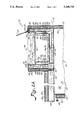
- FIG. 5 schematically illustrates a cut-away side plan view of the preferred embodiment of the present invention such as shown in FIG. 4;
- FIG. 5A schematically illustrates a side plan view of an alternative embodiment of a portion of a preferred embodiment of the present invention such as shown in FIGS. 4, 5 and 7;
- FIG. 5B schematically illustrates a front plan view of the alternative embodiment shown in FIG. 5A taken from a perspective looking in the direction indicated by arrows 5B--5B in FIG. 5A and with the short arrows indicating the direction of air flow;
- FIG. 6 schematically illustrates an elevated perspective view of a cut-away of the preferred embodiment of the present invention such as shown in FIGS. 1 and 2 with portions cut away and with the short arrows indicating the direction of air flow;
- FIG. 7 schematically illustrates a top plan view of a portion of the second preferred embodiment of the food preparation table of FIGS. 4 and 5 taken from a perspective looking in the direction indicated by arrows 7--7 in FIG. 5 and with the short arrows indicating the direction of air flow;
- FIG. 8 schematically illustrates an elevated perspective view of selected components of the preferred embodiment of the present invention such as shown in FIGS. 1, 2, 3 and 6 with other components removed and with the short arrows indicating the direction of air flow.
- FIGS. 1, 2, 3 and 6 A preferred embodiment of the food preparation table of the present invention is shown in FIGS. 1, 2, 3 and 6, and is represented generally by the numeral 20.
- Table 20 is especially useful for preparing pizza.
- FIGS. 4, 5 and 7 An alternative preferred embodiment of the food preparation table of the present invention is shown in FIGS. 4, 5 and 7 and is represented generally by the numeral 22.
- Table 22 is especially useful for preparing sandwiches.
- Another alternative embodiment which is generally designated by the numeral 20 and shown in FIGS. 1, 2A and 3, is also especially useful for preparing pizza.
- a cabinet In accordance with the present invention, a cabinet is provided.
- the cabinet defines a food preparation surface, which is an exterior top surface of the cabinet or a separate cutting surface carried by the exterior top surface of the cabinet and extends generally along the length of the cabinet.
- the food preparation surface is disposed generally horizontally at a height that is convenient for the person who prepares the food on the food preparation surface.
- a cabinet is generally designated by the numeral 24.
- cabinet 24 is carried above the floor by a plurality of legs 23 (FIGS. 1 and 3) or casters 21 (FIGS. 4 and 5).
- a food preparation surface in the form of a countertop 26 desirably forms an exterior top surface of cabinet 24.
- Countertop 26 extends generally along the length of cabinet 24 and is disposed generally horizontally at a height convenient for persons who prepare food on countertop 26.
- cabinet 24 desirably is formed of stainless steel and countertop 26 desirably is formed of a surface such as wood or plastic that functions as a cutting board and easily can be kept clean enough for food preparation.
- cabinet 24 and countertop 26 are both desirably formed of stainless steel.
- insulation 25 (represented by sinsudoidal wavy lines) is disposed beneath countertop 26.
- the cabinet defines at least one heat insulated, food storage compartment disposed beneath the food preparation surface.
- the cabinet includes at least one door which permits access to the inside of the food storage compartment.
- a heat insulated food storage compartment 27 desirably is defined by an endwall 28, a bottom wall 30, a ceiling wall 32, a rear wall 34, and a separation wall 36 (FIG. 3).
- heat insulation 25 generally is disposed between the walls defining food storage compartment 27 and the walls defining cabinet 24.
- a food storage compartment 37 is defined by a pair of end walls 38, a top wall 40 (FIG. 5) disposed beneath countertop 26, a bottom wall 42, and a separation wall 44.
- heat insulation 25 desirably is provided between the walls defining food storage compartment 37 and the exterior walls of cabinet 24.
- cabinet 24 defines at least one door 46 for gaining access inside food storage compartment 27 or 37.
- each door 46 has a handle 48 and hinges 50 by which each door 46 can be opened for gaining access inside food storage compartment 27 or 37.
- each door 46 is provided with heat insulation 25.
- the cabinet defines a heat insulated housing for the heat-generating refrigeration equipment.
- a housing is indicated generally by the numeral 52 and is disposed within cabinet 24. Separation wall 36 (FIG. 3) or 44 (FIGS. 4 and 5) is heat insulated from housing 52 and separates housing 52 from food storage compartment 27 (FIG. 3) or 37 (FIGS. 4 and 5).
- housing 52 defines a top wall 51, which is heat insulated from food storage compartment 27 and from a cooling plenum 120 (described hereafter).
- housing 52 defines a top wall 51, which is heat insulated from food storage compartment 37.
- housing 52 is disposed between separation wall 44 and the rear exterior wall 54 (FIG. 5) of cabinet 24.
- the heat-generating refrigeration equipment disposed inside housing 52 includes a condenser 57, a compressor 49 (not shown in FIG. 4 and largely obscured in FIG. 5) which compresses the coolant supplied to an evaporator (described below), and a condenser fan 59 (shown in phantom in FIGS. 3 and 5 by the dashed lines).
- housing 52 can be further defined by a removable access panel 53, which permits access to the interior of housing 52 for servicing the heat-generating refrigeration equipment from the front of cabinet 24.
- Panel 53 desirably includes a plurality of air circulation louvers 55 which permit ambient air to enter housing 52 and heated air to escape from housing 52 and enter the surrounding environment.
- the heat-absorbing refrigeration equipment is disposed in communication with a cooling plenum, which receives cooled air for distribution to the food storage compartment and elsewhere as described hereafter.
- the heat-absorbing refrigeration equipment disposed in communication with the cooling plenum includes at least one fan and an evaporator, which are disposed so that air moved by operation of the fan also moves through the evaporator and becomes cooled before entering the cooling plenum.
- the space defined by the cooling plenum is indicated generally in FIGS. 3, 5 and 6 by the numeral 120. As embodied herein and schematically shown in FIGS.
- an evaporator 58 has a discharge face 118 which is disposed to define one boundary of cooling plenum 120, and at least one fan 56 is disposed to move air through evaporator 58 upon operation of fan 56.
- Two fans 56 are shown at least partially in FIG. 6, but only one is visible in the views schematically shown in FIGS. 3 and 5. As schematically shown by arrows designated 60 in FIGS. 3, 5 and 6 for example, fan 56 moves air through evaporator 58 and into cooling plenum 120.
- Evaporator 58 desirably is a finned tube evaporator that carries refrigerant circulating through a plurality of tubes 62 extending transversley through a plurality of fins 64 disposed side-by-side. Only the end-most fin 64 is visible in the view depicted in FIG. 3.
- a condensate pan 63 is disposed beneath evaporator 58.
- an electric coil defrost heater 75 desirably is disposed between evaporator 58 and condensate pan 63 to remove frost from the evaporator.
- a defrost heater 75 is also schematically shown in FIG.
- FIG. 5 but desirably is omitted from the FIG. 5 embodiment.
- a drain tube 73 connects pan 63 to housing 52 to allow condensate to drain from pan 63 into housing 52.
- the evaporator fan is operated intermittently under the control of a temperature controller that also controls operation of the refrigeration equipment in the cooling mode.
- a temperature controller 33 is mounted behind a wall 142 which defines the food storage compartment 27 or 37. Controller 33 is electrically connected to control operation of evaporator fan 56 as well as compressor 49 and contains a thermostat which senses temperature. The temperature to be sensed can be preselected via a control knob 35 which extends into the respective food storage compartment 27 or 37 and forms a part of temperature controller 33.
- temperature controller 33 Upon detection of a temperature higher than has been set by control knob 35, temperature controller 33 operates the refrigeration equipment (compressor 49) in the cooling mode.
- temperature controller 33 desirably is configured and connected electrically to cause evaporator fan 56 to operate only during such time as the refrigeration equipment is being operated in the cooling mode. This intermittent operating control sequence for the evaporator fan limits operation of the fan to such times as the compressor is operating in the cooling mode of the refrigeration equipment and yields a more efficient operation of the refrigeration equipment in such embodiments.
- evaporator fan 56 desirably is configured and connected electrically to operate continuously, even during such time as the refrigeration equipment is not being operated by temperature controller in the cooling mode.
- the cabinet defines a condiment plenum that is disposed adjacent to one of the elongated side edges of the food preparation surface.
- the condiment plenum is further defined by a front wall that is disposed adjacent to the one side edge of the food preparation surface.
- the condiment plenum is formed as part of the refrigerated food storage compartment but is still disposed adjacent to the one side edge of the food preparation surface.
- the condiment plenum further is defined by a rear wall that either is spaced away from and opposite to the front wall (FIGS. 1-3 and 6) or to the rear of the refrigerated food storage compartment (FIGS.
- the plenum defines a bottom wall that extends from the rear wall.
- the condiment plenum is configured to receive a plurality of open top condiment pans, which hold foodstuffs used by the food preparer to assemble food servings on the food preparation surface.
- a condiment plenum is indicated generally by the numeral 66.
- condiment plenum 66 is disposed adjacent an elongated side edge 68 of the food preparation surface.
- plenum 66 can include a front condiment plenum wall 70 disposed adjacent side edge 68 of countertop 26.
- a rear condiment plenum wall 72 can be spaced apart from front condiment plenum wall 70.
- condiment plenum 66 further defines a bottom condiment plenum wall 74 which extends from rear plenum wall 72 and between front plenum wall 70 and rear plenum wall 72 to connect same.
- condiment plenum 66 is defined in part by a rear plenum wall 72 from which a bottom plenum wall 74 extends toward refrigerated food storage compartment 37.
- plenum 66 can be provided with one or more covers 67 which are pivotally mounted to selectively limit access to plenum 66.
- each cover 67 can be pivotally mounted to the top of rear plenum wall 72 via hinges 69 (FIGS. 2, 2A).
- each cover 67 can be pivotally mounted to the top of the cabinet 24 wherein cover 67 is in the form of a triangular hood that is pivotally mounted at 65 so that the weight of cover 67 is balanced to maintain cover 67 in a stable position at each opposite extreme position of pivotal movement.
- cover 67 is in the form of a triangular hood that is pivotally mounted at 65 so that the weight of cover 67 is balanced to maintain cover 67 in a stable position at each opposite extreme position of pivotal movement.
- One extreme position (dashed line in FIG.
- each cover 67 can be provided with a handle 71 for manually lifting or lowering cover 67.
- plenum 66 desirably is configured with a front ledge 76 disposed along the length of front plenum wall 70 and a rear ledge 78 disposed along the length of rear plenum wall 72.
- a removable frame 79 is formed in a rectangular shape and configured to rest at least partly on a pan support member 77.
- a peripheral ledge 83 is disposed along the length of rear plenum wall 72, and frame 79 is configured to rest at least partly on peripheral ledge 83.
- peripheral ledge 83 extends on each side from rear condiment plenum wall 72 and toward pan support members 77. Ledges 76, 78 and 83 are thus configured to receive a plurality of open top condiment pans 80.
- each condiment pan 80 defines a peripheral lip 82 at the top surface thereof. Lip 82 desirably extends completely around pan 80 and rests atop ledges 76, 78 or frame 79 when pan 80 is received inside plenum 66. Each pan 80 is desirably symmetrically configured so that it can be rotated 90° and still fit inside plenum 66. However, elongated condiment pans having two relatively longer side dimensions also can be provided. As schematically shown in FIGS. 2, 2A, 5 and 6 for example, each pan 80 defines side walls 84 extending from top lip 82. As schematically shown in FIGS.
- each pan 80 further defines a pan bottom wall 86.
- Each condiment pan 80 is configured so that its bottom wall 86 leaves an air space 88 between the pan bottom 86 and condiment plenum bottom wall 74 when pan 80 is disposed in condiment plenum 66.
- the condiment plenum is defined by at least one condiment plenum wall which defines a complex wall structure.
- the condiment plenum is defined by a pair of spaced apart condiment plenum walls, and each condiment plenum wall defines a complex wall structure.
- each complex condiment plenum wall structure is defined by an interior wall panel 43 which faces the interior of and defines at least a portion of the interior of condiment plenum 66.
- FIGS. 2, 2A, 5, and 6 for example, each complex condiment plenum wall structure is defined by an interior wall panel 43 which faces the interior of and defines at least a portion of the interior of condiment plenum 66.
- each complex condiment plenum wall structure is defined by an exterior wall panel 45 which is disposed generally parallel to and spaced apart from and opposite to interior wall panel 43. Exterior wall panel 45 faces away from the interior of condiment plenum 66.
- the complex condiment plenum wall structure includes at least one, and desirably a plurality, of upper louvers defined in the upper regions of interior wall panel 43 of at least one of the front and rear condiment plenum walls. Each upper louver is disposed above the open tops of the condiment pans. The upper louvers of one of the condiment plenum walls are configured and disposed to direct airflow in a downward direction toward the condiment pans.
- both front and rear condiment plenum walls FIGS.
- the upper louvers of the other of the condiment plenum walls are configured and disposed to receive airflow in an upward direction away from the condiment pans.
- the upper louvers of the front plenum wall desirably are disposed to face across from the upper louvers of the rear plenum wall.
- a first or front plenum wall 70 defines a plurality of upper louvers 90 defined in the upper region of front wall 70.
- upper louvers 90 of front condiment plenum wall 70 are desirably configured to extend toward and into front wall 70 at about a 45 degree angle in a manner that extends away from plenum 66 and disposes the upper louver opening 92, which is formed as an elongated slit through front condiment plenum wall 70, so that air entering these louver openings 92 from within front condiment plenum wall 70 and moving toward rear plenum wall 72 and pans 80, is guided to travel in a downwardly direction toward pans 80 at about a 45 degree angle from the surface of front condiment plenum wall 70.
- each upper louver 90 prevents foodstuff which happens to enter openings 92, from getting past upper louvers 90 of front plenum wall 70 and falling inside the complex wall structure of front plenum wall 70, and thus contributes to the sanitary condition of the food preparation table of the present invention.
- the foodstuff would need to travel against the force of gravity far enough in an upward direction to get past the free edge of louver 90.
- front plenum wall 70 defines a plurality of upper louvers 90 defined in the upper region of front wall 70.
- Upper louvers 90 of front plenum wall 70 are desirably configured to extend away from front wall 70 at about a 45 degree angle in a manner that extends toward plenum 66 and hoods or shields the upper louver opening 92, which is formed in front wall 70 beneath where each corresponding upper louver 90 remains attached to front wall 70, so that air exiting these upper louver openings 92 from within front wall 70 and moving toward plenum 66 and pans 80, travels in a downwardly direction toward pans 80 at about a 45 degree angle from the surface of front plenum wall 70.
- the downward directional bias of the front wall's upper louvers 90 prevents foodstuff which falls from above from entering upper louver openings 92 of upper louvers 90, and thus contributes to the sanitary condition of the food preparation table of the present invention.
- rear condiment plenum wall 72 also defines a plurality of upper louvers 94 in the upper region of rear wall 72.
- Upper louvers 94 of rear plenum wall 72 are desirably configured to extend away from rear wall 72 at about a 45 degree angle in a manner that extends away from plenum 66 and disposes the upper louver opening 96, which is formed as an elongated slit in rear wall 72, so that air entering these louver openings 96 from within condiment plenum 66 and moving toward rear plenum wall 72 and away from pans 80, travels in an upwardly direction away from pans 80 at about a 45 degree angle from the surface of rear plenum wall 72.
- each upper louver 94 prevents foodstuff which happens to enter upper louver openings 96, from getting past upper louvers 94 of rear plenum wall 72 and falling inside the complex wall structure of rear plenum wall 72, and thus contributes to the sanitary condition of the food preparation table of the present invention.
- upper louvers 94 of rear wall 72 could be configured and disposed so that the upper louver opening 96 is formed below where each upper louver 94 remains attached to rear condiment plenum wall 72 and louvers 94 would extend downwardly toward plenum 66 in a manner similar to the configuration of upper louvers 90 shown in FIG. 2.
- upper louvers 90, 94 are configured and disposed above the open tops of condiment pans 80.
- Upper louvers 90 of front condiment plenum wall 70 face toward condiment pans 80, while upper louvers 94 of rear condiment plenum wall 72 face away from condiment pans 80.
- upper louvers 90 of front wall 70 face across from upper louvers 94 of rear wall 72, which is important for controlling the direction of cool air flow, as explained hereafter.
- the complex wall structure of each of the front and rear condiment plenum walls includes an air channel extending along the length of each of the respective front and rear walls. Each air channel is configured to communicate with the upper louvers of the respective condiment plenum wall.
- front plenum wall 70 defines a complex structure including an upper supply channel 106 defined between interior wall panel 43 and exterior wall panel 45. Upper supply channel 106 is configured and disposed in communication with upper louver openings 92 in front plenum wall 70.
- rear condiment plenum wall 72 defines a complex structure including an upper return channel 110, which is configured and disposed in communication with upper louver openings 96 of rear plenum wall 72 and is defined between interior wall panel 43 and exterior wall panel 45.
- the complex wall structure of each of the front and rear condiment plenum walls includes a plurality of lower louvers defined in the lower regions of the front and rear walls.
- Lower louvers also could be provided in the embodiment shown in FIG. 2 for example.
- the lower louvers in one of the plenum walls are configured and disposed to direct airflow in a downward direction toward the condiment pans, while the lower louvers in the other of the plenum walls are configured and disposed to direct airflow in an upward direction away from the condiment pans.
- the lower louvers are disposed below the open tops of the condiment pans.
- the lower louvers of the front wall desirably are disposed to face across from the lower louvers of the rear wall.
- front plenum wall 70 defines a plurality of lower louvers 98 defined in the lower region of front plenum wall 70.
- Lower louvers 98 of front plenum wall 70 are desirably configured to extend away from front wall at about a 45 degree angle in a manner that extends away from plenum 66 and disposes the lower louver opening 100 formed in the lower portion of front wall 70 above where each lower louver 98 remains attached to front wall 70, so that air entering these lower louver openings 100 from within front wall 70 and moving toward plenum 66 and pans 80, travels in an downwardly direction away from front plenum wall 70 and toward pans 80 at about a 45 degree angle from the surface of front plenum wall 70.
- each lower louver 98 directs air to air space 88 beneath pans 80 and toward rear plenum wall 72.
- lower louvers 98 of front wall 70 alternatively could be configured and disposed so that the lower louver opening 100 is formed in the lower portion of front wall 70 below where each lower louver 98 remains attached to front wall 70.
- rear plenum wall 72 also defines a plurality of lower louvers 102 in the lower region of rear wall 72.
- Lower louvers 102 of rear plenum wall 72 are desirably configured to extend away from rear wall 72 at about a 45 degree angle in a manner that extends away from plenum 66 and disposes the lower louver opening 104 formed in rear wall 72 above where each lower louver 102 remains attached to rear wall 72.
- air entering these lower louver openings 104 from within plenum 66 and moving toward rear plenum wall 72 and away from pans 80 travels in an upwardly direction away from pans 80 at about a 45 degree angle from the surface of rear plenum wall 72.
- each lower louver 102 corresponds to the direction of relatively warmed air rising within rear plenum wall 72, and thus facilitates the exodus of the relatively warm return air from beneath pans 80 of the food preparation table of the present invention.
- lower louvers 102 of rear wall 72 could be configured and disposed so that the lower louver opening 104 is formed in the lower portion of rear wall 72 below where each lower louver 102 remains attached to rear condiment plenum wall 72.
- lower louvers 98, 102 are configured and disposed below open tops of condiment pans 80 and are disposed in a direction away from pans 80.
- the upward directional bias of each lower louver 98, 102 prevents foodstuff from getting past either front condiment plenum wall 70 or rear condiment plenum wall 72 through respective lower louver openings 100, 104 of lower louvers 98, 102, and thus contributes to the sanitary condition of the food preparation table of the present invention.
- FIG. 2A for example, lower louvers 98, 102 are configured and disposed below open tops of condiment pans 80 and are disposed in a direction away from pans 80.
- the upward directional bias of each lower louver 98, 102 prevents foodstuff from getting past either front condiment plenum wall 70 or rear condiment plenum wall 72 through respective lower louver openings 100, 104 of lower louvers 98, 102, and thus contributes to the sanitary condition of the food preparation table of the present invention.
- lower louver openings 100 of front plenum wall 70 face across from lower louver openings 104 of rear plenum wall 72, which is important for controlling the direction of cool air flow in this embodiment of the invention, as explained hereafter.
- lower louver openings 100, 104 desirably are disposed in communication with the air space 88 disposed between plenum bottom wall 74 and bottoms 86 of condiment pans 80.
- each of the complex wall structures of the front and rear condiment plenum walls defines a pair of air channels extending along the lengths of each of the front and rear walls.
- One of the pair of air channels is configured to communicate with the upper louvers of the wall.
- the other of the pair of air channels is configured to communicate with the lower louvers of the condiment plenum wall.
- each front and rear condiment plenum wall structure can define only a single air channel (as in FIGS. 2 and 6 for example), rather than two channels separated from one another as shown in the FIG. 2A. embodiment.
- One way to accomplish this alternative configuration would be to eliminate the lower section of the middle separating panel, i.e., interior wall panel 43, that is shown inside the condiment plenum wall which is depicted in FIG. 2A for example.
- front plenum wall 70 defines a complex structure including an upper supply channel 106 and a lower supply channel 108.
- Upper supply channel 106 is configured and disposed in communication with upper louver openings 92
- lower supply channel 108 is configured and disposed in communication with lower louver openings 100 in front plenum wall 70.
- rear plenum wall 72 defines a complex structure including an upper return channel 110 and a lower return channel 112.
- Upper return channel 110 is configured and disposed in communication with upper louver openings 96 of rear plenum wall 72
- lower return channel 112 is configured and disposed in communication with lower louver openings 104 of rear plenum wall 72.
- the complex wall structure of the rear condiment plenum wall includes a plurality of lower louvers defined in the lower regions of the rear condiment plenum wall.
- the lower louvers in the rear condiment plenum wall are configured and disposed to direct airflow in a downward direction toward the condiment pans.
- the lower louvers are disposed below the open tops of the condiment pans.
- rear condiment plenum wall 72 defines a plurality of lower louvers 102 defined in the lower region of interior wall panel 43 of rear plenum wall 72.
- Lower louvers 102 of rear plenum wall 72 are desirably configured to extend away from rear wall 72 at about a 45 degree angle in a manner that extends away from plenum 66 and disposes the lower louver opening 104 formed in the lower portion of rear wall 72 above where each lower louver 102 remains attached to rear wall 72, so that air entering these lower louver openings 104 from within rear wall 72 and moving toward plenum 66 and pans 80, is guided to travel in an downwardly direction away from rear plenum wall 72 and toward pans 80 at about a 45 degree angle from the surface plane of interior wall panel 43 of rear plenum wall 72.
- each lower louver 102 directs air to air space 88 beneath pans 80 and toward food storage compartment 37.
- lower louvers 102 of rear wall 72 could be configured and disposed so that the lower louver opening 104 is formed in the lower portion of rear wall 72 below where each lower louver 102 remains attached to rear wall 72.
- lower louvers 102 are configured and disposed below open tops of condiment pans 80 and are disposed in a direction away from pans 80.
- the upward directional bias of each lower louver 102 prevents foodstuff from getting inside rear condiment plenum wall 72 through respective lower louver openings 104 of lower louvers 102, and thus contributes to the sanitary condition of the food preparation table of the present invention.
- lower louver openings 104 desirably are disposed in communication with the air space 88 disposed between condiment plenum bottom wall 74 and bottoms 86 of condiment pans 80.
- the complex wall structure of the rear condiment plenum wall defines an air channel extending along the length of the rear condiment plenum wall and configured to communicate with both the upper louvers and lower louvers of the wall.
- rear condiment plenum wall 72 defines a complex structure including an upper supply channel 110 which is defined between interior wall panel 43 and exterior wall panel 45.
- Upper supply channel is desirably configured and disposed in communication with upper louver openings 96 and lower louver openings 104 in rear condiment plenum wall 72.
- the cabinet further defines a cool air supply system.
- the cool air supply system carries cool air from the evaporator into the food storage compartment and into the condiment plenum upon operation of at least one fan.
- the cool air supply system includes an elongated horizontally disposed supply duct configured and disposed in communication with the food storage compartment.
- one embodiment of the cool air supply system includes an elongated supply duct 114 which is disposed beneath the food preparation surface defined by countertop 26.
- Duct 114 is sized to run along the length of the food preparation surface defined by countertop 26 and is at least as wide as about one half the width of the food preparation surface that is farthest from side edge 68 of the food preparation surface.
- elongated cool air supply duct 114 is desirably defined between insulated countertop 26 and ceiling wall 32 of food storage compartment 27 and is configured and disposed in communication with upper supply channel 106 of front condiment plenum wall 70.
- FIGS. 1 As shown in the alternative embodiment of FIGS.
- elongated cool air supply duct 114 is desirably defined between insulated countertop 26 and ceiling wall 32 of food storage compartment 27 and is configured and disposed in communication with upper supply channel 106 of front condiment plenum wall 70 and lower supply channel 108 of front plenum wall 70.
- elongated cool air supply duct 114 of the cool air supply system communicates with at least two cool air supply slots 115 (FIG. 7).
- Each cool air supply slot 115 is defined between each pair of adjacently disposed support members 77 for the condiment pans 80.
- each slotted opening 115 is so large in relation to the metal thickness of each support member 77, that the flow of cool air is largely unimpeded by any structure as it drops into food storage compartment 37 from elongated supply duct 114.
- elongated cool air supply duct 114 is disposed across from upper louvers 94 of the one condiment plenum wall 72 and is disposed at substantially the same height as upper louvers 94.
- an auxiliary fan 39 is enclosed.
- fan 39 is configured and disposed to draw cooled air into duct 114 through an elongated slotted opening 41, which defines an entrance into elongated cool air supply duct 114.
- Auxiliary fan 39 also is configured and disposed to move cool air from within elongated cool air supply duct 114 through a plurality of louvered slots 124, which permit the cool air to enter into food storage compartment 37 from supply duct 114.
- louver openings 124 are defined in a grille plate 47, which is generally disposed centrally of cabinet 24.
- elongated cool air supply duct 114 desirably is provided with a full baffle 116 which functions to distribute the forced cool air evenly along the length of elongated duct 114 and toward upper supply channel 106 of a first condiment plenum wall 70.
- full baffle 116 also distributes the forced cool air evenly along the length of elongated duct 114 into lower supply channel 108 of condiment plenum wall 70.
- a preferred form of full baffle 116 is shown in FIGS. 2, 3, 6 and 8 for example and serves the additional purpose of providing structural support beneath the food preparation surface of countertop 26.
- this preferred full baffle embodiment 116 defines an elongated member having a generally U-shaped cross-section.
- a plurality of nonaligned holes 117 is defined through the opposite leg portions 85, 87 of member 116 (only one broken section of its full length is shown in FIG.
- each opposed leg 85, 87 of full baffle 116 is provided along its length with a plurality of alternately sized holes 117.
- Each adjacent hole 117 in one of the legs 85, 87 is sized with a diameter different than its neighboring hole so that odd-occurring holes 117 are sized the same, and even-occurring holes 117 are sized the same.
- the holes 117 which are opposite one another in legs 85, 87 are sized differently so that a hole 117 in leg 85 will be sized differently than the hole disposed oppositely in leg 87.
- air supply channel 110 desirably is provided with a full baffle 116 which functions to distribute the forced cool air evenly along the length of air channel 110 and into lower louver openings 104 and upper louver openings 96 of the at least one condiment plenum wall 72.
- elongated cool air supply duct 114 desirably is provided with a half baffle 113 which functions to distribute the forced cool air evenly into upper supply channel 106 of front condiment plenum wall 70.
- a preferred form of half baffle 113 is shown in FIGS. 2, 6 and 8 for example and serves the additional purpose of providing structural support beneath the front condiment plenum wall 70.
- This preferred half baffle embodiment 113 defines an elongated member having a generally Z-shaped cross-section and a plurality of holes 117 defined through the intermediate leg portion 89 of member 113 and aligned along its full length.
- the even distribution means of the cool air supply system can include a full baffle disposed parallel to and in series with a half baffle through which the air must travel before being distributed into air channel 106 of the condiment plenum wall 70.
- the even distribution means can include a plurality of transverse air flow dams 91 disposed transversely between full baffle 116 and half baffle 113 and being spaced along the length of elongated cool air supply duct 114. Furthermore, aligned with each transverse air flow dam 91 is a vertically disposed air flow dam 93, which divides the lower portions of air channel 106 into different compartments. Each vertically disposed air flow dam 93 terminates beneath the upper portion of interior wall panel 43 where louver openings 92 are formed.
- the transverse air flow dams 91 and vertically disposed air flow dams 93 cooperate to equalize the pressure losses of the air flowing toward air channel 106 in each section of elongated cool air supply duct 114. This helps ensure a more even distribution of cool air along the length of supply duct 114 and within each section of air channel 106. This ultimately provides more even distribution of cooling air to condiment plenum 66 and prevents unacceptable temperature gradients within the condiment pans.
- one or more elongated air flow guides 95 is disposed generally at a small angle from being parallel to the length of full baffle 116.
- each air flow guide is disposed to extend from a site at leg 85 where a transverse air flow dam 91 joins with the first baffle, which in this instance is full baffle 116, and deviates from a direction parallel to the baffle by only a small angle of about less than 5 degrees.
- the angle between air flow guide 95 and opposed leg 85 of baffle 116 is about 2 degrees.
- Air flow guides 95 provide greater pressure losses at locations closer to where evaporator fan 56 propels the cool air into elongated cool air supply duct 114 and thus ensures more even distribution of the cool air along the length of elongated cool air supply duct 114 and an adequate supply of cool air to cool air supply openings 124 formed in ceiling wall 32 of food storage compartment 27 at the far end of cool air supply duct 114.
- exterior wall panel 43 has been removed for the sake of clarity to avoid unduly complicating this drawing.
- fan 56 forces cool air (denoted by arrows 60) out of a discharge face 118 of evaporator 58 and into a cooling plenum 120 defined within cabinet 24. Cooled air from cooling plenum 120 is forced into an entrance opening 121 defined through a horn-shaped section 122 of elongated supply duct 114 disposed near evaporator 58. Fan 56 forces this cooled air to travel through horn-shaped section 122. The cooled air then travels through an opening 133 defined in a flange 123 (shown in phantom by dashed lines in FIG.
- each of these storage compartment cool air supply openings 124 desirably is formed as an elongated slotted opening through which the cool air flows into food storage compartment 27 at the end of a directional louver 125.
- Louvers 125 are similar in configuration to upper louvers 90, 94 shown in FIG. 6 for example. Louvers 125 extend into elongated supply duct 114 and regulate the amount of cooled air that is supplied to food storage compartment 27. Supply openings 124 desirably are grouped at the end of compartment 27 that is farthest from evaporator fans 56.
- cool forced air entering lower supply channel 108 of front condiment plenum wall 70 exits channel 108 via lower louver openings 100 and travels around the vertical side walls 84 of condiment pans 80. The air then travels through the air space 88 defined beneath condiment pan bottom walls 86 and above bottom plenum wall 74 and passes around the opposite vertical side walls 84 of condiment pans 80.
- the relatively warmed air enters lower louver openings 104 in the lower portion of rear condiment plenum wall 72 and passes into return channel 112 of rear plenum wall 72.
- fan 56 draws cool air out of a discharge face 118 of evaporator 58 and into cooling plenum 120 defined within and running along the length of cabinet 24.
- Cooling plenum 120 communicates with upper supply channel 110 via distribution holes 117 of a full baffle 116, which is disposed at the entrance of cool air supply channel 110.
- Fan 56 then forces the cooled air from cooling plenum 120 to become distributed along the length of channel 110 after passing through distribution holes 117.
- the cooled air fills channel 110 and exits through upper louver openings 96.
- cooled forced air exiting upper louver openings 96 is directed across the upper portion of condiment pans 80 and across the upper surface (not shown) of the foodstuffs contained in condiment pans 80.
- the air passing across condiment pans 80 enters into elongated supply duct 114.
- the cool air in supply duct 114 drops through at least a pair of, and desirably three, side-by-side slotted openings 115 and enters food storage compartment 37.
- cool forced air entering upper supply channel 110 of rear condiment plenum wall 72 also exits channel 110 via lower louver openings 104 and travels around the vertical side walls 84 of condiment pans 80. The air then travels through the air space 88 defined beneath condiment pan bottom walls 86 and above bottom condiment plenum wall 74 and passes into food storage compartment 37.
- the cabinet further defines a return air system. Relatively warmed air from the food storage compartment and the condiment plenum are returned to the evaporator by the return air system upon operation of the at least one fan so that the relatively warmed air can be recooled.
- the return air system includes a return chamber configured and disposed in communication with both the food storage compartment and the evaporator. Desirably, the return system includes a return wall and at least one return opening defined through the return wall to permit air from the food storage compartment to communicate with and enter into the return chamber.
- arrows 136 schematically indicate relatively warmed air from upper return channel 110 of rear condiment plenum wall 72 being collected in a return conduit 138 disposed beneath bottom condiment plenum wall 74.
- arrows 134 indicate relatively warmed air from lower return channel 112 of rear condiment plenum wall 72 being collected in return conduit 138.
- Conduit 138 is sized to run along the length of the condiment plenum and has about the width of condiment plenum 66.
- a return chamber 140 is defined beneath ceiling wall 32 of compartment 27 and above top wall 51 (not shown in FIG. 6) of housing 52 and contains at least one fan 56.
- Arrows 135 in FIG. 6 schematically illustrate how relatively warmed air would move from return conduit 138 past a flange 129 disposed at the entrance of return air chamber 140 and thence drop into return air chamber 140.
- return chamber 140 is separated from cooling plenum 120 by evaporator 58.
- return air chamber 140 receives relatively warmed air designated by arrows 135 and collects this relatively warmed return air adjacent fan 56, which moves the return air back through evaporator 58 for recooling and recycling through the cool air supply system.
- a separation flange 131 is disposed between return conduit 138 and horn-shaped section 122 of elongated cool air supply duct 114.
- This separation flange 131 is configured and disposed to separate the relatively cool supply air from the relatively warmed return air as they move in opposite directions, toward and away from evaporator 58.
- the food storage compartment defines at least one return opening that forms part of the return air system.
- a return opening in the form of an elongated slot 143 is defined through a return wall 142 of food storage compartment 27 and provides access to fan 56, which is disposed within return chamber 140.
- fan 56 draws relatively warmed air indicated by arrows 61 through slot 143 into return air chamber 140 from food storage compartment 27. Whereupon fan 56 can move the return air back through evaporator 58 for recooling and recycling through the cool air supply system.
- return air chamber 140 is defined in front of evaporator 58 and above top wall 51.
- a return wall 142 defines a back wall of food storage compartment 37 and a front access wall for return chamber 140.
- return air indicated by arrows designated 61 must encounter evaporator 58 and evaporator fan 56 before entering cooling plenum 120 and thus return chamber is separated from cooling plenum 120 by evaporator 58.
- return wall 142 defines a plurality of louvered return openings 144 that form part of the return air system.
- Each louvered opening desirably is formed as an elongated slit defined through return wall 142.
- Relatively warmed air indicated by arrows 61 in FIG. 5 is drawn into return air chamber 14 from food storage compartment 37 by fan 56. Whereupon fan 56 can move the return air through evaporator 58 for recooling and recycling through the cool air supply system.
- food storage compartment 37 of cabinet 24 shown in FIG. 4 can include a longer length than compartment 27 of the FIG. 3 embodiment and thus will typically have a shorter depth dimension from front to back in order to accommodate the heat-generating refrigeration equipment housing 52 as well as the return chamber 140 and cooling plenum 120.
- the depth of the FIG. 3 food storage compartment 27 embodiment is about 32 inches
- the depth of the FIG. 5 food storage compartment 37 embodiment is about 27 inches.
- the evaporator fans typically move about 100 cubic feet of air flow per minute during operation of the cooling mode of the refrigeration equipment.
Landscapes
- Engineering & Computer Science (AREA)
- Physics & Mathematics (AREA)
- Thermal Sciences (AREA)
- Chemical & Material Sciences (AREA)
- Combustion & Propulsion (AREA)
- Mechanical Engineering (AREA)
- General Engineering & Computer Science (AREA)
- Cold Air Circulating Systems And Constructional Details In Refrigerators (AREA)
Abstract
Description
Claims (29)
Priority Applications (2)
| Application Number | Priority Date | Filing Date | Title |
|---|---|---|---|
| US07/813,384 US5168719A (en) | 1991-12-24 | 1991-12-24 | Food preparation table with open air food storage |
| PCT/US1992/010481 WO1993013371A1 (en) | 1991-12-24 | 1992-12-07 | Food preparation table with open air food storage |
Applications Claiming Priority (1)
| Application Number | Priority Date | Filing Date | Title |
|---|---|---|---|
| US07/813,384 US5168719A (en) | 1991-12-24 | 1991-12-24 | Food preparation table with open air food storage |
Publications (1)
| Publication Number | Publication Date |
|---|---|
| US5168719A true US5168719A (en) | 1992-12-08 |
Family
ID=25212223
Family Applications (1)
| Application Number | Title | Priority Date | Filing Date |
|---|---|---|---|
| US07/813,384 Expired - Lifetime US5168719A (en) | 1991-12-24 | 1991-12-24 | Food preparation table with open air food storage |
Country Status (2)
| Country | Link |
|---|---|
| US (1) | US5168719A (en) |
| WO (1) | WO1993013371A1 (en) |
Cited By (48)
| Publication number | Priority date | Publication date | Assignee | Title |
|---|---|---|---|---|
| US5477702A (en) * | 1993-01-24 | 1995-12-26 | Noble Australia Pty. Ltd. | Refrigerated display cabinet |
| AU677820B2 (en) * | 1993-04-21 | 1997-05-08 | Noble Australia Pty. Limited | Improvements to refrigerated display cabinets |
| US5927092A (en) * | 1995-02-03 | 1999-07-27 | Kairak, Inc. | Food pan refrigeration unit |
| US6000236A (en) * | 1998-07-31 | 1999-12-14 | Omnitemp Industries, Inc. | Food quality enhancing refrigeration system |
| US6089036A (en) * | 1998-09-02 | 2000-07-18 | Stanley Knight Corporation | Open-top chilling apparatus |
| US6109051A (en) * | 1998-05-15 | 2000-08-29 | Manitowoc Foodservice Group, Inc. | Food preparation table with air blast chiller |
| US6151905A (en) * | 1998-05-27 | 2000-11-28 | Premark Feg L.L.C. | Food preparation table |
| FR2797685A1 (en) * | 1999-08-17 | 2001-02-23 | Mach Gudin | Refrigerating system for food comprises double-walled stove with inner and outer walls defining volume through which coolant circulates, volume having entry and exit points attached to standard cooling system |
| US6385990B1 (en) * | 2001-04-06 | 2002-05-14 | Daewoo Electronics Co., Ltd. | Food preparation table with open top food containers |
| EP1248058A1 (en) * | 2001-04-03 | 2002-10-09 | Didier Ortion | Products preparation table with a scale conveyor |
| US6467294B1 (en) * | 2001-05-04 | 2002-10-22 | The Delfield Company | Apparatus and method for controlling temperature for a self-service food display |
| US6536223B1 (en) | 2001-12-27 | 2003-03-25 | Omni Team, Inc. | Cool wrap food service refrigeration system |
| US6557363B1 (en) | 2001-12-27 | 2003-05-06 | Omniteam, Inc. | Cool wrap food service refrigeration system |
| US6564569B1 (en) | 2000-09-22 | 2003-05-20 | Brian D. Havens | Refrigeration system for commercial food handling |
| US6564570B2 (en) * | 2000-12-04 | 2003-05-20 | Hoshizaki Denki Kabushiki Kaisha | Horizontal refrigerator |
| US6722150B1 (en) | 2002-11-21 | 2004-04-20 | C & S Solutions, Llc | Refrigerated counter top food pan unit |
| US6735971B2 (en) | 2002-10-08 | 2004-05-18 | Duke Manufacturing Company | Food serving bar |
| US20040168458A1 (en) * | 2003-02-28 | 2004-09-02 | Sung Ki Rin | Food preparation table |
| US20040239214A1 (en) * | 2003-02-12 | 2004-12-02 | Lines Randy Lee | Food serving bar with removable panel system and adjustable kickplate |
| US20050061585A1 (en) * | 2003-09-15 | 2005-03-24 | Duke Manufacturing Company | Product server with breath guard |
| US20060201177A1 (en) * | 2005-03-10 | 2006-09-14 | Spillner Wayne K | Air blanketed food preparation table |
| USD541079S1 (en) * | 2005-12-13 | 2007-04-24 | Brown Daniel T | Packaged ice cream display unit |
| USD546596S1 (en) | 2005-11-08 | 2007-07-17 | Duke Manufacturing Co. | Breath guard |
| US20080134712A1 (en) * | 2006-12-11 | 2008-06-12 | Whirlpool Corporation | Device for controlling the refrigeration and humidity inside a drawer movable within a refrigerator |
| EP2056048A1 (en) * | 2007-10-31 | 2009-05-06 | Premark FEG L.L.C. | Magnetically coupled fan blade and motor for a food cabinet |
| US20100293979A1 (en) * | 2007-04-12 | 2010-11-25 | Duke Manufacturing Co. | Food serving bar |
| US20120047933A1 (en) * | 2010-08-31 | 2012-03-01 | Hussmann Corporation | Merchandiser including venting frame |
| USD660324S1 (en) * | 2010-12-06 | 2012-05-22 | Hoshizaki Denki Kabushiki Kaisha | Refrigerator |
| US8215726B1 (en) | 2002-03-22 | 2012-07-10 | Dream Fab, LLC | Apparatus and method for seamless rigid countertop |
| WO2012167176A2 (en) | 2011-06-01 | 2012-12-06 | The Delfield Company, Llc | Premium prep table |
| US20130269382A1 (en) * | 2012-04-12 | 2013-10-17 | Hill Phoenix, Inc. | Convertible temperature-controlled display case |
| US20140099873A1 (en) * | 2012-10-04 | 2014-04-10 | Compass Datacenters, Llc | Air dam for a datacenter facility |
| USD722244S1 (en) | 2012-01-12 | 2015-02-10 | Duke Manufacturing Co. | Merchandiser facade |
| US20150075513A1 (en) * | 2013-09-19 | 2015-03-19 | General Electric Company | Oven Range Appliance and a Cooling Assembly for the Same |
| US9016192B2 (en) | 2010-05-17 | 2015-04-28 | The Vollrath Company, L.L.C. | Hot-and-cold serving station |
| WO2015183157A1 (en) * | 2014-05-29 | 2015-12-03 | Picadeli Ab | An improved refrigerated food bar arrangement and a cooling system for such a food bar |
| WO2015187075A1 (en) * | 2014-06-02 | 2015-12-10 | Picadeli Ab | A cooling arrangement, a cooling assembly and a food bar arrangement comprising such a cooling arrangement |
| US20160135615A1 (en) * | 2014-11-13 | 2016-05-19 | The Vollrath Company, L.L.C. | Forced cold air well with false bottom insert |
| US9581378B2 (en) | 2012-09-14 | 2017-02-28 | Hoshizaki America, Inc. | Systems, methods, and apparatus for providing associated functionality for a refrigeration unit |
| WO2017156051A1 (en) * | 2016-03-08 | 2017-09-14 | True Manufacturing Co., Inc. | Refrigerated food preparation table and hinge bracket for holding lid partially or fully open |
| US9943178B2 (en) | 2015-06-01 | 2018-04-17 | Illinois Tool Works Inc. | Food preparation table |
| FR3077191A1 (en) * | 2018-01-29 | 2019-08-02 | Y2I Finances | EXHIBITION CABINET FOR PRESENTATION OF PRODUCTS |
| US10378816B2 (en) * | 2016-03-14 | 2019-08-13 | Hector Delgadillo | Air over air refrigeration system |
| US20230276955A1 (en) * | 2022-03-02 | 2023-09-07 | Turbo Korea Corporation | Showcase with two-story structure |
| US20240060712A1 (en) | 2022-08-16 | 2024-02-22 | Hoshizaki America, Inc. | Refrigerated appliance with automatically adjustable setpoint |
| US20240060706A1 (en) * | 2022-08-17 | 2024-02-22 | Matthew DAVENPORT | Pop-Up Food Preparation Counter Cabinet and Refrigerator |
| US12041757B2 (en) | 2012-03-12 | 2024-07-16 | Compass Datacenters, Llc | Sidewall-connected HVAC units for modular datacenter facilities |
| US12498165B2 (en) | 2022-08-16 | 2025-12-16 | Hoshizaki America, Inc. | Refrigerated appliance with ducted air flow |
Citations (3)
| Publication number | Priority date | Publication date | Assignee | Title |
|---|---|---|---|---|
| US2661114A (en) * | 1951-08-10 | 1953-12-01 | Loma Plastics Inc | Breadbox |
| US3675438A (en) * | 1969-08-11 | 1972-07-11 | Sanyo Electric Co | Refrigerator with fluid amplifier means |
| US4449374A (en) * | 1981-01-19 | 1984-05-22 | Tyler Refrigeration Corporation | Combination hot gas and air defrost refrigerated display case |
Family Cites Families (4)
| Publication number | Priority date | Publication date | Assignee | Title |
|---|---|---|---|---|
| US2886395A (en) * | 1959-05-12 | Double deck sandwich serving unit | ||
| US2632310A (en) * | 1948-04-10 | 1953-03-24 | Betz Corp | Refrigerated display case |
| US4685311A (en) * | 1985-12-09 | 1987-08-11 | Leitner Corporation | Food preparation table having a refrigerated ingredient zone |
| US4802340A (en) * | 1987-10-28 | 1989-02-07 | Hobart Corporation | Refrigerated salad bar |
-
1991
- 1991-12-24 US US07/813,384 patent/US5168719A/en not_active Expired - Lifetime
-
1992
- 1992-12-07 WO PCT/US1992/010481 patent/WO1993013371A1/en not_active Ceased
Patent Citations (3)
| Publication number | Priority date | Publication date | Assignee | Title |
|---|---|---|---|---|
| US2661114A (en) * | 1951-08-10 | 1953-12-01 | Loma Plastics Inc | Breadbox |
| US3675438A (en) * | 1969-08-11 | 1972-07-11 | Sanyo Electric Co | Refrigerator with fluid amplifier means |
| US4449374A (en) * | 1981-01-19 | 1984-05-22 | Tyler Refrigeration Corporation | Combination hot gas and air defrost refrigerated display case |
Cited By (89)
| Publication number | Priority date | Publication date | Assignee | Title |
|---|---|---|---|---|
| US5477702A (en) * | 1993-01-24 | 1995-12-26 | Noble Australia Pty. Ltd. | Refrigerated display cabinet |
| AU677820B2 (en) * | 1993-04-21 | 1997-05-08 | Noble Australia Pty. Limited | Improvements to refrigerated display cabinets |
| US5927092A (en) * | 1995-02-03 | 1999-07-27 | Kairak, Inc. | Food pan refrigeration unit |
| US6109051A (en) * | 1998-05-15 | 2000-08-29 | Manitowoc Foodservice Group, Inc. | Food preparation table with air blast chiller |
| US6151905A (en) * | 1998-05-27 | 2000-11-28 | Premark Feg L.L.C. | Food preparation table |
| US6000236A (en) * | 1998-07-31 | 1999-12-14 | Omnitemp Industries, Inc. | Food quality enhancing refrigeration system |
| US6202432B1 (en) | 1998-07-31 | 2001-03-20 | Omnitemp Industries, Inc. | Food quality enhancing refrigeration system |
| US6089036A (en) * | 1998-09-02 | 2000-07-18 | Stanley Knight Corporation | Open-top chilling apparatus |
| FR2797685A1 (en) * | 1999-08-17 | 2001-02-23 | Mach Gudin | Refrigerating system for food comprises double-walled stove with inner and outer walls defining volume through which coolant circulates, volume having entry and exit points attached to standard cooling system |
| US6564569B1 (en) | 2000-09-22 | 2003-05-20 | Brian D. Havens | Refrigeration system for commercial food handling |
| US6564570B2 (en) * | 2000-12-04 | 2003-05-20 | Hoshizaki Denki Kabushiki Kaisha | Horizontal refrigerator |
| EP1248058A1 (en) * | 2001-04-03 | 2002-10-09 | Didier Ortion | Products preparation table with a scale conveyor |
| KR100427745B1 (en) * | 2001-04-06 | 2004-04-27 | 주식회사 대우일렉트로닉스 | A food preparation table with food container holding refrigerated foodstuffs |
| US6385990B1 (en) * | 2001-04-06 | 2002-05-14 | Daewoo Electronics Co., Ltd. | Food preparation table with open top food containers |
| WO2002090861A1 (en) * | 2001-05-04 | 2002-11-14 | The Delfield Company | Apparatus and method for controlling temperature for a self-service food display |
| US6467294B1 (en) * | 2001-05-04 | 2002-10-22 | The Delfield Company | Apparatus and method for controlling temperature for a self-service food display |
| US6536223B1 (en) | 2001-12-27 | 2003-03-25 | Omni Team, Inc. | Cool wrap food service refrigeration system |
| US6557363B1 (en) | 2001-12-27 | 2003-05-06 | Omniteam, Inc. | Cool wrap food service refrigeration system |
| US8215726B1 (en) | 2002-03-22 | 2012-07-10 | Dream Fab, LLC | Apparatus and method for seamless rigid countertop |
| US6910347B2 (en) | 2002-10-08 | 2005-06-28 | Duke Manufacturing Company | Food serving bar |
| US20040211206A1 (en) * | 2002-10-08 | 2004-10-28 | Duke Manufacturing Company | Food serving bar |
| US7028498B2 (en) | 2002-10-08 | 2006-04-18 | Duke Manufacturing Company | Food serving bar |
| US6735971B2 (en) | 2002-10-08 | 2004-05-18 | Duke Manufacturing Company | Food serving bar |
| US20050217298A1 (en) * | 2002-10-08 | 2005-10-06 | Duke Manufacturing Company | Food serving bar |
| US6722150B1 (en) | 2002-11-21 | 2004-04-20 | C & S Solutions, Llc | Refrigerated counter top food pan unit |
| US20040239214A1 (en) * | 2003-02-12 | 2004-12-02 | Lines Randy Lee | Food serving bar with removable panel system and adjustable kickplate |
| US20040168458A1 (en) * | 2003-02-28 | 2004-09-02 | Sung Ki Rin | Food preparation table |
| US6941765B2 (en) * | 2003-02-28 | 2005-09-13 | Daewoo Electronics Corporation | Food preparation table |
| WO2005027695A3 (en) * | 2003-09-15 | 2005-12-29 | Duke Mfg Co | A product server with breath guard and power assist mechanism |
| US20050126858A1 (en) * | 2003-09-15 | 2005-06-16 | Duke Manufacturing Company | Product server with breath guard |
| US8671618B2 (en) * | 2003-09-15 | 2014-03-18 | Duke Manufacturing Co. | Product server with breath guard |
| US7958673B2 (en) | 2003-09-15 | 2011-06-14 | Duke Manufacturing Company | Product server with breath guard |
| US20050061585A1 (en) * | 2003-09-15 | 2005-03-24 | Duke Manufacturing Company | Product server with breath guard |
| US7640696B2 (en) | 2003-09-15 | 2010-01-05 | Duke Manufacturing Company | Product server with breath guard |
| US20110204755A1 (en) * | 2003-09-15 | 2011-08-25 | Duke Manufacturing Co. | Product server with breath guard |
| US20060201177A1 (en) * | 2005-03-10 | 2006-09-14 | Spillner Wayne K | Air blanketed food preparation table |
| US7243506B2 (en) * | 2005-03-10 | 2007-07-17 | Qualserv Holding Company | Air blanketed food preparation table |
| USD546596S1 (en) | 2005-11-08 | 2007-07-17 | Duke Manufacturing Co. | Breath guard |
| USD541079S1 (en) * | 2005-12-13 | 2007-04-24 | Brown Daniel T | Packaged ice cream display unit |
| US8365549B2 (en) * | 2006-12-11 | 2013-02-05 | Whirlpool Corporation | Device for controlling the refrigeration and humidity inside a drawer movable within a refrigerator |
| US20080134712A1 (en) * | 2006-12-11 | 2008-06-12 | Whirlpool Corporation | Device for controlling the refrigeration and humidity inside a drawer movable within a refrigerator |
| US8931293B2 (en) | 2007-04-12 | 2015-01-13 | Duke Manufacturing Co. | Food serving bar |
| US20100293979A1 (en) * | 2007-04-12 | 2010-11-25 | Duke Manufacturing Co. | Food serving bar |
| AU2008237605B2 (en) * | 2007-10-31 | 2009-12-24 | Premark Feg L.L.C. | Magnetically coupled fan blade and motor for a food cabinet |
| EP2056048A1 (en) * | 2007-10-31 | 2009-05-06 | Premark FEG L.L.C. | Magnetically coupled fan blade and motor for a food cabinet |
| US9016192B2 (en) | 2010-05-17 | 2015-04-28 | The Vollrath Company, L.L.C. | Hot-and-cold serving station |
| US9675186B2 (en) * | 2010-08-31 | 2017-06-13 | Hussmann Corporation | Merchandiser including venting frame for top containers |
| US20120047933A1 (en) * | 2010-08-31 | 2012-03-01 | Hussmann Corporation | Merchandiser including venting frame |
| USD660324S1 (en) * | 2010-12-06 | 2012-05-22 | Hoshizaki Denki Kabushiki Kaisha | Refrigerator |
| EP2713812A4 (en) * | 2011-06-01 | 2014-10-15 | Delfield Company Llc | HIGH QUALITY PREPARATION TABLE |
| WO2012167176A3 (en) * | 2011-06-01 | 2014-02-20 | The Delfield Company, Llc | Premium prep table |
| CN104136869A (en) * | 2011-06-01 | 2014-11-05 | 戴菲尔德有限责任公司 | Premium prep table |
| AU2012261878B2 (en) * | 2011-06-01 | 2016-05-19 | The Delfield Company, Llc | Premium prep table |
| US9568202B2 (en) | 2011-06-01 | 2017-02-14 | The Delfield Company, Llc | Premium prep table |
| WO2012167176A2 (en) | 2011-06-01 | 2012-12-06 | The Delfield Company, Llc | Premium prep table |
| USD722244S1 (en) | 2012-01-12 | 2015-02-10 | Duke Manufacturing Co. | Merchandiser facade |
| US12041757B2 (en) | 2012-03-12 | 2024-07-16 | Compass Datacenters, Llc | Sidewall-connected HVAC units for modular datacenter facilities |
| US20130269382A1 (en) * | 2012-04-12 | 2013-10-17 | Hill Phoenix, Inc. | Convertible temperature-controlled display case |
| US9226600B2 (en) * | 2012-04-12 | 2016-01-05 | Hill Phoenix, Inc. | Convertible temperature-controlled display case |
| US9915469B2 (en) | 2012-09-14 | 2018-03-13 | Hoshizaki America, Inc. | Systems, methods, and apparatus for providing associated functionality for a refrigeration unit |
| US9581378B2 (en) | 2012-09-14 | 2017-02-28 | Hoshizaki America, Inc. | Systems, methods, and apparatus for providing associated functionality for a refrigeration unit |
| US11073875B2 (en) * | 2012-10-04 | 2021-07-27 | Compass Datacenters, Llc | Air dam for a datacenter facility |
| US20170269648A1 (en) * | 2012-10-04 | 2017-09-21 | Compass Datacenters, Llc | Air dam for a datacenter facility |
| US20140099873A1 (en) * | 2012-10-04 | 2014-04-10 | Compass Datacenters, Llc | Air dam for a datacenter facility |
| US9671837B2 (en) * | 2012-10-04 | 2017-06-06 | Compass Datacenters, Llc | Air dam for a datacenter facility |
| US20150075513A1 (en) * | 2013-09-19 | 2015-03-19 | General Electric Company | Oven Range Appliance and a Cooling Assembly for the Same |
| CN106687012A (en) * | 2014-05-29 | 2017-05-17 | 哌咖熟食公司 | An improved refrigerated food bar arrangement and a cooling system for such a food bar |
| US10499752B2 (en) | 2014-05-29 | 2019-12-10 | Picadeli Ab | Refrigerated food bar arrangement and a cooling system for such a food bar |
| KR20170016395A (en) * | 2014-05-29 | 2017-02-13 | 피카델리 아베 | An improved refrigerated food bar arrangement and a cooling system for cooling of a food bar |
| WO2015183157A1 (en) * | 2014-05-29 | 2015-12-03 | Picadeli Ab | An improved refrigerated food bar arrangement and a cooling system for such a food bar |
| AU2015268137B2 (en) * | 2014-05-29 | 2018-06-28 | Picadeli Ab | An improved refrigerated food bar arrangement and a cooling system for such a food bar |
| CN106687012B (en) * | 2014-05-29 | 2020-03-10 | 哌咖熟食公司 | Improved refrigerated food table apparatus and cooling system for cooling the same |
| JP2017524893A (en) * | 2014-05-29 | 2017-08-31 | ピカデリ アクチエボラグ | Improved refrigerated food bar apparatus and cooling system for cooling the food bar |
| WO2015187075A1 (en) * | 2014-06-02 | 2015-12-10 | Picadeli Ab | A cooling arrangement, a cooling assembly and a food bar arrangement comprising such a cooling arrangement |
| EP3148382A4 (en) * | 2014-06-02 | 2018-01-17 | Picadeli AB | A cooling arrangement, a cooling assembly and a food bar arrangement comprising such a cooling arrangement |
| US9861213B2 (en) * | 2014-11-13 | 2018-01-09 | The Vollrath Company, L.L.C. | Forced cold air well with false bottom insert |
| US20160135615A1 (en) * | 2014-11-13 | 2016-05-19 | The Vollrath Company, L.L.C. | Forced cold air well with false bottom insert |
| US9943178B2 (en) | 2015-06-01 | 2018-04-17 | Illinois Tool Works Inc. | Food preparation table |
| US9918547B2 (en) | 2016-03-08 | 2018-03-20 | True Manufacturing Co., Inc. | Refrigerated food preparation table and hinge bracket for holding lid partially or fully open |
| KR20180114952A (en) * | 2016-03-08 | 2018-10-19 | 트루 매뉴팩쳐링 코., 인크. | Frozen food countertops and hinge brackets for holding the lid in partial or fully open position |
| WO2017156051A1 (en) * | 2016-03-08 | 2017-09-14 | True Manufacturing Co., Inc. | Refrigerated food preparation table and hinge bracket for holding lid partially or fully open |
| US10378816B2 (en) * | 2016-03-14 | 2019-08-13 | Hector Delgadillo | Air over air refrigeration system |
| FR3077191A1 (en) * | 2018-01-29 | 2019-08-02 | Y2I Finances | EXHIBITION CABINET FOR PRESENTATION OF PRODUCTS |
| US11832739B2 (en) * | 2022-03-02 | 2023-12-05 | Turbo Korea Corporation | Showcase with two-story structure |
| US20230276955A1 (en) * | 2022-03-02 | 2023-09-07 | Turbo Korea Corporation | Showcase with two-story structure |
| US20240060712A1 (en) | 2022-08-16 | 2024-02-22 | Hoshizaki America, Inc. | Refrigerated appliance with automatically adjustable setpoint |
| US12498165B2 (en) | 2022-08-16 | 2025-12-16 | Hoshizaki America, Inc. | Refrigerated appliance with ducted air flow |
| US12571583B2 (en) | 2022-08-16 | 2026-03-10 | Hoshizaki America, Inc. | Refrigerated appliance with automatically adjustable setpoint |
| US20240060706A1 (en) * | 2022-08-17 | 2024-02-22 | Matthew DAVENPORT | Pop-Up Food Preparation Counter Cabinet and Refrigerator |
Also Published As
| Publication number | Publication date |
|---|---|
| WO1993013371A1 (en) | 1993-07-08 |
Similar Documents
| Publication | Publication Date | Title |
|---|---|---|
| US5168719A (en) | Food preparation table with open air food storage | |
| US7220946B2 (en) | Food container | |
| US6151905A (en) | Food preparation table | |
| CN102843934B (en) | Refrigerated display units | |
| US5000085A (en) | Air slot cooking grill | |
| US6089036A (en) | Open-top chilling apparatus | |
| US20090013707A1 (en) | Air blanketed food preparation table | |
| US5191769A (en) | Food preparation table having a refrigerated ingredient zone | |
| US5182924A (en) | Refrigerator unit for food products | |
| US4505131A (en) | Insulated cabinet | |
| US3299664A (en) | Forced draft refrigerator | |
| US4972682A (en) | Forced air cooler | |
| US5182923A (en) | Refrigerator unit for food products | |
| US2632310A (en) | Refrigerated display case | |
| US3593538A (en) | Refrigerator floral display cabinet | |
| US3203197A (en) | Combined refrigerated self-service and storage cabinet | |
| US4117697A (en) | Roll-in open-front frozen food refrigeration case | |
| JP3689300B2 (en) | Cooling storage | |
| US12096867B2 (en) | Merchandiser | |
| DE19833196A1 (en) | Refrigeration system for cooling articles stored on shelves | |
| GB2370876A (en) | Air deflecting shelf for a refrigerated cabinet | |
| CN211372884U (en) | Refrigerator with air return inlet and air supply duct arranged on opposite side walls | |
| US6865902B2 (en) | Grate for refrigerated cooler | |
| JPH0684864B2 (en) | Open showcase | |
| US12349816B2 (en) | Merchandiser |
Legal Events
| Date | Code | Title | Description |
|---|---|---|---|
| AS | Assignment |
Owner name: SPECIALTY EQUIPMENT COMPANIES, INC., ILLINOIS Free format text: ASSIGNMENT OF ASSIGNORS INTEREST.;ASSIGNORS:BRANZ, MICHAEL A.;FUHRMANN, RALPH A., JR.;HOPKINS, DAN G.;AND OTHERS;REEL/FRAME:006019/0869 Effective date: 19920117 |
|
| STCF | Information on status: patent grant |
Free format text: PATENTED CASE |
|
| AS | Assignment |
Owner name: BARCLAYS BUSINESS CREDIT, INC., AS AGENT, ILLINOIS Free format text: PATENT, TRADEMARK AND LICENSE MORTGAGE;ASSIGNOR:SPECIALTY EQUIPMENT COMPANIES, INC.;REEL/FRAME:006934/0001 Effective date: 19931201 Owner name: BARCLAYS BUSINESS CREDIT, INC., AS AGENT, ILLINOIS Free format text: PATENT, TRADEMARK AND LICENSE MORTGAGE;ASSIGNOR:SPECIALTY EQUIPMENT COMPANIES, INC.;REEL/FRAME:006796/0132 Effective date: 19931201 |
|
| AS | Assignment |
Owner name: SHAWMUT CAPITAL CORPORATION, WISCONSIN Free format text: ASSIGNMENT OF ASSIGNORS INTEREST;ASSIGNOR:BARCLAYS BUSINESS CREDIT, INC.;REEL/FRAME:007526/0559 Effective date: 19950131 |
|
| REFU | Refund |
Free format text: REFUND OF EXCESS PAYMENTS PROCESSED (ORIGINAL EVENT CODE: R169); ENTITY STATUS OF PATENT OWNER: LARGE ENTITY |
|
| FPAY | Fee payment |
Year of fee payment: 4 |
|
| AS | Assignment |
Owner name: SPECIALTY EQUIPMENT COMPANIES, INC., ILLINOIS Free format text: RELEASE OF PATENT, TRADEMARK AND LICENSE MORTGAGE;ASSIGNOR:FLEET CAPITAL CORPORATION F/K/A SHAWMUT CAPITAL CORPORATION;REEL/FRAME:008321/0102 Effective date: 19961204 |
|
| FPAY | Fee payment |
Year of fee payment: 8 |
|
| FEPP | Fee payment procedure |
Free format text: PAYOR NUMBER ASSIGNED (ORIGINAL EVENT CODE: ASPN); ENTITY STATUS OF PATENT OWNER: LARGE ENTITY |
|
| FPAY | Fee payment |
Year of fee payment: 12 |
|
| AS | Assignment |
Owner name: CARRIER CORPORATION, CONNECTICUT Free format text: MERGER;ASSIGNOR:SPECIALTY EQUIPMENT COMPANIES, INC.;REEL/FRAME:020666/0342 Effective date: 20011212 |
|
| AS | Assignment |
Owner name: CARRIER COMMERCIAL REFRIGERATION, LLC, NORTH CAROL Free format text: ASSIGNMENT OF ASSIGNORS INTEREST;ASSIGNOR:CARRIER CORPORATION;REEL/FRAME:020837/0501 Effective date: 20050526 |
|
| AS | Assignment |
Owner name: CARRIER COMMERCIAL REFRIGERATION, INC., NORTH CARO Free format text: MERGER;ASSIGNOR:CARRIER COMMERCIAL REFRIGERATION, LLC;REEL/FRAME:021147/0148 Effective date: 20050527 |
|
| AS | Assignment |
Owner name: BA ACQUISITION, INC., SOUTH CAROLINA Free format text: ASSIGNMENT OF ASSIGNORS INTEREST;ASSIGNORS:CARRIER CORPORATION;CARRIER COMMERCIAL REFRIGERATION, INC.;REEL/FRAME:021266/0366 Effective date: 20080515 |
|
| AS | Assignment |
Owner name: BEVERAGE-AIR CORPORATION, SOUTH CAROLINA Free format text: CHANGE OF NAME;ASSIGNOR:BA ACQUISITION, INC.;REEL/FRAME:021423/0992 Effective date: 20080516 |