US5161568A - Safety lockout valve and coupling - Google Patents
Safety lockout valve and coupling Download PDFInfo
- Publication number
- US5161568A US5161568A US07/745,253 US74525391A US5161568A US 5161568 A US5161568 A US 5161568A US 74525391 A US74525391 A US 74525391A US 5161568 A US5161568 A US 5161568A
- Authority
- US
- United States
- Prior art keywords
- valve
- valve body
- sleeve
- chambers
- improvement
- Prior art date
- Legal status (The legal status is an assumption and is not a legal conclusion. Google has not performed a legal analysis and makes no representation as to the accuracy of the status listed.)
- Expired - Fee Related
Links
Images


Classifications
-
- F—MECHANICAL ENGINEERING; LIGHTING; HEATING; WEAPONS; BLASTING
- F16—ENGINEERING ELEMENTS AND UNITS; GENERAL MEASURES FOR PRODUCING AND MAINTAINING EFFECTIVE FUNCTIONING OF MACHINES OR INSTALLATIONS; THERMAL INSULATION IN GENERAL
- F16L—PIPES; JOINTS OR FITTINGS FOR PIPES; SUPPORTS FOR PIPES, CABLES OR PROTECTIVE TUBING; MEANS FOR THERMAL INSULATION IN GENERAL
- F16L37/00—Couplings of the quick-acting type
- F16L37/28—Couplings of the quick-acting type with fluid cut-off means
-
- F—MECHANICAL ENGINEERING; LIGHTING; HEATING; WEAPONS; BLASTING
- F16—ENGINEERING ELEMENTS AND UNITS; GENERAL MEASURES FOR PRODUCING AND MAINTAINING EFFECTIVE FUNCTIONING OF MACHINES OR INSTALLATIONS; THERMAL INSULATION IN GENERAL
- F16L—PIPES; JOINTS OR FITTINGS FOR PIPES; SUPPORTS FOR PIPES, CABLES OR PROTECTIVE TUBING; MEANS FOR THERMAL INSULATION IN GENERAL
- F16L37/00—Couplings of the quick-acting type
- F16L37/08—Couplings of the quick-acting type in which the connection between abutting or axially overlapping ends is maintained by locking members
- F16L37/12—Couplings of the quick-acting type in which the connection between abutting or axially overlapping ends is maintained by locking members using hooks, pawls or other movable or insertable locking members
-
- F—MECHANICAL ENGINEERING; LIGHTING; HEATING; WEAPONS; BLASTING
- F16—ENGINEERING ELEMENTS AND UNITS; GENERAL MEASURES FOR PRODUCING AND MAINTAINING EFFECTIVE FUNCTIONING OF MACHINES OR INSTALLATIONS; THERMAL INSULATION IN GENERAL
- F16L—PIPES; JOINTS OR FITTINGS FOR PIPES; SUPPORTS FOR PIPES, CABLES OR PROTECTIVE TUBING; MEANS FOR THERMAL INSULATION IN GENERAL
- F16L35/00—Special arrangements used in connection with end fittings of hoses, e.g. safety or protecting devices
-
- Y—GENERAL TAGGING OF NEW TECHNOLOGICAL DEVELOPMENTS; GENERAL TAGGING OF CROSS-SECTIONAL TECHNOLOGIES SPANNING OVER SEVERAL SECTIONS OF THE IPC; TECHNICAL SUBJECTS COVERED BY FORMER USPC CROSS-REFERENCE ART COLLECTIONS [XRACs] AND DIGESTS
- Y10—TECHNICAL SUBJECTS COVERED BY FORMER USPC
- Y10T—TECHNICAL SUBJECTS COVERED BY FORMER US CLASSIFICATION
- Y10T137/00—Fluid handling
- Y10T137/7069—With lock or seal
Definitions
- This improvement relates to valve and coupling devices used in pressure transfer lines for air or water that utilize a sliding control sleeve that vents to atmosphere in the off or open position.
- a valve and coupling assembly can be seen having a main tubular valve body with an inlet and an outlet port spaced by a partition therebetween.
- a plurality of aligned apertures extend annularly around the valve body adjacent either side of said partition.
- a control sleeve has a central, internal groove with oppositely disposed sealing rings attached thereto.
- valve coupling assembly to provide positive lock open and lock close positioning of the valve.
- the valve and coupling assembly is modified to accept a locking device by improvements to the control sleeve and clamping jaws found on various forms of the valve and coupling assemblies.
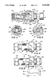
- FIG. 1 is a partial cross-sectional view of a modified valve and coupling device
- FIG. 2 is a section on lines 2--2 of FIG. 1;
- FIG. 3 is a section on lines 3--3 of FIG. 1;
- FIG. 4 is a perspective view of the modified valve and coupling device with a lock hasp in place in the off position
- FIG. 5 is a perspective view of the modified valve and coupling device with a lock hasp in place in the on position
- FIG. 6 is a side plan view of an alternate form of the invention with a clamping fitting positioned thereof;
- FIG. 7 is a cross-section on lines 7--7 of FIG. 6;
- FIG. 8 is a side plan view of the alternate form of the invention shown in FIG. 6 in open position;
- FIG. 9 is an enlarged side plan view of the alternate form shown in FIGS. 6 and 8;
- FIG. 10 is a side plan view of a second alternate form of the invention.
- FIG. 11 is an end plan view on lines 11--11 of FIG. 10.
- An improvement in a valve and coupling assembly 10 having a main tubular valve body 11 the oppositely disposed ends of which are open at 12 and 13 respectively with apertured fittings 12A and 12B positioned thereon.
- a central partition 14 is positioned between said openings at 12 and 13 and defines an inlet chamber 15 and an outlet chamber 16.
- a plurality of annularly aligned and spaced apertures 17 and 17A are formed respectively within each of said inlet and outlet chambers 15 and 16 adjacent the partition 14 respectively as best seen in FIG. 1 of the drawings.
- a valving sleeve 18 is slideably positioned on said tubular valve body member 11 and has a pair of spaced internally formed grooves 19 and 20 each of which have O-ring seals 19A and 20A positioned therein. It will be evident to those skilled in the PG,5 art that by moving the valve sleeve 18 on the tubular valve body 11 as indicated by the arrows in FIGS. 4 and 5 of the drawings that the respective inlet and outlet chambers will be interconnected between the O-ring seals 19A and 20A and thus the valve will be open. The position of the valve sleeve 18 shown in FIG. 1 would indicate a closed condition of the valve venting to atmosphere via the aperture 17 located in the valve chamber 16.
- a lockout fitting 21 can be seen having a generally annular body member 22 centrally apertured at 23.
- the lockout fitting 21 has a pair of semi-annular flanges 24 extending therefrom, portions of which are cut-a-way forming oppositely disposed tapered contoured slots 25 and 26 having apertures within at 25A and 26A respectively.
- a positioning recess area 27 is formed within the annular body member 22 inwardly of said annular flange 24 for registration with a boss 27A on the tubular valve body member 11, best seen in FIGS. 1 and 3 of the drawings.
- the valving sleeve 18 has a pair of oppositely disposed control lugs 28 adjacent one end thereof facing said lockout fitting 21. Each of said control lugs 28 are registrably positioned within the respective slots 25 and 26 as seen in FIGS. 3-4 of the drawings with the valve sleeve 18 in the closed position.
- valve sleeve 18 Upon rotation of said valve sleeve 18 the control lugs 28 move out of their respective slots 25 and 26 allowing the valve sleeve 18 to be moved on the tubular valve body 11 away therefrom to an open position as shown in FIG. 5 of the drawings.
- FIGS. 4 and 5 of the drawings a portion of a lockout hasp 29 can be seen in broken lines having a hasp bar 30 that is pivotally secured within a multiple part support body member 31.
- the hasp bar 30 extends through the apertures at 26A in the annular body member 22 preventing access to the respective slots 25 and 26 by the control lug 28. In this example, the valve is effectively locked in open position.
- the hasp support body 31 encloses the free end of the hasp bar 30 within and prevents same from being manipulated for removal from the body member 22 when the hasp body 31 is secured in locking position.
- the hasp support body 31 is of a two-part configuration hinged at 32 with the hasp bar 31 extending as a hinge pin therethrough. When closed it can be locked as noted above by insertion of a typical pad lock (not shown) through a locking opening 31A as best seen in FIG. 5 of the drawings.
- valve and clamping assembly 33 having the hereinbefore described inlet and outlet chambers 15 and 16 and apertured openings therein at 17 and 17A.
- the same valve element configuration is used with the addition of a two-part clamping cage 34 which is pivotally secured to an enlarged portion 35 of the valve 33 configured for a quick disconnect fitting 36 which registers with a female portion 37 of the fitting which has an engagement lip 37A into which the clamping cage 36 can be engaged and held as seen in FIGS. 8 and 9 of the drawings.
- a valve sleeve 38 having longitudinally and annularly extending lugs 39 is modified by a pair of oppositely disposed locking grooves 40 formed adjacent said respective lugs 39.
- the hasp bar 30 of the lockout hasp 29 can be inserted through the valve body by alignment of the respective grooves 39 with the apertures 17 when in closed position.
- FIGS. 10 and 11 of the drawings a third alternate form of the invention can be seen wherein a valve 41 is shown with the same basic configuration as the valve clamping assembly 11 hereinbefore described having a tubular valve body member 42 with a sliding valve sleeve 43.
- the sleeve 43 has a pair of oppositely disposed contoured control recesses 44 therein. Each of said recesses 44 is positioned inwardly of the sleeve 43 and has an area of reduced diameter at 45.
- a locking handle assembly 46 is secured to the body member 42 with an apertured handle support arm 47 extending therefrom.
- a bifurcated handle assembly 48 is pivotally secured to said handle support arm 47 having spaced control levers 49 extending therefrom.
- An apertured locking arm 50 extends from said handle 48 at right angles to said control levers 49 and can be aligned with said apertured support arm 47 dependent on the relative position of the bifurcated handle 48 as seen in FIG. 10 of the drawings.
- Each of said control levers 49 register within said respective recessed areas 45 in said sleeve 43 so as to engage same and upon activation move the sleeve 43 from an i.e. closed to an open position as seen in broken lines in FIG. 10 of the drawings.
Landscapes
- Engineering & Computer Science (AREA)
- General Engineering & Computer Science (AREA)
- Mechanical Engineering (AREA)
- Quick-Acting Or Multi-Walled Pipe Joints (AREA)
Abstract
An improvement in a valve and coupling device for pressure lines utilized in transferring air or water under pressure to provide a safety lockout feature in which the valve control sleeve can be held in open or closed position in a positive manner by an ancillary lock. The improvement comprises a modified control sleeve and clamping jaw dependent on the valve coupling configuration used in relation to the connection requrirement.
Description
1. Technical Field
This improvement relates to valve and coupling devices used in pressure transfer lines for air or water that utilize a sliding control sleeve that vents to atmosphere in the off or open position.
2. Description of Prior Art
Prior art devices of this type have no specific safety lock-out feature and are directed to on and off positioning of the sliding control sleeve, see U.S. Pat. No. 1,850,879.
In U.S. Pat. No. 1,850,879 a valve and coupling assembly can be seen having a main tubular valve body with an inlet and an outlet port spaced by a partition therebetween. A plurality of aligned apertures extend annularly around the valve body adjacent either side of said partition. A control sleeve has a central, internal groove with oppositely disposed sealing rings attached thereto.
An improvement in a valve coupling assembly to provide positive lock open and lock close positioning of the valve. The valve and coupling assembly is modified to accept a locking device by improvements to the control sleeve and clamping jaws found on various forms of the valve and coupling assemblies.
FIG. 1 is a partial cross-sectional view of a modified valve and coupling device;
FIG. 2 is a section on lines 2--2 of FIG. 1;
FIG. 3 is a section on lines 3--3 of FIG. 1;
FIG. 4 is a perspective view of the modified valve and coupling device with a lock hasp in place in the off position;
FIG. 5 is a perspective view of the modified valve and coupling device with a lock hasp in place in the on position;
FIG. 6 is a side plan view of an alternate form of the invention with a clamping fitting positioned thereof;
FIG. 7 is a cross-section on lines 7--7 of FIG. 6;
FIG. 8 is a side plan view of the alternate form of the invention shown in FIG. 6 in open position;
FIG. 9 is an enlarged side plan view of the alternate form shown in FIGS. 6 and 8;
FIG. 10 is a side plan view of a second alternate form of the invention; and
FIG. 11 is an end plan view on lines 11--11 of FIG. 10.
An improvement in a valve and coupling assembly 10 having a main tubular valve body 11 the oppositely disposed ends of which are open at 12 and 13 respectively with apertured fittings 12A and 12B positioned thereon. A central partition 14 is positioned between said openings at 12 and 13 and defines an inlet chamber 15 and an outlet chamber 16. A plurality of annularly aligned and spaced apertures 17 and 17A are formed respectively within each of said inlet and outlet chambers 15 and 16 adjacent the partition 14 respectively as best seen in FIG. 1 of the drawings.
A valving sleeve 18 is slideably positioned on said tubular valve body member 11 and has a pair of spaced internally formed grooves 19 and 20 each of which have O- ring seals 19A and 20A positioned therein. It will be evident to those skilled in the PG,5 art that by moving the valve sleeve 18 on the tubular valve body 11 as indicated by the arrows in FIGS. 4 and 5 of the drawings that the respective inlet and outlet chambers will be interconnected between the O- ring seals 19A and 20A and thus the valve will be open. The position of the valve sleeve 18 shown in FIG. 1 would indicate a closed condition of the valve venting to atmosphere via the aperture 17 located in the valve chamber 16.
Referring now to FIGS. 1-5 a lockout fitting 21 can be seen having a generally annular body member 22 centrally apertured at 23. The lockout fitting 21 has a pair of semi-annular flanges 24 extending therefrom, portions of which are cut-a-way forming oppositely disposed tapered contoured slots 25 and 26 having apertures within at 25A and 26A respectively.
A positioning recess area 27 is formed within the annular body member 22 inwardly of said annular flange 24 for registration with a boss 27A on the tubular valve body member 11, best seen in FIGS. 1 and 3 of the drawings. The valving sleeve 18 has a pair of oppositely disposed control lugs 28 adjacent one end thereof facing said lockout fitting 21. Each of said control lugs 28 are registrably positioned within the respective slots 25 and 26 as seen in FIGS. 3-4 of the drawings with the valve sleeve 18 in the closed position.
Upon rotation of said valve sleeve 18 the control lugs 28 move out of their respective slots 25 and 26 allowing the valve sleeve 18 to be moved on the tubular valve body 11 away therefrom to an open position as shown in FIG. 5 of the drawings.
Referring now to FIGS. 4 and 5 of the drawings a portion of a lockout hasp 29 can be seen in broken lines having a hasp bar 30 that is pivotally secured within a multiple part support body member 31. The hasp bar 30 extends through the apertures at 26A in the annular body member 22 preventing access to the respective slots 25 and 26 by the control lug 28. In this example, the valve is effectively locked in open position.
In FIG. 4 of the drawings the insertion of the hasp bar 30 effectively locks the valve in closed position. The hasp support body 31 encloses the free end of the hasp bar 30 within and prevents same from being manipulated for removal from the body member 22 when the hasp body 31 is secured in locking position. The hasp support body 31 is of a two-part configuration hinged at 32 with the hasp bar 31 extending as a hinge pin therethrough. When closed it can be locked as noted above by insertion of a typical pad lock (not shown) through a locking opening 31A as best seen in FIG. 5 of the drawings.
Referring now to FIGS. 6-9 of the drawings, an alternate form of the improved improvement can be seen for use on a different form of the valve and clamping assembly 33 having the hereinbefore described inlet and outlet chambers 15 and 16 and apertured openings therein at 17 and 17A. In this example, the same valve element configuration is used with the addition of a two-part clamping cage 34 which is pivotally secured to an enlarged portion 35 of the valve 33 configured for a quick disconnect fitting 36 which registers with a female portion 37 of the fitting which has an engagement lip 37A into which the clamping cage 36 can be engaged and held as seen in FIGS. 8 and 9 of the drawings. A valve sleeve 38 having longitudinally and annularly extending lugs 39 is modified by a pair of oppositely disposed locking grooves 40 formed adjacent said respective lugs 39.
In operation, the hasp bar 30 of the lockout hasp 29 can be inserted through the valve body by alignment of the respective grooves 39 with the apertures 17 when in closed position.
Referring now to FIGS. 10 and 11 of the drawings a third alternate form of the invention can be seen wherein a valve 41 is shown with the same basic configuration as the valve clamping assembly 11 hereinbefore described having a tubular valve body member 42 with a sliding valve sleeve 43. The sleeve 43 has a pair of oppositely disposed contoured control recesses 44 therein. Each of said recesses 44 is positioned inwardly of the sleeve 43 and has an area of reduced diameter at 45. A locking handle assembly 46 is secured to the body member 42 with an apertured handle support arm 47 extending therefrom. A bifurcated handle assembly 48 is pivotally secured to said handle support arm 47 having spaced control levers 49 extending therefrom. An apertured locking arm 50 extends from said handle 48 at right angles to said control levers 49 and can be aligned with said apertured support arm 47 dependent on the relative position of the bifurcated handle 48 as seen in FIG. 10 of the drawings.
Each of said control levers 49 register within said respective recessed areas 45 in said sleeve 43 so as to engage same and upon activation move the sleeve 43 from an i.e. closed to an open position as seen in broken lines in FIG. 10 of the drawings.
Claims (4)
1. An improvement in a valve and coupling assembly comprising a tubular valve body, a pair of spaced longitudinally aligned chambers within said valve body, a plurality of annularly spaced apertures in each of said chambers, a valve sleeve registerable on said valve body, control lugs extending from said valve sleeve and sealing means from said valve sleeves selectively defining a passage between said chambers, the improvement comprises a lockout fitting on said valve body, oppositely disposed slots within said lockout fitting for removable registration of said control lugs therein, oppositely disposed apertures within said lockout fitting adjacent said slots, said control lugs movably positioned from a first open position adjacent said slots to a second closed position within said slots, a locking bar engagable through one of said apertures in said lockout fitting restricting access to said slots.
2. An improvement in a valve and coupling assembly comprising a tubular valve body, a pair of spaced longitudinally aligned chambers within said valve body, a plurality of annularly spaced apertures in each of said chambers, a valve sleeve registerable on said valve body and control lugs extending from said valve sleeve and sealing means within said valve sleeve selectively defining a passageway between said chambers,
said improvement comprises a two-part clamping cage on said tubular valve body, said clamping cage having oppositely disposed slots registerable with said control lugs, said valving sleeve having a pair of oppositely disposed transversely aligned locking grooves adjacent said lugs, a hasp bar extending through oppositely disposed aligned annularly spaced apertures in one of said valve chambers and through said locking grooves restricting longitudinal movement of said valve sleeve on said valve body.
3. The improvement in a valve and coupling assembly comprising a tubular valve body, a pair of spaced longitudinally aligned chambers within said valve body, a plurality of aligned circumferentially spaced apertures in each of said chambers, a valving sleeve movably positioned on said valve body, sealing means within said valve sleeve selectively defining a passage between said chambers,
the improvement comprising a pair of oppositely disposed controlled recesses in said sleeve, a lockout handle assembly on said tubular valve body, said lockout handle assembly comprising a fixed multiple apertured support arm, a bifurcated handle pivotally secured to said support arm, control arms and an apertured locking arm extending from said handle, said control arms registerable with said respective control recesses in said sleeve, means for aligning said apertured locking arm and support arm in relation to one another.
4. The improvement in a valve and coupling assembly of claim 3 wherein said means for aligning said apertured locking arm and said support arm in relation to one another comprises repositioning said bifurcated handle and said valving sleeve interconnected thereto.
Priority Applications (1)
| Application Number | Priority Date | Filing Date | Title |
|---|---|---|---|
| US07/745,253 US5161568A (en) | 1991-08-14 | 1991-08-14 | Safety lockout valve and coupling |
Applications Claiming Priority (1)
| Application Number | Priority Date | Filing Date | Title |
|---|---|---|---|
| US07/745,253 US5161568A (en) | 1991-08-14 | 1991-08-14 | Safety lockout valve and coupling |
Publications (1)
| Publication Number | Publication Date |
|---|---|
| US5161568A true US5161568A (en) | 1992-11-10 |
Family
ID=24995901
Family Applications (1)
| Application Number | Title | Priority Date | Filing Date |
|---|---|---|---|
| US07/745,253 Expired - Fee Related US5161568A (en) | 1991-08-14 | 1991-08-14 | Safety lockout valve and coupling |
Country Status (1)
| Country | Link |
|---|---|
| US (1) | US5161568A (en) |
Cited By (10)
| Publication number | Priority date | Publication date | Assignee | Title |
|---|---|---|---|---|
| US5462316A (en) * | 1994-05-19 | 1995-10-31 | Campbell Fittings, Inc. | Quick action fluid coupling |
| US5638857A (en) * | 1995-09-05 | 1997-06-17 | Alcumbrack; Douglas C. | Air lockout device |
| FR2750753A1 (en) * | 1996-07-04 | 1998-01-09 | Sevylor International | Blocking valve controlling the flow of fluids |
| US5823023A (en) * | 1997-10-29 | 1998-10-20 | Brady Usa, Inc. | Locking device for a valve |
| US20050046178A1 (en) * | 2003-08-27 | 2005-03-03 | Smc Kabushiki Kaisha | Tube joint |
| US20070006922A1 (en) * | 2005-07-07 | 2007-01-11 | Nesbitt Harry C | Pneumatic valve with lockout |
| US20160047505A1 (en) * | 2011-03-21 | 2016-02-18 | Engineered Controls International, Llc | Rapid-connect coupler with vent-stop |
| US9732893B2 (en) | 2010-08-10 | 2017-08-15 | Engineered Controls International, Llc | Rapid-connect coupler |
| US9897239B2 (en) | 2015-04-27 | 2018-02-20 | Engineered Controls International, Llc | Rapid-connect coupler with vent stop |
| US10386017B2 (en) | 2015-12-03 | 2019-08-20 | Engineered Controls International, Llc | Low emission nozzles and receptacles |
Citations (7)
| Publication number | Priority date | Publication date | Assignee | Title |
|---|---|---|---|---|
| GB191006892A (en) * | 1910-03-18 | 1911-03-16 | John Russell Sharp | Improvements in Taps or Valves. |
| US1850879A (en) * | 1930-04-25 | 1932-03-22 | Nathan C Hunt | Valve and coupling |
| US2509671A (en) * | 1946-02-01 | 1950-05-30 | Niels A Christensen | Slide valve |
| US2688340A (en) * | 1949-01-13 | 1954-09-07 | St West Inc | Pressure equalizing valve with pivotally mounted operator |
| US3094306A (en) * | 1958-11-17 | 1963-06-18 | Martin B Conrad | Telescopic valve |
| US3750752A (en) * | 1971-04-30 | 1973-08-07 | Hydril Co | Completion and kill valve |
| US3960366A (en) * | 1971-11-01 | 1976-06-01 | Dresser Industries, Inc. | Reverse acting lock open crossover valve |
-
1991
- 1991-08-14 US US07/745,253 patent/US5161568A/en not_active Expired - Fee Related
Patent Citations (7)
| Publication number | Priority date | Publication date | Assignee | Title |
|---|---|---|---|---|
| GB191006892A (en) * | 1910-03-18 | 1911-03-16 | John Russell Sharp | Improvements in Taps or Valves. |
| US1850879A (en) * | 1930-04-25 | 1932-03-22 | Nathan C Hunt | Valve and coupling |
| US2509671A (en) * | 1946-02-01 | 1950-05-30 | Niels A Christensen | Slide valve |
| US2688340A (en) * | 1949-01-13 | 1954-09-07 | St West Inc | Pressure equalizing valve with pivotally mounted operator |
| US3094306A (en) * | 1958-11-17 | 1963-06-18 | Martin B Conrad | Telescopic valve |
| US3750752A (en) * | 1971-04-30 | 1973-08-07 | Hydril Co | Completion and kill valve |
| US3960366A (en) * | 1971-11-01 | 1976-06-01 | Dresser Industries, Inc. | Reverse acting lock open crossover valve |
Cited By (20)
| Publication number | Priority date | Publication date | Assignee | Title |
|---|---|---|---|---|
| US5462316A (en) * | 1994-05-19 | 1995-10-31 | Campbell Fittings, Inc. | Quick action fluid coupling |
| US5638857A (en) * | 1995-09-05 | 1997-06-17 | Alcumbrack; Douglas C. | Air lockout device |
| FR2750753A1 (en) * | 1996-07-04 | 1998-01-09 | Sevylor International | Blocking valve controlling the flow of fluids |
| US5823023A (en) * | 1997-10-29 | 1998-10-20 | Brady Usa, Inc. | Locking device for a valve |
| US20050046178A1 (en) * | 2003-08-27 | 2005-03-03 | Smc Kabushiki Kaisha | Tube joint |
| US7213845B2 (en) * | 2003-08-27 | 2007-05-08 | Smc Kabushiki Kaisha | Tube joint |
| US20070006922A1 (en) * | 2005-07-07 | 2007-01-11 | Nesbitt Harry C | Pneumatic valve with lockout |
| US7509972B2 (en) * | 2005-07-07 | 2009-03-31 | Parker-Hannifin Corporation | Pneumatic valve with lockout |
| US20090184272A1 (en) * | 2005-07-07 | 2009-07-23 | Harry Clayton Nesbitt | Normally closed pneumatic diaphragm valve with mechanical override with lockout |
| US9732893B2 (en) | 2010-08-10 | 2017-08-15 | Engineered Controls International, Llc | Rapid-connect coupler |
| US10281073B2 (en) | 2010-08-10 | 2019-05-07 | Engineered Controls International, Llc | Rapid-connect coupler |
| US20160047505A1 (en) * | 2011-03-21 | 2016-02-18 | Engineered Controls International, Llc | Rapid-connect coupler with vent-stop |
| US9857010B2 (en) * | 2011-03-21 | 2018-01-02 | Engineered Controls International, Llc | Rapid-connect coupler with vent-stop |
| US10718456B2 (en) | 2011-03-21 | 2020-07-21 | Engineered Controls International, Llc | Rapid-connect coupler with vent-stop |
| US9897239B2 (en) | 2015-04-27 | 2018-02-20 | Engineered Controls International, Llc | Rapid-connect coupler with vent stop |
| US10208877B2 (en) | 2015-04-27 | 2019-02-19 | Engineered Controls International, Llc | Rapid-connect coupler with vent stop |
| US10386017B2 (en) | 2015-12-03 | 2019-08-20 | Engineered Controls International, Llc | Low emission nozzles and receptacles |
| US10883665B2 (en) | 2015-12-03 | 2021-01-05 | Engineered Controls International, Llc | Low emission nozzles and receptacles |
| US11162641B2 (en) | 2015-12-03 | 2021-11-02 | Engineered Controls International | Low emission nozzles and receptacles |
| US11796135B2 (en) | 2015-12-03 | 2023-10-24 | Engineered Controls International, Llc | Low emission receptacles |
Similar Documents
| Publication | Publication Date | Title |
|---|---|---|
| US5161568A (en) | Safety lockout valve and coupling | |
| US3538940A (en) | Fitting assembly | |
| US5387017A (en) | Coupling for attachment to the end of a pipe for securement to the pipe or for joining pipes together | |
| EP0694315B1 (en) | Stopcock | |
| US4173328A (en) | In-line shut-off valve | |
| US4711268A (en) | Valve manifold | |
| US4275842A (en) | Decoking nozzle assembly | |
| US1850879A (en) | Valve and coupling | |
| US3236251A (en) | Valve unit | |
| US4399977A (en) | Ball valve | |
| US7509972B2 (en) | Pneumatic valve with lockout | |
| US4776614A (en) | Coupling with lock indicator | |
| CA1266038A (en) | Ball valve with seat loading mechanism | |
| KR20010040086A (en) | Fluid-directional control device for solenoid valve assembly | |
| US3404705A (en) | Coupling and valve mechanism | |
| CN102203486A (en) | System and method for restricting access to a valve | |
| CA3019480C (en) | Manifolds for pressure relief systems | |
| GB1185195A (en) | Improvements relating to valved coupling devices for use in fluid systems | |
| US5232199A (en) | Sliding gate line blind | |
| US4901763A (en) | Fluid valve apparatus | |
| JPH04248078A (en) | Multifunctional multiport slide valve | |
| JPS61189391A (en) | Female coupler in fluid circuit | |
| CA1051747A (en) | Multiple port fluid control device | |
| EP1062443B1 (en) | Sliding plate valve | |
| US5168897A (en) | Quick and dry coupling |
Legal Events
| Date | Code | Title | Description |
|---|---|---|---|
| AS | Assignment |
Owner name: KEEN MANUFACTURING INC.,, OHIO Free format text: ASSIGNMENT OF ASSIGNORS INTEREST.;ASSIGNOR:TURVEY, TERRY K.;REEL/FRAME:005833/0646 Effective date: 19910910 |
|
| REMI | Maintenance fee reminder mailed | ||
| LAPS | Lapse for failure to pay maintenance fees | ||
| FP | Lapsed due to failure to pay maintenance fee |
Effective date: 19961113 |
|
| STCH | Information on status: patent discontinuation |
Free format text: PATENT EXPIRED DUE TO NONPAYMENT OF MAINTENANCE FEES UNDER 37 CFR 1.362 |